1
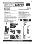
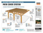
BUILDERS
Wood Truss Restraint and Bracing Guide
Using Simpson Strong‑Tie ® Products To Meet the Recommendations of the Building Component Safet y Information (BCSI) Guide
( 800 ) 999-5099 | www.strongtie.com
Wood Truss Restraint and Bracing Guide
Touch It Once – You’re Done
Positioning and bracing trusses during installation can be a time-consuming process that can drive up labor costs on the
project. After all the bracing is measured, cut and installed, it will ultimately be pulled off before the roof sheathing goes on.
Not only does this tedious installation and removal create additional labor expenses, it also costs money to collect and dispose
of the wood bracing material left on the jobsite. More importantly, there are safety concerns when sheathing crews are forced
to work on top of non-braced trusses.
With Simpson Strong-Tie® restraint and bracing products, installing bracing is faster and easier, and since they stay on the
trusses permanently, installers touch them once and walk away. No need to come back to remove them, no wasted lumber –
removal and disposal costs are eliminated. In addition, since they stay in place, sheathing crews are able to work on braced
trusses that are more stable. With Simpson Strong-Tie restraint and bracing products, crews work faster and safer.
TSBR: Efficiency in Spacing and Restraint
W
19/16
"
L
1 /1
TSBR2-24
9 6
U.S. Patent
6,993,882
(TSBR2-16 similar)
"
D
TSBR Truss Spacer Restraint – The Most
Efficient Way to Satisfy BCSI Recommendations
• TSBR captures the trusses at exact on-center spacing
without measuring or cutting
• Easily “grabs” onto the truss – can be put in place with
one hand
• Minimum nailing option for even faster installation
• Installs without prongs or sharp edges, which are potential
safety hazards
• Stays in place during sheathing, saving time and making
the roof more stable for workers
• Boxed tubular shape for safety and strength in tension and
compression
TSBR
lateral spacer restraint
TBD22
diagonal brace
Dimensions (in.)
L
W
D
Fasteners
(Total)
TSBR2-162 (Min.)
17 1⁄2
1 1⁄4
1 1⁄4
TSBR2-16 (Max.)
17 1⁄2
1 1⁄4
1 1⁄4
TSBR2-242 (Min.)
25 1⁄2
1 3⁄4
1
(2) 10d
TSBR2-24 (Max.)
25 ⁄2
1 3⁄4
1
(4) 10dx1 1⁄2"
Model No.
1
Allowable Loads (lbs.)
DF/SP
SPF/HF
Compression
Tension
Compression
(2) 10d
540
180
465
Tension
155
(4) 10dx1 1⁄2"
540
455
465
390
500
180
430
155
500
455
430
390
1. No load duration increase allowed.
2. Minimum nailing meets or exceeds the temporary lateral restraint recommendations of WTCA/TPI BCSI-08.
3. Nails: 10dx1 1⁄2 = 0.148" dia. x 1 1⁄2" long, 10d = 0.148" dia. x 3" long.
©2011 Simpson Strong-Tie Company Inc. F-TSBRTBD2211 3/11 exp. 12/31/14
Wood Truss Restraint and Bracing Guide
How to Satisfy BCSI Temporary Restraint and
Industry-standard guidelines for the safe erection and installation of wood trusses
are published in the Building Component Safety Information: Guide to Good Practice for
Handling, Installing, Restraining & Bracing of Metal Plate Connected Wood Trusses
(BCSI). The BCSI guide is published jointly by the Structural Building Components
Association (SBCA), its Wood Truss Council and the Truss Plate Institute (TPI).
This document is intended to show the proper application of Simpson Strong‑Tie
lateral restraint (TSBR) and diagonal bracing (TBD22) products when used in
conjunction with the BCSI recommendations for restraining and bracing the
top chord, bottom chord and web planes of the trusses. It is not intended to
replace the BCSI or its Summary Sheets. See BCSI B1 and B2 for ground bracing
recommendations.
Top-Chord Temporary Lateral Restraint and Bracing
with Simpson Strong-Tie TSBR and TBD22
Image courtesy of SBCA
Excerpts from BCSI – 08
Lateral stability of truss systems is typically
comprised of two components:
• Continuous Lateral Restraint
• Diagonal Bracing
Lateral Restraint: also known as Continuous Lateral
Brace (Restraint): A line of structural members
installed at right angles to a chord or web member of
a truss to reduce the laterally unsupported length of
the truss member.
For top-chord temporary lateral restraint, TSBR must be installed at each pitch
break (change in chord direction) and may not exceed the on-center spacing
shown in the table below (from BCSI). Only one row of TSBRs is required at the
peak of the trusses; there is no need to install TSBRs on both sides. Additionally,
if the height of the truss over the exterior supporting structure is more than 10",
install an additional row of TSBRs at this location.
Maximum Spacing of TSBR Spacer Restraints on Top Chord (per BCSI Table B2-1)
Overall Truss Length 1
Up to 30'
30'– 45'
45'–60'
60'–80' 2
1. The Overall Truss Length refers to the overall length of the truss including cantilevers, exclusive of overhangs.
2. BCSI recommends consulting with a Registered Design Professional for erection restraint and bracing
assistance for truss lengths greater than 60'. (IBC [2009] Section 2303.4.1.3 requires the Registered
Design Professional to do the design for the temporary installation restraint and bracing and the
permanent individual truss member restraint and bracing for trusses with clear spans of 60' or greater.)
* = *Pitch break
p
Diagonal Bracing: A structural member installed
at an angle (approx. 45o) to a truss chord or
web member and intended to temporarily and/or
permanently stabilize truss members and/or trusses.
5'-6"
*
d a row
TS
Under 8'
*
The continuous lateral restraint forces the connected
truss members to move in the same direction.
Maximum Spacing
10' on-center
8' on-center
6' on-center
4' on-center
Over 8' (add a row of TSBR)
*
5'-6"
*
5'-6"
8'-10"
3'-4"
*
4'-4"
33'-0" Span
Example of TSBR placement on top chord
of truss with multiple pitch breaks.
TSBR captures
exact O.C.
spacing
TSBR spacer restraint
10" or greater
over wall height
Truss attachment
required at support(s)
Diagonal Bracing provides stability by resisting the
domino effect of connected trusses.
See BCSI B1 and B2 for
ground bracing recommendations
Wood blocking
at odd spacings
tTSBR for top chord lateral restraint
©2011 Simpson Strong-Tie Company Inc. F-TSBRTBD2211 3/11 exp. 12/31/14
Bracing Recommendations
Use TBD22 for diagonal bracing. TBD22 must be installed immediately after the first
five trusses are erected, and then after every 10 trusses are set as well as at the end
of the truss run.
7
6
5
4
3
AHEP
(See back page)
TSBR spacing between rows
is based on overall truss length
60'
TSBR
Edge Nail
4'
T20
T19
T20
1
TSBR
T2
Face Nail
TBD22
T19
Typical TBD22 Top Chord
Installation with Minimum Nailing
T27
T26
T25
T18
T29
T28
T37
T22
T41
46'
TBD22 for top-chord diagonal bracing
Diagonally brace bottom chord and web planes at
the same locations as top chord diagonal bracing
T42
T43
T44
Bottom Chord Lateral Restraint and Bracing
with the TSBR and TBD22
W
T17
T16
T15
T24
T2
1
T19
1
T19
T19
32'
TSBRs
W
Wood blocking
AHEPs (see back page)
Truss top chords and
webs not shown for clarity
Runs of TBD22
©2011 Simpson Strong-Tie Company Inc. F-TSBRTBD2211 3/11 exp. 12/31/14
T20
T20
T22
T19
T20
T20
TBD22 diagonal bracing must be installed on the bottom chords at the same
intervals as the top chord diagonal bracing.
T31
W
T2
Use TSBR for both temporary and permanent bottom chord lateral restraint.
Bottom chords must be laterally restrained during installation at 15' o.c. or less
until the ceiling is installed. If there is no ceiling directly attached to the bottom
chords, install rows of TSBR during truss placement at the on-center spacing
specified on the Truss Design Drawing (TDD) or by the building Designer
(10' o.c. max). This will simultaneously satisfy both temporary and permanent
restraint requirements.
T45
Adding Lateral Restraints and Diagonal Bracing to the Truss Placement Diagram
Once the on-center spacing of the lateral restraints is determined from BCSI Table B2-1, locating the runs of TSBRs on the Truss Placement
Diagram (TPD), typically provided by the component manufacturer, is easy for each of the different truss types, as shown below. Once the TSBRs
have been located, the locations of the required diagonal bracing (TBD22) can easily be added, starting with the first five trusses in the run and
then every ten (10) truss spaces thereafter. Each truss run terminates with a set of diagonal braces as indicated below. Having the restraint and
bracing locations clearly delineated will assist in getting all members of the erection crew familiar with the intended erection plan.
28'
1¼" ened
t
Flat
W
T8
W
W
TBD22
Typical
W
"
1/
L
9 16
D
T6
3¹⁄₂"
VTCR
(See back page)
W
W
0
11
9
7
ON ®
PS e
S Mong-T
St
50'
T7
T35
T33
9 6
46'
T39
T34
T32
1 /1
Typical
T38
T40
T30
TSBR2-24
5
3
12
10
8
6
4
2
1
2"
"
2¹⁄₂
GBC
W
(See back page)
4'
16'
12'
28'
88'
Typical Truss Placement Diagram Showing Locations for Truss Installation/Erection Lateral Restraints and Diagonal Bracing
The TPD often identifies other products such as truss-to-plate tiedowns, truss-to-truss connectors, etc. While these have been left off the
TPD above for the purpose of clarity, the following other products are included on the TPD above: the VTCRs (for connecting the valley trusses),
AHEPs (adjustable hip-end purlins for step down hip systems), and GBCs (gable end brace connectors). Please see the back page of this flier for
information about these products.
NOTICE: Proper truss erection, installation, restraint and bracing requires an understanding of triangulation within, and between, the various planes of the truss
(i.e., top chord, bottom chord and web). It is critical to note that all rows of Simpson Strong-Tie® TSBR, installed for lateral restraint, must be diagonally braced with
TBD22 bracing installed in an ‘X’ pattern. TSBR spacer restraints alone are not adequate to resist the buckling and overturning forces in the members to which they
are attached without the rigidity provided by the TBD22 diagonal bracing spaced as indicated.
©2011 Simpson Strong-Tie Company Inc. F-TSBRTBD2211 3/11 exp. 12/31/14
"
Web Lateral Restraint and Bracing with the TSBR and TBD22
The TSBR spacer restraint is ideal for permanent web member lateral restraint
requirements because it is easier to install than long wood braces which need to
be overlapped over two trusses at each end. Install the TSBR wherever the Truss
Design Drawing indicates continuous lateral web restraint is required. TBD22
diagonal bracing must be installed on the web members along the row of TSBRs
every 20' and at each end of the run of similar trusses.
Note: If no web members require TSBR spacerrestraint, install TBD22 diagonal bracing during
truss installation on the web members in line
with the bottom chord TSBRs and at the
same intervals as the top-chord and
The Truss Design Drawing will indicate required
bottom-chord diagonal bracing.
locations for lateral restraint on web members.
Bracing of Piggybacks
TSBR and TBD22 offer an effective means to permanently laterally restrain and brace
piggyback assemblies consisting of a supporting “base” truss and a supported “cap”
truss that is set directly on top of the base truss. Both the TSBR and TBD22 lie flat in
the top chord plane of the base truss, eliminating the need to raise the bottom chords
of the cap trusses, such as is necessary when purlins and diagonal bracing are used.
The figure below illustrates the use of TSBR and TBD22 to permanently laterally
restrain and brace the flat top chord section of the base trusses prior to the
installation of the cap trusses. In this case, the TSBRs are installed at the top
chord purlin spacing indicated on the Truss Design Drawing, and the TBD22
diagonal bracing is installed at 10' intervals or as otherwise required by the
Designer (reference BCSI-B3).
Supported (“Cap”)
Frames
TSBR
spacer restraint
TBD22 diagonal bracing
Excerpts from BCSI – 08 (Cont.)
Section B2 contains the following statement:
Proper truss erection, installation, restraint and
bracing require an understanding of triangulation
within and between the various planes of the truss
(i.e., top chord, bottom chord and web). It is critical
to note that all lateral restraints must be braced.
Lateral restraint by itself is not adequate to resist the
buckling forces in the members to which it is attached
without the rigidity provided by bracing. Bracing is
typically provided by adding diagonal bracing within
the same plane of the lateral restraint.
Top-Chord Plane Lateral Restraint Spacing
From BCSI table B2-1, the maximum on-center
locations for top chord temporary lateral restraints are
determined by the overall truss length and the length
of the top chord between pitch breaks (i.e., change of
slope). Ground bracing is then placed in line with the
required locations of the rows of lateral restraints.
Web Member Plane Lateral Restraint and
Diagonal Bracing Spacing
The Truss Design Drawing will specify the webs (if
any) requiring permanent lateral restraint and how
many restraints are needed (1 or 2 generally).
The web Diagonal Braces, acting together with the
Top Chord and Bottom Chord Temporary Lateral
Restraints, form triangulation perpendicular to the
plane of the trusses, thus creating additional lateral
stability for the trusses.
Diagonal Bracing installed for the purpose of
increasing the stability of the truss system during
installation shall be installed on web members
(verticals whenever possible), located at or near each
row of Bottom Chord Lateral Restraints. Diagonal
Braces are required at each end of a Truss row and
repeated every 10 Truss spaces (20' maximum).
Bottom-Chord Plane Lateral Restraint Spacing
BCSI recommends the following spacings for lateral
restraint of the bottom chord plane, based upon
whether the restraint will be part of the temporary
bracing or permanent bracing system:
• For temporary bracing systems the lateral restraint
rows must not be over 15' on-center.
• For the permanent bracing system, the lateral
restraint rows should be spaced as specified on
the construction documents or the Truss Design
Drawing, not to exceed 10' on-center.
Base trusses
(bracing not shown for clarity)
Excerpt from IBC 2009
During the installation of the base trusses (and then
the supported cap frames), the top chord, bottom chord and web members must
be temporarily laterally restrained and braced until all of the permanent bracing is
in place. This is accomplished the same as all other trusses – refer to the respective
sections of this document for information regarding top chord, bottom chord and
web lateral restraint and diagonal bracing with the TSBR and TBD22.
©2011 Simpson Strong-Tie Company Inc. F-TSBRTBD2211 3/11 exp. 12/31/14
2303.4.1.3 Trusses spanning 60 feet or greater.
The owner shall contract with any qualified registered
design professional for the design of the temporary
installation restraint/bracing and the permanent
individual truss member restraint/bracing for all
trusses with clear spans [sic] 60 feet (18 288 mm)
or greater.
Wood Truss Restraint and Bracing Guide
TBD22: Save Time – Right Out of The Box
The TBD22 diagonal truss brace offers a time-saving substitute for wood diagonal bracing that helps satisfy the prescriptive
recommendations of WTCA/TPI BCSI when used with the TSBR spacer restraint. When installed on the top and bottom chords,
as well as the web planes, the TBD captures the forces generated by the TSBR and transfers them diagonally to the edge of the
braced-truss system.
For ease of handling, the TBD travels in a box like a flat strap, and is formed into an ‘A’ shape as it is pulled from the carton
to provide rigidity and prevent sagging between trusses during installation. As it is fastened to the trusses the brace flattens,
allowing sheathing to be installed right over it and saving the time typically needed to remove wood bracing. This also creates
a safer work environment since the brace stays in place while sheathing is installed.
1¼" ened
t
Flat
The TBD22 Diagonal Brace:
• Helps satisfy prescriptive temporary bracing
recommendations of the WTCA/TPI BCSI
• Rigid A-shape design virtually eliminates sagging between
trusses spaced 16"–24" on center
TBD22
US Patent Pending
• Saves the time needed to remove diagonal bracing before
sheathing
• Eliminates the dangerous practice of removing bracing prior
to sheathing
• Has a dimpled nailing grid which allows installation with
standard pneumatic fasteners
• 160' of bracing in an easy-to-handle carton
Installation:
• Use all specified fasteners; see the General Notes section of our
Wood Construction Connectors catalog for more information.
• Strap does not have holes for fasteners. Nails shall be
installed in the dimpled areas and placed to maintain a
minimum of 1⁄4" strap edge distance and a minimum of 1⁄2"
center-to-center distance. Nails should be installed in the
center of the lumber narrow face and with a minimum edge
distance of 1" on the lumber wide face.
The TBD22 is formed
into an ‘A’ shape as it is
pulled from the box
TSBR
spacer restraint
TBD22
diagonal bracing
• TBD22 braces span diagonally at approximately 45° in an
X-configuration.
• Strap shall not be slack, but tight and ready to engage
in tension.
• At the end of the TBD22 braces trusses shall be laterally
restrained to resist out of plane forces.
• Bracing locations shown in the drawing are recommendations
for temporary bracing only. Installation of TBD22 braces for
permanent lateral bracing shall be per the Designer.
Allowable Loads for TBD22 Diagonal-Bracing Strap
Fasteners
Model No.
Allowable
Tension Loads 1
Strap Ends
Intermediate
Trusses
DF/SP
SPF/HF
TBD22 (Min.)
Face: (1) 10dx1 ½"
Edge: (1) 10dx1 ½"
(1) 10dx1 ½"
430
390
TBD22 (Max.)
Face: (2) 10dx1 ½"
Edge: (1) 10dx1 ½"
(1) 10dx1 ½"
565
520
1.
2.
3.
4.
Allowable loads have been increased for construction and wind loading with no further increase allowed.
Minimum nailing loads meet or exceed the WTCA/TPI BCSI-08 recommendations.
TBD22 straps must always be installed in an ‘X’ pattern, taut and ready to engage in tension.
Nails: 10dx1 ½" = 0.148 dia. x 1 ½" long.
©2011 Simpson Strong-Tie Company Inc. F-TSBRTBD2211 3/11 exp. 12/31/14
Wood Truss Restraint and Bracing Guide
Additional Truss Placement Solutions
Simpson Strong-Tie manufactures literally thousands of connector products for light frame construction. We offer the largest selection
of lab and field tested connectors, along with the dedicated engineers and field support reps to back them up. You can count on our
products and our people to perform. Below are three innovative products that provide engineered solutions to specific bracing or
connection needs of the truss placement example depicted within this bulletin.
Single-Sided Valley Truss Clip (VTCR)
The VTCR is a single-sided valley truss clip that provides a positive
connection between the valley truss and the supporting framing below.
Installed on top of the roof sheathing, it eliminates the need to add a
support wedge under the valley truss or to bevel the bottom chord to match
the roof pitch. The connector’s front-face installation contributes to its
ease of installation, and it installs with nails or with Simpson Strong-Tie®
Strong-Drive® SD structural-connector screws, the latter resulting in a
nearly 30% increase in uplift capacity.
7
6
5
4
3
Adjustable Hip-End Purlin (AHEP)
for Wood and Cold-Formed Steel
Truss Construction
This innovative, patent-pending product serves
as an installation aid for step-down hip trusses
by accurately spacing and laterally restraining
the flat section of the top chords. Additionally,
the AHEP can remain in place and function as
a structural purlin for the hip-end system. With
its interlocking design that allows for linear
installation, the AHEP can be installed in line
with the end jack trusses to maintain framing
alignment from eave to hip or peak.
Gable End
Truss
Gable Brace Connector (GBC)
The Simpson Strong-Tie GBC is specifically designed for the tension
and compression requirements of the gable brace connection. The GBC
provides improved anchorage of the diagonal brace to the top of the gable
end wall using a minimum 2x4 stress-graded lumber. The GBC is rated for
diagonal brace angles from 40° to 60°.
®
Wall
Top
Plate
2"
min.
Gable
Brace
Gable Brace
Flush at
Inside Edge
of Plates
For more information about these and other Simpson Strong-Tie connector products, please reference our latest
Wood Construction Connectors catalog, or visit our website at www.strongtie.com.
This flier is effective until June 30, 2013, and reflects information available as of March 1, 2011. This information
is updated periodically and should not be relied upon after June 30, 2013; contact Simpson Strong‑Tie for current
information and limited warranty or see www.strongtie.com.
©2011 Simpson Strong-Tie Company Inc. • P.O. Box 10789, Pleasanton, CA 94588
F-TSBRTBD2211 3/11 exp. 12/31/14
800-999-5099
www.strongtie.com