1
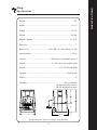
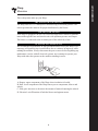
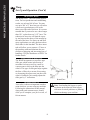
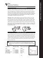
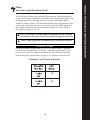
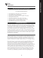
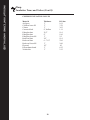
Instruction Manual
3771 Monarch Street • Frederick, CO 80530 • www.inteccorp.com
Local: (303) 833-6644 • Fax: (303) 833-6650 • Toll Free: (800) 666-1611
CONTENTS
Wasp
Table of Contents
Introduction ..................................................................1
Safety First ...................................................................2
Specifications ................................................................3
Overview ......................................................................4
How The System Works ..............................................7
Set-Up and Operation...................................................8
Operational Guidelines...............................................11
Sidewall Notes & Material Specifications.................12
Generators and Extension Cords..............................14
Maintenance ...............................................................15
Troubleshooting .........................................................21
Mechanical Drawings ................................................24
Electrical Drawings.....................................................29
Claims, Damage or Loss ............................................32
Contacting Intec .........................................................36
Insulation Terms and Values .....................................37
Warranty ....................................................................39
Rev 03/10
Thank you for purchasing an Intec insulation system. Since 1977, both
professional contractors and do-it-yourself equipment users have looked to
Intec as the industry leader in the design and manufacture of innovative
portable insulation blowing equipment. We take pride in making your job as
easy and profitable as possible.
The right system for your needs: Intec strives to provide you with the best
combination of portability, functionality, and installation versatility to surpass
your desired success. From lightweight polyethylene units with removable
hoppers, to larger units with increased production rates and installation
versatility, all of our durable systems are made to maximize your profit
generating potential.
Best-in-class Customer Service: Total ease of use extends beyond your initial
purchase of an Intec system to your evolving needs thru the entire lifecycle.
Both before and after the sale service is important to keep you running at
peak operating capabilities. Intec’s technical team provides installation
assistance in addition to maintenance suggestions and trouble-shooting
support. In addition to blowing machines, Intec produces a range of
accessories that will increase your productivity when dense packing, damp
spraying, and installing net and blow.
Thank you for partnering with Intec. We appreciate the confidence and trust
you have placed in us, and wish you many profit-generating opportunities!
Ray Lavallee
President
INTRODUCTION
Intec appreciates your business
When working with insulation, always wear a long sleeve shirt, gloves, a hat, goggles or safety glasses
for eye protection. Use 3M brand #8710 nose/mouth dust mask or a Niosh N95 (or equivalent) for
respiratory protection.
Safety rules:
•
•
•
•
•
•
•
Do not operate the machine without the hopper firmly attached to the base.
Always use the supplied extension cord with this machine at all times.
Never reach into the hopper while operating.
Rotating agitator blades can cause severe injury. Stop all motors and disconnect the
extension cord before attempting to remove any foreign object or jam.
Never operate this equipment if the operator or the machine is in standing water,
snow or rain.
Never point insulation hose in the direction of people or pets.
Do not operate this equipment when minors are present or leave unattended. Always
disconnect power from machine before leaving unattended.
SYMBOLS
The following signal words and meanings are intended to explain the levels of risk associated with the use
of product.
SYMBOL
SIGNAL
MEANING
DANGER: Indicates an immediate hazardous situation which, if not avoided, could result in
death or serious injury.
WARNING: Indicates a potentially hazardous situation which, if not avoided, could result in
death or serious injury.
CAUTION: Indicates a potentially hazardous situation which, if not avoided, may result in
minor or moderate injury.
SERVICE:
Servicing requires extreme care and knowledge and
should be performed only by a qualified service
technician. For service we suggest you return the
product to the nearest AUTHORIZED SERVICE
CENTER for repair. When servicing, use only
original equipment replacement parts.
WARNING:
To avoid personal injury, do not attempt to operate this
equipment until you thoroughly read and completely
understand the operator’s manual. Save this operator’s
manual and review for continuing safe operation and
instructing others who may operate this equipment.
WARNING:
Observe all normal safety precautions related to avoid
electrical shock.
WARNING:
The operation of any products can result in foreign objects being thrown into your eyes, which can
result in severe eye damage. Before beginning operation, always wear safety goggles or safety glasses
with side shields and a full face shield when needed. We recommend Wide Vision Safety Mask for use
over eyeglasses or standard safety glasses with side shields. Always wear eye protection which is
marked to comply with ANSI Z87.1.
2
SAFETY FIRST
Wasp
Safety First
Height .......................................................................................................44''
Width ..................................................................................................31-1/2"
Length .................................................................................................32-3/4"
Weight ............................................................................................... 280 lbs.
Hopper Capacity .............................................................................. 11 cu. ft.
Hose Size ................................................................................................... 3"
Blowers (2)...........................................101 CFM x 2 = 202 CFM @ 3.2 PSI
Agitator Motor ..................................................................................1-1/2 hp
Gearbox ....................................................Worm drive, permanently greased
Airlock ..................................................... 8" x 10", steel, cast urethane seals
Electric .......................................................................(2)-115V/20 amp 60Hz
Agitator ......................................................................................Vertical style
Wheels .........................................................................................................8"
Warranty ............................................................................. One year limited;
90 days limited on electric,
blower and airlock system.
31-1/2”
32-3/4”
Specifications are subject to change without notice.
3
Specifications
Wasp
Specifications
Three subsystems make up your Wasp:
THE AGITATOR AND AIRLOCK
The Wasp runs on a 1-1⁄2 horsepower motor driving an enclosed gearbox. The
airlock positions the material for proper distribution by the blower.
THE BLOWER MOTOR
Your Wasp is equipped with two 101 CFM two-stage blower motors to push the
material through the hose and into the attic with optimum pressure and output.
The blower is connected to the air intake port of the airlock by a hose.
ELECTRICAL COMPONENTS
We recommend two dedicated 20 amp grounded outlets to run your Wasp. Less
amperage will possibly trip circuit breakers due to variances in amperage while
running the machine. Always disconnect the power source before beginning any
maintenance. And as with all electrical systems, never attempt to operate your
Wasp with either the operator or the machine standing in water.
THE PARTS
A. Hopper: upper component of the Wasp where insulation is loaded.
B. Base: lower component of the Wasp houses power components, blower and
airlock.
C. Slide gate: increases or decreases the amount of material entering the airlock.
D. Electrical: on/off function of both the blower and agitator motor.
4
OVERVIEW
Wasp
Overview
OVERVIEW
Wasp
Overview (Cont’d)
Blower Air Intake
Airlock
Blowers
Gearbox
Agitator Motor
5
HOPPER: upper component of the machine that holds insulation material.
BASE: lower component of machine which houses the power transmission
components, agitator motor, gearbox, airlock, blowers and filter.
FILTER: filters out the dirty air and protects the motors. It is located below the
electrical panel.
AGITATOR/AIRLOCK: works in combination to break up the material and
condition it while feeding a pre-determined amount of material into the air stream
of the blower.
BLOWER MOTOR: provides the air make up to propel the material through the
hose. The WASP has two blowers which are recessed into the base and pull fresh
air within the double wall of the base. Blowers cannot be run independently.
SLIDE GATE: controls the material flow into the airlock by the means of
increasing or decreasing the open area to the airlock.
AGITATOR MOTOR/GEARBOX: 1-1/2 hp motor in combination with the
worm drive gearbox create the necessary horse power and torque to drive the
airlock and agitation system.
ELECTRICAL: input voltage, 115VAC, control voltage, 24VAC. Houses the
contactors, transformer, variable speed and all other control components to
operate the Wasp.
REMOTE CONTROL: is designed to be operated either from the ground or
may be controlled from a remote control cord which is permanently mounted by
100’ control cord.
EMERGENCY STOP BUTTON: allows the ground operator to shut off the
machine in the case of an emergency.
6
OVERVIEW
Wasp
Overview (Cont’d)
AGITATORS
The agitation system expands and
conditions the insulation to an optimum
density, then sweeps the material into the
airlock for distribution through the hose.
Agitators
Agitator Motor
Airlock
Blowers
Gearbox
AGITATOR MOTOR
The agitator motor is coupled to the
gearbox which in turn drives both the
airlock and agitation system. No maintenance is required.
AIRLOCK
The airlock moves the conditioned material from the agitator system into the air
stream. Located within the airlock are 6
airlock seals which are made of urethane
material. These seals are a wear item and
should be inspected at least every 300
hours of operation for tears, cuts and
wear. If the seals are torn, cut or worn,
performance of the machine will be
decreased.
BLOWERS
The WASP comes standard with two
blowers which produce 202 CFM @ 3.2
PSI. Both blowers operate on the
same power cord as well as being
controlled by the same variable speed
blower control.
GEARBOX
The gearbox is a vent-free design and
is permanently greased with a synthetic
semi-fluid grease for a lifetime lubrication with a wide operation temperature
range of (+5F°-220F°). In addition, the
gearbox drives the airlock and agitation system which is coupled by a chain
drive. A periodic inspection of the
agitator chain alignment and tension is
strongly recommended.
7
HOW THE SYSTEM WORKS
Wasp
How the System Works
Remote Control
REMOTE CONTROL
The remote control cord is permanently
attached to the electrical panel. The remote cord is 100’ (std.) or 150’ (opt.) and
allows the operator in the attic to control
the on/off function of the machine. Both
the agitator and blower switches can be
independently operated from the remote
control. The remote cord will not operate
unless the main electrical panel switches/
circuit breakers are in the “on” position.
ELECTRICAL CONNECTIONS
The WASP needs two separate electrical outlets for operation. It is strongly
recommended that you use a grounded
20-amp service for each extension cord.
The Wasp machine comes with (2) 10/3
twist lock power cords. If you require a
longer extension cord than 100’ consult
distributor or INTEC. Never attempt
to operate this machine without a
ground, bodily injury may occur!
STARTING
Operation from the ground: To operate the machine at the electrical panel,
the remote switches must be in the “on”
position. Operator at the ground can use
the main electrical switches to operate
the “on-off” function of both the agitator
and blower motors.
Operation from the Attic: To operate
the machine in the attic, both the agitator
and blower switches must be in the “on”
position at the main electrical panel.
Operator in the attic can use the remote
control to operate the “on-off” function
of both agitator and blower motors.
8
SET-UP AND OPERATION
Wasp
Set-Up and Operation
SET-UP AND OPERATION
Wasp
Set-Up and Operation (Cont’d)
BLOWING HOSE
The WASP uses 3” hose for normal applications. For best production and conditioning
results, use at least 100' of hose. You may
use up to 200’ of 3” hose but you will notice
a decrease in production as well as the
throw out of the end of the hose. It is recommended that if you need to use a hose longer
than 150’, reduce down to 2-1/2” hose. The
reduction of hose size will limit the capacity and increase the throw of the material at
the end of the hose. For Spray-on and Wall
spray applications you may purchase a hose
insert tube for this machine. The hose insert
tube will allow you to connect a 2" hose at
the machine outlet and eliminate the possibilities of plugging and increasing ease of
handling. Call your distributor or INTEC for
further details.
ADJUSTING SLIDE GATE
The WASP incorporates a cross flow type
slide gate which assists in delivering a
smoother feed rate as well as a more accurate means to deliver the fiber into the
airlock. This type of slide gate helps regulate
the flow of fibers by a means of increasing
or decreasing the square area just above the
airlock. Each hole (pin) setting adjusts the
slide gate by 1” increments.
HOPPER SAFETY
Your safety is the most important consideration whenever you are using any machine.
Following the instructions in this manual,
along with good common sense, should
allow you to complete your job in a safe, efficient manner.
9
Slide Gate
Note: Overloading the hopper or pushing down on the material in the hopper
can cause electrical problems or jamming
which can damage your machine.
Hopper Safety (Cont'd)
First, before loading your Wasp, follow all safety considerations provided by the
manufacturer of the insulation material, including the use of protective masks or respirators. Never wear loose clothing or other items while running this machine. Failure to follow safety precautions may result in bodily injury. Any time you overload
the hopper, or place objects other than insulation material into the hopper, you are
risking personal injury or equipment failure.
LOADING THE HOPPER
When loading the machine, empty only one bag at a time into the hopper. Wait until
half the contents have been used before adding another bag. Always clean unused
material out of the hopper, airlock, and hose at the end of each job. Do not put your
hands inside the hopper while the machine is running or plugged into the electrical source. If a tool or other foreign object accidentally fall into the hopper, turn
the machine off immediately, unplug the machine from electrical source and
remove foreign object. Careless operation of this machine can result in bodily
injury.
Note: Forcing insulation material or overloading can cause electrical problems or possible machine damage.
10
SET-UP AND OPERATION
Wasp
Set-Up and Operation (Cont’d)
INSULATION MATERIALS
Cellulose: When loading cellulose material into hopper make sure you keep your
hands away from the rotating agitator blades at all times. Rest the bag on the
side of the hopper and cut bag open. With the bag cut open dispense compacted
insulation into the hopper gradually and allow the agitation system to break up
the material. After initial bag has been loaded. You may open additional bags and
dispense. Do not attempt to force feed the fiber into the hopper or possible
overloading of the agitator motor may occur!
Fiberglass: When loading fiberglass material into hopper make sure you keep
your hands away from the rotating agitator blades at all times. Before loading
place bag on flat surface and cut bag in half, see below illustration. With 1/2 bag
cut, dispense fiber into the hopper gradually until the agitation system has had
sufficient time to break up material. After initial 1/2 bag has been loaded into the
hopper cut the remainder of bag and load accordingly to feed rate of material. Do
not attempt to force feed the fiber into the hopper or possible overloading of
the motor may occur!
SLIDE GATE / BLOWER
The following instructions are to be used as a general guideline for operation. Application adjustments will vary from job to job depending upon the insulation material you are using. The combination use of the slide gate and the blower speed
control changes the product to air ratio, which has a direct result on the density &
coverage. If you experience poor coverage with a certain material, push the slide
gate in 1-2 pin settings and turn up the blower speed control setting to increase
the air to product ratio.
Caution: If you are inexperienced with blowing sidewalls you may
loosen or blow off sheetrock, or you may accidentally fill areas such as
closets.
Application
Attic *Wall Spray
*Spray wall *Retrofit sidewall Fire Proofing Slide gate setting Blower speed control
Open 4 – 5” Opening 3 – 4” Opening 3 – 4” Opening
4 – 5” Opening 100%
80 – 100%
100%
80 – 100%
100%
11
Adjusting slide gate
OPERATIONAL GUIDELINES
Wasp
Operational Guidelines
Construction example: 2 inches x 4 inches x 8 feet on 16 inch centers,
2.8 cubic foot cavity
CELLULOSE COVERAGE
1.6 pound material density, 18.7 pound bag
Wall Pack Density Pounds Per Cavity
4.0 pounds 11.2 pounds
3.5 pounds 9.8 pounds
3.0 pounds 8.4 pounds
Average yield with Cellulose: 1.9 cavities per 18.7 pound bag
FIBERGLASS COVERAGE
JM Product Information:
(800) 654-3103
CertainTeed Technical Services:
(800) 233-8990
Product:
Johns Manville Climate Pro, 27 pound bag
Product:
CertainTeed InsulSafe SP, 31 pound bag
Wall Pack Density Pounds Per Cavity
1.70 pounds 4.65 pounds
Wall Pack Density Pounds Per Cavity
1.8 pounds 5.04 pounds
Average yield with Climate Pro: 5.8 cavities per 27 pound bag
Average yield with InsulSafe SP: 6.15 cavities per 31 pound bag
Guardian Product Information:
(800) 748-0035
Product:
Attic Guard PLUS, 33 pound bag
Wall Pack Density Pounds Per Cavity
2.2 lb
6.16
Average yield with Attic Guard Plus: 5.36
cavities per 33 pound bag
These are guidelines only, consult individual
manufacturers for specific application information.
12
SIDEWALL NOTES & MATERIAL SPECIFICATIONS
Wasp
Sidewall Notes & Material Specifications
SIDEWALL NOTES & MATERIAL SPECIFICATIONS
Wasp
Sidewall Notes & Material Specifications (Cont’d)
FIGURING WALL CAVITY AREA
Measure wall cavity in inches. Multiply depth x width x height.
Example:
(1) 3-1⁄2” deep x 14-1⁄2” wide x 92-5⁄8” tall = 4,700 cubic inches
(2) Divide 4,700 by 1,728 = 2.72 cubic feet in the cavity.
Each wall cavity may vary slightly.
(1,728 equals the number of cubic inches in a cubic foot.)
Actual lumber dimensions:
2 x 4 x 8: 1-1⁄2 inches x 3-1⁄2 inches x 92-5⁄8 inches
2 x 6 x 8: 1-1⁄2 inches x 5-1⁄2 inches x 92-5⁄8 inches
13
The WASP may be run on any commercial size generator. Most household generators will not run the WASP due to the high in rush requirements needed to start
the agitator motor. The following generators are not recommended; Honda,
Yamaha, Coleman, Generac. The aforementioned units are of high quality but do
not have the in rush protection devices necessary to start the WASP and protect
the windings on the generator. Recommended generator size for the WASP is
9000 watts or greater @ 115 VAC.
NOTE: If you plan on running additional equipment off the generator
you will need to know the current draw before selecting the correct size.
NOTE: Using a generator of insufficient size will void the Warranty.
EXTENSION CORDS
The Wasp machine is shipped with two 10/3 x 100', power cords. If additional
extension cord is required, use 8/3 or larger - beyond the supplied 100’ power
cord. See table below for adding an extension cord. Use only those extension
cords meeting these specifications. Always use a 3-conductor extension cord.
Extension Cord Current Capacities
8
30
10
25
14
GENERATORS AND EXTENSION CORDS
Wasp
Generators and Extension Cords
ROUTINE INSPECTION & MAINTENANCE
Disconnect all electrical power before performing any maintenance
3/6/12 MONTH MAINTENANCE
99
99
99
99
99
99
99
99
Check alignment of chains and wear on all sprockets.
Check chain tensioner and alignment.
Check all Screws and bolts for tension, tighten if necessary.
Check airlock seals for wear.
Check blower brushes for wear, replace if necessary.
Lubricate all chains. Use general-purpose dry chain lube.
Clean hopper/base. Use Armor All plastic cleaner.
Clean filter with compressed air or soap and water.
GENERAL MAINTENANCE
Preventative maintenance will add years of life to your new WASP. Cleaning
the outside of the hopper and base with a de-greasing soap and applying Armor
All type plastic cleaner will add years to the appearance. Cleaning the base filter
every 40 hours or less will help ensure that you get the maximum life of the
blower brushes and minimize any overheating condition. Your remote cord and
box takes a lot of abuse over the coarse of time. To ensure their life, inspect all
cords and remote box switches once a week for cuts, tears, or electrical terminals
becoming loose. If any cuts, tears or loose switches are found, repair or replace
the damaged area immediately!
BLOWERS
Always keep the blowers as clean as possible to avoid overheating. If the base
filter has not been cleaned as recommended overheating will develop and cause
lower production and possible system failure. Inspect blower brushes every 3
months or 100 hours of use. Replace brushes if they are 1/4” in length or shorter.
When brush change is required brushes should be changed BEFORE the brush
stunt touches the commutator. On reassembly and handling, the lead wires
must be kept away from the rotating parts and motor frame. For best blower
performance, the new brushes must be seated against the commutator before full
voltage is applied. After replacing brushes, set blower control to fifty percent
(50%) and run for thirty minutes (30 minutes) to seat new brushes. Blower will
return to full performance after forty-five minutes of running at 100% on the
blower control. Damage will occur (Arcing, commutator pitting, and reduced
overall life) if you immediately run blower at 100% after replacing brushes.
15
MAINTENANCE
Wasp
Maintenance
MAINTENANCE
Wasp
Maintenance (Cont’d)
BLOWERS
Blower motors showing any of the following signs of abuse will not be
considered in-warranty failures:
99
99
99
99
99
99
99
99
99
Damage in shipment.
Moisture damage (visible)
Rust or corrosion on outside of motor.
Dirty motor, inadequate filtration.
Broken components on motor, brushes, brush holder etc.
Modification of blower, holes, silicone, etc.
Rewound armatures or fields
Evidence of disassembly
Evidence of foreign object introduced into fan end of motor.
GEARBOX / CHAIN ALIGNMENT
Primary drive refers to the drive that connects the gearbox to the airlock. Agitator
drive refers to the drive that connects the airlock to the agitation system. Both the
primary and the agitator drives need to be periodically inspected for alignment and
lubrication. Loosening four (4) bolts on the gearbox (See exploded view drawing),
and the two bolts on the airlock assembly may adjust the primary drive. Agitator drive is a self-tensioning drive. The tensioner (See exploded view drawing)
keeps constant pressure on the chain at all times during operation. Caution: If you
rotate the agitation system backward you will loosen the chain tensioner and cause
possible damage to the agitator drive system. If agitator drive system is rotated
backwards, remove front panel cover and adjust as per the original manufactures
guidelines. Reminder: Always disconnect the electrical before attempting to repair.
Periodically use dry graphite spray lube on chain to prolong the life of both the
chain and sprockets.
FILTER
The WASP filter has been designed to be cleaned with either compressed air or
soap and water. We recommend that the filter be cleaned at least every 50 hours
of operation. If you experience over heating of motors or tripping circuit breakers
check to make sure filter is clean.
NOTE: Always remove filter from base housing before cleaning, failure to do so may
cause bodily injury or harm to internal components. After cleaning with water allow
sufficient time for filter to dry. Never run the WASP without the filter!
16
CORDS AND SWITCHES
The remote cord and switches are subject to considerable wear and tear during
normal use. Inspect all cords and switches each week for cuts or loose connections. Repair or replace any damaged components at once to avoid possible injury.
AIRLOCK SEALS & BLOW BACK
Airlock seals are the most important component of keeping your Wasp running
in original condition. Airlock seals function much like the piston rings in a car
engine, keeping pressure and air from escaping. When a seal or plate is damaged,
air from the blower will escape back into the hopper causing “blow back.” Blow
back will result in a considerable decrease in production.
Checking for blow back; unplug the machine from electrical power and empty
all insulation material from the hopper. Block the hose outlet with duct tape, or
use the palm of your hand. Reconnect the power and turn on both the blower and
agitator motor. A hissing or puffing sound of air escaping into the hopper indicates blow back. In addition, any insulation material remaining in the airlock will
blow back into the hopper, creating dust. To remedy blow back, it is necessary to
replace the Airlock seals or plates. For related information, taking a pressure reading and changing seals, see next two pages.
17
MAINTENANCE
Wasp
Maintenance (Cont’d)
MAINTENANCE
Wasp
Maintenance (Cont’d)
PRESSURE GAUGE TESTING
Objective:
Ensure your Intec Insulation Machine is operating at peak performance levels to provide optimal
production levels and allow for proper arc length and coverage of material.
Process:
1. Make sure before us2. Turn blower and agitator
ing pressure gauge that the
“on”.
machine is cleaned out of any
material.
3. Hold pressure gauge to
exit tube and apply slight
hand pressure.
If the pressure varies between
2/10-3/10ths between each seal,
check for the following issues:
• Worn or cut seals.
• Bent rotor plates.
• Material wedged in on side of seals.
• Blower intake is dirty or built up with insulation.
• Blower brushes worn.
4. Read pressure gauge and
record findings.
Dense Pack applications:
The Department of Energy (DOE)
requires minimum outlet pressure (at the machine) of 2.9 psi
or 80 inches of water. Failure to
follow the recommended minimum
outlet pressure may cause improper
cavity fill and will not meet DOE
guidelines for Dense pack sidewall
applications.
5. Pressure reading will very
a little, normally a couple of
tenths on a new machine.
Expectations: Standard pressure readings on Intec equipment when
shipped from our factory are the following:
System:
**WASP Standard (PSI):
3.2 - 3.5 ** Recommended Machine for Dense pack
18
Minimum (PSI):
2.8
REPLACING AIRLOCK SEALS
Objective:
Ensure your Wasp Insulation Machine is operating at peak performance levels to provide optimal
production levels and allow for proper arc length and coverage of material.
Tools Required for job:
• 7/16” Socket & Rachet
• Airlock rotor plate gauge
• 7/16” Open-end wrench
• Torque wrench, in/lbs
Process:
1. Make sure before replacing the seals that you unplug
the power from the machine.
2. Remove all insulation
material from hopper and
airlock.
3.Using the airlock rotor
plate gauge, check to make
sure that there are no bent
rotor plates.
(replace airlock rotor or airlock
rotor plates if bent.)
4. With the machine in an
upright position, locate the
bolts holding the seal. Loosen
and remove the fasteners
using a 7/16” socket and
ratchet, and a 7/16” openended wrench.
5. Remove the old seal from
the airlock rotor shaft and
replace with new airlock seal.
Make sure the seal is going in
the correct direction.
6. Re-install bolts, hand
tighten. Tighten the bolts but
be sure not to over tighten.
(Overtightening will cause
the seal to bow out at the ends
(See manual for correct rotation.) producing uneven wear and
Note: Installing the airlock seal
premature failure and excess
backwards will cause excessive
amperage.)
air to leak out of airlock.
Note: Installing the
airlock seal backwards will cause
excessive air to leak
out of airlock.
19
MAINTENANCE
Wasp
Maintenance (Cont’d)
Wasp
Maintenance (Cont’d)
REPLACING AIRLOCK SEALS:
Objective:
Ensure your Intec Insulation Machine is operating at peak performance levels to provide optimal
production levels and allow for proper arc length and coverage of material.
Tools Required for job:
• 7/16” Socket & Rachet
• Airlock rotor plate gauge
MAINTENANCE
MAINTENANCE
Wasp
Maintenance (Cont’d)
• 7/16” Open-end wrench
• Torque wrench, in/lbs
Process:
1. Make sure before replacing the seals that you unplug
the power from the machine.
2. Remove all insulation
material from hopper and
airlock.
3.Using the airlock rotor
plate gauge, check to make
sure that there are no bent
rotor plates.
(replace airlock rotor or airlock
rotor plates if bent.)
5. Remove the old seal from
4. With the machine in an
the airlock rotor shaft and
upright position, locate the
bolts holding the seal. Loosen replace with new airlock seal.
Make sure the seal is going in
and remove the fasteners
the correct direction.
using a 7/16” socket and
(See manual for correct rotation.)
ratchet, and a 7/16” openNote: Installing the airlock seal
ended wrench.
backwards will cause excessive
air to leak out of airlock.
6. Re-install bolts, hand
tighten. Tighten the bolts but
be sure not to over tighten.
(Overtightening will cause
the seal to bow out at the ends
producing uneven wear and
premature failure and excess
amperage.)
Note: Installing the
airlock seal backwards will cause
excessive air to leak
out of airlock.
19
7. Set torque wrench to
30 in/lbs setting. Tighten each airlock seal
bolt down until torque
wrench “breaks”.
8. Re-connect electrical
power, using the remote
switch, move the airlock
seal into the position for
removal.
Part Number: Description:
• 22013
• 12229
Wasp Seal
9. Again, disconnect
from electrical power
and repeat steps 1-7.
Qty Needed:
Airlock Rotor Plate Tester
6
1
Note: We Recommend changing the airlock seals every 300
hours, 200,000 lbs of insulation or once a year, whichever
comes first.
20
Problem
Agitator does not operate.
Likely Cause
Remedy
Power cords not plugged in.
Check cord and plug in.
Loose power cord/extension
cord at electrical connection.
Check condition of electrical
plug blades.
Rocker switch for agitator is not Depress rocker switch to "on"
“on” at main panel.
position,
Machine turns on and
makes ratcheting noise from
behind electrical operator
panel.
Agitator arms run slow.
Insulation drips out of hose.
Circuit breaker tripped on main
panel.
Push to reset tripped circuit
breaker.
Agitator or Blower contactor
not receiving full power.
Use shorter extension cord to
operate machine.
Extension cord to long.
Shorten extension cord at least
25 feet.
Electrical supply to machine is
low or low voltage.
Plug agitator into either the
washing machine or refrigerator outlet.
To many electrical devices on
circuit.
Unplug other electrical devices
on the circuit or re-locate extension cord to either the washing
machine or refrigerator outlet.
Extension cord not correct size.
Use the following extension
cords: 12/3 x 50'
10/3 x 100'
Agitator chain mis-aligned.
Remove front panel by hose outlet tube and inspect alignment of
chain. Have a qualified technician adjust alignment.
Worn airlock seals.
Inspect seals for tears or cuts,
replace as necessary. Minimum
PSI, 2.8 for blowing attics.
21
TROUBLESHOOTING
Wasp
Troubleshooting
TROUBLESHOOTING
Wasp
Troubleshooting (Cont’d)
Problem
Insulation drips out of hose.
Machine does not run.
No material comes out end of
hose. Air only!
Blower will not turn on.
Likely Cause
Remedy
Clogged hose.
Remove insulation from hose.
Check for possible block at
machine outlet connection or
between both hoses.
Kink in hose.
Run hose as straight as possible. This will help maintain
production.
Excess air leakage into hopper.
Inspect seals for cuts, replace
as necessary. Have a qualified
technician replace and adjust.
Blower speed control to low.
Check blower speed control
on electrical panel. Adjust to
100%.
Blower brushes worn.
Check blower brushes in motor.
Replace if 1/4" or shorter.
Emergency Stop depressed.
Pull emergency stop out to restart machine.
No power to machine.
Check electrical source. Possible blown circuit breaker / Fuse.
Circuit breakers on machine.
"tripped" or in "off" position.
Check circuit breakers on
electrical panel are in the "on"
position.
Agitator not plugged in.
Plug in extension cord or check
electrical power source.
Bridge (air pocket in hopper).
Turn "off" all switches and disconnect power. Push downward
on material and stir material in
hopper.
Tripped blower circuit breaker.
Reset blower circuit breaker on
electrical panel.
22
Problem
Blower will not turn "on"
(Cont'd)
Likely Cause
Remedy
Blower speed control in "off"
position.
Locate control knob on front
electrical panel and rotate
clockwise until knob is positioned at 100%.
Tripped blower circuit breaker.
Reset blower circuit breaker on
electrical panel.
Loose or disconnected extension Check extension cord for poor
cord.
connection or disconnected.
Blower needs to run on a minimum of 115 VAC @ 15 amps.
Preferred, 20 amp circuit.
Low voltage.
Incorrect size of extension cord. If possible, use only the supplied extension cord with the
machine.
Blower trips circuit breaker.
Using same electrical outlet for
both extension cords.
Discontinue pushing down on
the fiberglass while feeding
material into hopper.
Low voltage.
Remove one of the extension
cords from power source and
relocate to a known separate
outlet.
Using same electrical outlet for
both extension cords.
Blower needs to run a minimum
of 115 VAC @ 20 amps.
(use a refrigerator outlet).
Remove one of the extension
cords from power source and
relocate known separate outlet.
Person in the attic is getting
static electricity from material.
Use of Fiber glass material.
23
Mix 1/2 water 1/2 fabric softener in spray bottle. Mist onto
insulation while loading. Excess
water / fabric softener will
cause jamming of machine.
TROUBLESHOOTING
Wasp
Troubleshooting (Cont’d)
9
MECHANICAL DRAWINGS
Wasp
Mechanical Drawings
10
8
17
6
7
25
26
2
11
12
16
24
14
15
28
23
30
20
19
21
18
5
3
4
31 13
29
33
32
34
1
27
Item #QTY. PART NUMBER DESCRIPTION
1............1........0522-0100-00.....Base Std, Black
2............1........0521-0100-00.....Hopper, Std
3............1........0525-1600-00.....Airlock Hopper Urethane Spacer Left
4............1........0525-1500-00..... Airlock Hopper Urethane Spacer Right
5............1........0521-0400-00......Slide Gate Std Wasp
6............6..............F108..............3/8" Flat Washer SAE
7............3..............F333..............3/8*16 X 1-1/2" Button HD Socket
8............3..............F334..............3/8*16 X 2-1/4" Socket Button Cap Screw
9............1........0524-1700-00.....Agitator Assm Left 9-1/2"
10..........1........0524-1701-00.....Agitator Assm Right 10-1/2"
11..........4........0524-0602-00.....Agitator Bearing Felt Seal, 5/8 ID
12..........4........0524-0600-00.....Agitator Bearing Assm
13..........1........0524-1000-00.....Sprocket Agitator 14 Tooth
14..........1........0524-0900-00.....Sprocket Agitator 12 Tooth
15..........2........0524-1400-00.....Sprocket Key 3/16" X 7/8"
16..........8..............F317.............5/16 X 1" Carriage Bolt
17...........1.........0506-0000-01....Elec Panel ASSM 115VAC
22
Item # QTY. PART NUMBER DESCRIPTION
18...........2.........0522-1100-00....Filter Gasket, 3/4" X 17-1/8"
19...........1.........0522-0500-01....Filter, 10-1/2" x 17-5/8"
20...........1.........0522-1000-02....Filter Kick Plate 19-1/8" X 5-3/4"
21...........1.......RP522-0700-01...Front Panel Painted
22...........1.........0522-1300-00....Front Panel, Seal
23...........3.............F224..............10*32 X 3/8" Phil Truss
24...........4.............F324..............#6 X 5/8" PP ZN Plastiloc
25...........7.............F159..............1/4" SAE Flat Washer
26...........7.............F114..............1/4*20 Nylon Locknut
27...........1.........0504-0700-00....Tensioner ASSM W/19T Sprocket #40
28...........1.........0523-0500-00....Chain Master Link #40
29..........14............F139..............Push Type Retainer .030 X .700 X .118 X .898
30...........1.........0524-1100-00....Chain Agitator 48-3/4"
31...........1.............F142..............8*32 X 1/2" PP Type F Self Tapping Screw
32...........1............21026.............Agitator Mtr 1.5 Hp 115/220 VAC 60 Hz
33...........1.........0523-0100-00...Gearbox, Wasp
34...........1.........0505-0100-01...Airlock Assembly W/SS Inserts
24
MECHANICAL DRAWINGS
Wasp
Mechanical Drawings (Cont’d)
15
14
16
13
4
1
2
24
5
17
18
22
3
20
21
9
26
23
6
25
12
Item # QTY. PART NUMBER DESCRIPTION
1............34.............F108.............3/8" Flat Washer SAE
2.............1........0521-0100-00.....Hopper, Standard
3.............2........0521-0800-00.....Sticker, Wasp Logo
4.............3........0521-1000-00.....Sticker, Keep Hands Out!
5.............2..............12041............Handle/Wheel Clamp, 3/4"
6.............1...........22000-04..........Slide Gate Cable & Pin
7.............1..............22131............Airlock Gasket
8.............1...............F130.............3/16 X 11/16"Rivet, Aluminum
9.............7...............F338.............3/16 X 15/16" Rivet, Aluminum
10...........1........0525-1600-00......Airlock Hopper Spacer Left
11...........1........0525-1500-00......Airlock Hopper Spacer Right
12...........1........0521-0400-00......Slide Gate Standard Wasp
13...........3...............F333.............3/8*16 X 1-1/2" Button Hd Socket
8
10
19
7
11
Item # QTY. PART NUMBER DESCRIPTION
14...........3.............F334..............3/8*16 X 2-1/4" Button Head Socket Cap Screw
15...........2.......0524-1700-00......Agitator Assm Left 9-1/2"
16...........6.......0524-1701-00......Agitator Assm Right 10-1/2"
17...........4.......0524-0602-00......Agitator Bearing Felt Seal, 5/8" ID
18...........4.......0524-0600-00......Agitator Bearing Assembly
19...........1.......0524-1000-00......Sprocket Agitator 14 tooth
20...........1.......0524-0900-00......Sprocket Agitator 12 tooth
21...........2.......0524-1400-00......Sprocket Key 3/16" X 7/8"
22...........8.............F317..............5/16" X 1" Carriage Bolt
23...........8.............F319..............5/16" USS Flat Washer
24...........8.............F318..............5/16*18 Nylon Insert Lock Nut
25...........2.......0522-1100-00......Filter Gasket, 3/4" X 17-1/8"
26...........1.......0522-0500-01......Filter, 10-1/2" X 17-5/8"
25
MECHANICAL DRAWINGS
Wasp
Mechanical Drawings (Cont’d)
28
15
26
12
11
19
20
25
10
25
24
13
8
18
27
17
9
16
21
22
5
4
23
3
2
1
6
Item # QTY. PART NUMBER DESCRIPTION
1.............1........0522-0300-00.....Wheel Axle 3/4 X 31-1/8"
2.............2........0522-0200-00.....Wheel, 3/4 X 8"
3.............4..............F305..............Wheel Washer 3/4"
4.............2..............F335..............Wheel Nut, 3/4", Black
5.............1........0522-0100-00......Base STD, Black
6.............2........0522-0400-00......Axle Support Bracket
7.............4..............F177..............10*32 X 3/8" PP Screw
8.............1........0507-0300-00......Blower 115V 60 HTZ 112 Cfm Assm
9.............1........0527-0400-01......Blower Cover Plate Gasket
10...........8..............F224..............10*32 X 3/8"Phil Truss
11...........1..............F336..............5/8" Cable Clamp Nylon
12...........1..............F223..............10*32 X 5/8" Phil Truss M/S
13...........3..............F121..............#8 X 3/4" SMS PP
14...........2........0525-1000-00.....Airlock U-Bracket 1/4 X 1-1/2 X 8-1/2"
15...........1........0523-0100-00.....Gearbox Right Angle
7
14
Item #QTY. PART NUMBER DESCRIPTION
16..........1........0505-0100-01.....Airlock Assembly W/SS Inserts
17..........4..............F108.............3/8" Flat Washer SAE
18..........4..............F109.............3/8*16 Nylon Lock Nut
19..........1........0507-0701-00.....Airlock Rubber Connector 2-1/2 X 16-1/2"
20..........2..........22050-04...........Hose Clamp Stainless 2-1/2"
21..........2........0522-1500-00......Filter, Support Bracket 1"
22..........4..............F324..............#6 X 5/8" PP ZN Plastiloc
23..........2........0522-1400-00......Sticker, Lift Handle
24..........1........0523-0202-00......Gearbox Output Shaft Sleeve 1-1/8 to 1"
25..........2........0523-0118-00.......Gearbox Shaft E-Ring
26..........1........0523-0129-00.......Key 1/4 X 5/16 X 1-1/4"
27..........1........0518-0000-00.......Blower 115VAC 60 HTZ 101 CFM ASSM
28..........1.............21026..............Agitator MTR 1.5 HP 115/220VAC 60HZ
26
MECHANICAL DRAWINGS
Wasp
Mechanical Drawings (Cont’d)
5
16
7
19
2
14
3
12
16
1
20
18
11
13
6
17
8
9
4
10
Item #
QTY.
PART NUMBER DESCRIPTION
1...................1..................22005-09................Airlock Tube 12"
2...................1...............0525-0300-01............Airlock Rotor Assm W/Seal
3...................1...............0525-0100-00............Airlock Inlet Plate Assm.
4...................1...............0525-0200-00............Airlock Outlet Plate Assm.
5...................1...............0525-0103-00............Airlock Insert Stls 2.5" Wasp Inlet Plate
6...................1...............0525-0203-00............Airlock Insert Stls 3" Wasp Outlet Plate
7..................18...................F115.....................1/4" Split Lock Washer
8..................15...................F112.....................1/4*20 X 7/8" Hex Cap Grd 5
9...................2...............0525-1100-00............Airlock Mount Bracket
10.................7....................F110.....................1/4*20 X1" Grd 9 Yell
11.................4....................F114.....................1/4*20 Nylon Locknut
12.................6....................F221.....................3/8*16 Cage Nut
13.................1...............0523-0126-00............Key 1/4 X 7/8"
14.................2..................22021.....................Airlock Bearing Flange 4 Hole
15.................8....................F108....................3/8" Flat Washer SAE
16.................8....................F353....................3/8" SAE Internal Lock Washer
17.................8....................F105.....................3/8*24 X 7/8" Grd 5 Hex
18.................1...............0524-1500-00............Sprocket Airlock 26 tooth X 1"
19.................6..................22013......................Airlock Seal
20.................2..................22116......................Airlock Rotor Wear Washer
27
ITEM
NO.
1
2
3
4
5
6
7
8
9
10
11
12
13
14
15
16
17
18
19
PART N
22005-09
0525-0300
0525-0100
0525-0200
0525-0103
0525-0203
F115
F112
0525-1100
F110
F114
F221
0523-0126
22021
F108
F353
F105
0524-1500
22013
1
7
2
3
6
5
4
NOTE: Gearbox is permanently
greased and does not require any
maintenance.
Item #
QTY.
PART NUMBER DESCRIPTION
1...................4.......................F107..................3/8" Split Lock Washer
2...................4.......................F330..................3/8*16 X 1-1/4" Grd 5 Hex Bolt
3...................1.................0523-0100-00..........Gearbox, Wasp
4...................1.................0523-0201-00..........Gearbox, Reaction Arm
5...................1....................02005-02...............Key 3/16 X 7/8"
6...................1....................12025-02...............Strain Relief, Agitator, 1/2"
7...................1......................21026..................Agitator Mtr 1.5 Hp 115/220VAC 60 Hz
28
MECHANICAL DRAWINGS
Wasp
Mechanical Drawings (Cont’d)
2
3
13
14
4
7
12
9
17
10
8
5
18
11
6
15
1
16
Item #
QTY.
PART NUMBER DESCRIPTION
1...................2.....................21010..................Elec Flange Recep Twist 15 Amp
2...................2..................21143-06................Variable Speed Control
3...................1.....................21002..................Transformer 115 VAC
4...................1...............0516-0202-00...........Emergency Stop Contact Block
5...................1...............0516-0402-00...........Barrier Strip 8 Position
6...................1..................21143-01................Variable Speed Knob
7...................1...............0516-1300-00............Variable Speed Pot, Dual
8...................2..................21003-02................Elec Contactor 24 VAC Coil
9...................2..................21017-02................Fuse Holder, Blower
10.................2...............0516-2301-00............Fuse
11.................1................0516-1100-01...........Elec Panel
12.................1...............0516-0201-01............Emergency Stop Button, Maintained, Red
13.................2.....................F132....................Strain Relief, Lock Nut, 1/2"
14................12.....................F124...................6*32 Nylon Insert Lock Nut
15.................2.................0516-0101-00..........Circuit Breaker/Switch 20 AMP
16.................6......................F119...................8*32 X 3/8" Screw
17.................2..................21008-02................Strain Relief, Aluminum, 1/2"
18.................4.......................F127..................4*40 Nylon Insert Lock Nut
29
ELECTRICAL DRAWINGS
Wasp
Electrical Drawings
ELECTRICAL DRAWINGS
Wasp
Electrical Drawings (Cont’d)
7
5
6
4
3
9
2
1
8
Item #
QTY.
PART NUMBER DESCRIPTION
1...................1...............0516-0904-00............Remote Box 1/2" W/Hole
2...................1...............0516-0902-00............Remote Box 1/2" Shield W/Irriditing W/O Sticker
3...................2.....................11072...................Remote Box Toggle Switch Seal
4...................2.....................11071...................Remote Box Tog Swt 20 Amp SPST
5...................6......................F119....................8*32 X 3/8" Screw
6...................2..................21008-02.................Strain Relief, Aluminum, 1/2"
7...................1................0516-0901-00............Remote Box 1/2" Shield Sticker
8...................1...................21008-03................Remote Cord 18/4 X 100' (Only)
9...................1................0506-3000-00............Remote Cord/Box 18/4 X 100' W/Toggle Switches
30
115 VAC
Electrical Wiring Diagram, 24VAC
Electrical with variable speed control
Mfg. from 10/02 - Present
31
ELECTRICAL DRAWINGS
Wasp
Electrical Drawings (Cont’d)
ELECTRICAL DRAWINGS
Wasp
Electrical Drawings (Cont’d)
5
4
6
3
7
2
1
Item #
QTY.
PART NUMBER DESCRIPTION
1...................1.....................21008-03..............Remote Cord 18/4 x 100’
2...................1.....................21050...................Remote Box, 3/4”, Molded
3...................1.....................21051...................Remote, Box Shield, 3/4” Molded
4...................2.....................11072...................Remote Box Toggle Switch Seal
5...................1.....................21061...................Switch Assm, Field Replacement Remote Box Molded
6...................2.....................F119.....................8*32 x 3/8” Screw
7...................1.....................21066...................Remote Cord Assm Molded, 18/4 x 100’
BEFORE OPERATING EQUIPMENT
ANTES DE UTILIZAR EL EQUIPO
Remote control operation:
When starting the machine, FIRST, TURN ON
THE BLOWER then the agitator. When shutting
the machine off, FIRST, TURN OFF THE
AGITATOR then the blower.
Funcionamiento del control remoto:
Cuando arranque el equipo, PRIMERO
ENCIENDA EL COMPRESOR y luego el
agitador. Cuando apague el equipo, PRIMERO
APAGUE EL AGITADOR y luego el compresor.
NOTE: Do not allow the agitator to run for more
than 5 minutes without the blower running or
damage may occur to the blower motor.
IMPORTANTE: no permita que el agitador
funcione por más de 5 minutos sin que el compresor
esté en funcionamiento; de lo contrario, se pueden
producir daños en el motor del compresor.
115 VAC
Electrical Wiring Diagram, 24VAC
Electrical with variable speed control
Mfg. from 1/2011 - Present
GRN
WHT
AGITATOR
SW
REMOTE
CORD 16/4x100'
ELECTRICAL DRAWINGS
Wasp
Electrical Drawings (Cont’d)
BLOWER
SW
RED
BLK
These goods were carefully packed and thoroughly inspected before leaving
our factory. Responsibility for its safe delivery was assumed by the carrier upon
acceptance of the shipment. Inspect shipment carefully on arrival for damage to
contents or shortages. In case of damage, save container and packing material for
inspection. Claims for loss or damage sustained in transit must be directed to carrier as follows:
CONCEALED LOSS OR DAMAGE
Concealed loss or damage means loss or damage which does not become apparent
until the merchandise has been unpacked. The contents may be damaged in transit
due to rough handling, even though the carton may not show external damage.
When the damage is discovered upon unpacking, call the freight company immediately. Make arrangements for an inspection within 10 days of delivery date.
Then, file a claim with the carrier.
VISIBLE LOSS OR DAMAGE
Any external evidence of loss or damage must be noted on the freight bill or the
express receipt, and signed by the carrier’s agent. Failure to adequately describe
such external evidence of loss or damage may result in the carrier refusing to
honor a damage claim. The form required to file such a claim will be supplied by
the carrier.
SHORTAGE
If the number of containers in the shipment does not correspond with the transportation bill, obtain carrier’s notation of shortage and signature on transportation
bill. When the number of containers is correct, but there is indication of pilferage,
notify carrier in writing with a complete list of missing merchandise.
Claims for loss or damage must be filed with the carrier by the consignee within
24 hours after receipt of goods. We will assist you in every possible manner. Intec
cannot be responsible for the collection of a claim or the cost of replacement of
the damaged goods.
If you have any questions regarding the above information, please feel free to
contact an INTEC representative.
32
CLAIMS, DAMAGE OR LOSS
Wasp
Claims, Damage or Loss
CLAIMS, DAMAGE OR LOSS
Wasp
Claims, Damage or Loss (Cont’d)
RETURNS
We at INTEC sincerely hope the merchandise you have just received is in excellent condition and satisfies your expectations. If not, please look below and follow
the instructions which apply to your particular situation.
MERCHANDISE IS DAMAGED
If the carrier is UPS:
Keep the merchandise in the original packing materials and carton. Call UPS at
(800) 742-5877 or contact them using their web address: http://www.ups.com/
index.html to notify them of the damaged package.
If the carrier is FedEx:
Keep the merchandise in the original packing materials and carton. Call FedEx at
(800) GO-FedEx or contact them using their web address: http://www.fedex.com/
us/ to notify them of the damaged package.
Other than UPS or FedEx:
Keep the merchandise in the original packing materials and carton.
Call the Shipping Department at the number on the following page for further
instructions.
Upon return of this form and/or the damaged merchandise by the carrier, we will
send you a replacement or credit your account. Do not return any merchandise
through the U.S. Post Office.
MERCHANDISE IS PERSONALLY UNSATISFACTORY TO YOU
You may return the merchandise, along with a RMA number on outside of carton
and a copy of your invoice, to the Shipping Department at the address provided on
the next page. Upon its return intact, we will send a refund or credit your account.
A restocking fee may be charged.
33
SHIPMENTS TO FACTORY
All shipments to the factory must have a RMA number on the outside of the
carton. You will be given a RMA number when you contact the Sales Department.
The RMA is the only way to track and assure that your request is handled properly. If you received an invoice with your merchandise, please include a copy of
the invoice with all returned materials.
Company Name:____________________________________________________
Contact Name:_____________________________________________________
Phone:(_____)________________________ Fax:(_____)___________________
Address:___________________________________________________________
City:________________________ State:_________ Zip:____________________
Invoice Number:_________________ RMA Number:______________________
REPLACEMENT PARTS
When you call INTEC, please have available the model number and serial number
of your machine, as well as description of the defective part or an explanation of
the defect.
We will issue a Return Merchandise Authorization (RMA) number and instructions to return the defective part. All shipments must be sent via UPS, except
in the case of complete machines, when a common carrier should be used. The
warranty on your machine does not cover freight charges. All shipments to the
factory or service center must be freight prepaid. No freight collect shipments will
be accepted without prior approval.
34
CLAIMS, DAMAGE OR LOSS
Wasp
Claims, Damage or Loss (Cont’d)
CLAIMS, DAMAGE OR LOSS
Wasp
Claims, Damage or Loss (Cont’d)
Your RMA number must appear on the outside of any returned cartons. We assume no responsibility for incoming, lost or untraceable
shipments. RMA numbers expire 30 days after issue date. Shipments
received after the 30-day expiration period may not be credited.
We will repair or replace, at our option, any returned part found to be defective in materials or workmanship – under the terms of our limited warranty.
Repaired or replaced parts will be returned to you freight collect.
If we determine the part failure was due to misuse, alteration, negligence,
accident or operating beyond rated capacity, we will contact you. At your
option, we will send you a new part at the prevailing price, or return the
failed part to you. All shipments from the factory are sent freight collect.
If you require a replacement part prior to a warranty decision, we will send
the part to you at the prevailing price, under your current terms. When we
receive the defective part and a warranty decision has been made, INTEC
will either issue a credit to your account or return the failed part to you.
CONTACTING INTEC
We are available, Monday-Friday, excluding holidays. In the United States and
Canada, call toll free (800) 666-1611, 7:00 A.M. to 5:00 P.M. Mountain Standard
Time. Ask for technical support and one of our people will be glad to help you.
INTEC
Shipping Department
3771 Monarch Street
Frederick, CO 80530
35
Phone: 1-303-833-6644
Toll Free: 1-800-666-1611
Fax: 1-303-833-6650
E-mail:[email protected]
PHONE SUPPORT
Available Monday - Friday, excluding holidays. In the United States and Canada,
call (800) 666-1611, 7:00 A.M. to 5:00 P.M. Mountain Time. Ask for technical
support and one of our technicians will be glad to help you.
ON-SITE/OFF-SITE REPAIR SUPPORT
Available Monday to Friday, excluding holidays. In the United States and Canada,
call (800) 666-1611, 7:00 A.M. to 5:00 P.M. Mountain time. For the latest repair/
service centers across the United States visit our web site, www.inteccorp.com
and go to service centers. All service centers are independently owned and operated and are not part of INTEC. Consult the nearest service center for the hours of
operation and lead time for repair.
WEBSITE SUPPORT
Visit our web site 24/7 at www.inteccorp.com and go to the specific
model your wanting information on, then go to the technical bulletins
section. The technical section of the web site is constantly being updated with new
information and technical documents. If you cannot find what you are looking for
please contact us Monday - Friday, excluding holidays, in the United States and
Canada, call (800) 666-1611, 7:00 A.M. to 5:00 P.M. Mountain Time. Ask for
technical support and one of our technicians will be glad to help you.
CONTACTING INTEC
INTEC
P.O. Box 579
3771 Monarch Street
Frederick, CO 80530
36
Phone: 1-303-833-6644
Toll Free: 1-800-666-1611
Fax: 1-303-833-6650
E-mail:[email protected]
CONTACTING INTEC
Wasp
Contacting Intec
R-VALUE: The resistance (R) to heat or cold. The higher the R Value, the greater
the resistance the better the insulation factor.
SETTLEMENT: All blown insulation will settle after installation. Your
FORCE/2 system installs at settled density. Consult the chart on the material bag
for coverage and install accordingly.
COVERAGE: Every bag of material comes with a coverage chart
detailing R-Value ratings. Average ratings for various materials are:
Cellulose: R = 3.7 per inch
Rockwool: R = 2.6 per inch
Fiberglass: R = 2.2 per inch
CFM: Blowers are measured by Cubic Feet per Minute. A low CFM blower
reduces “dust” when blowing insulation into an attic.
PSI: Blowers are also rated by Pounds of pressure per Square Inch. A high PSI
does a better job of blowing insulation.
BRIDGING: A pocket of air, or void, created by improper agitation in the hopper.
A “bridge” can stop production until cleared. Your Wasp system is designed with
a non-bridging hopper. However, you may experience a temporary bridge while
using your machine. Waiting a few seconds will most likely clear a temporary
bridge. If not, unplug your machine and redistribute the material in the hopper.
VENTILATION: Proper air flow requires one square foot of air movement for
every 150 square feet of attic area.
AIRLOCK SEAL: Also known as flapper, rubbers, paddles.
DENSE PACK: The term "dense pack" is used by Cellulose industry when
insulating a sidewall cavity at blown densities of 3.5-4.0 lbs/cuft. Consult your
Insulation manufacturer/supplier for further information and specifications.
37
INSULATION TERMS AND VALUES
Wasp
Insulation Terms and Values
INSULATION TERMS AND VALUES
Wasp
Insulation Terms and Values (Cont’d)
COMMON INSULATION VALUES
Material Air Space Cellulose loose fill Celotex Concrete block Fiberglass batt Fiberglass batt Fiberglass loose fill Rockwool batt Rockwool batt Rockwool loose fill Plywood Polyurethane board Vermiculite Thickness 1” 1” 1” 8”, hollow 31⁄2” 8” 1” 3⁄4” 6 - 7 1⁄2” 1” 1⁄2” 1” 1” 38
R-Value
1.01
3.70
3.03
1.11
11.0
19.0
2.2
11.0
22.0
2.60
.62
6.25
2.13
LIMITED WARRANTY
It is expressly understood and agreed that no officer, agent, salesman or employee of the Manufacturer
INTEC has the authority to obligate the Manufacturer by any terms, stipulations, or conditions not herein
expressed; that all previous representations and agreements, either verbal or written, referring to the
machinery and equipment, which is the subject of this Warranty, are hereby superseded and canceled,
and that there are no promises or agreements outside of this Warranty agreement. Furthermore, the
manufacturer hereby disclaims any implied warranties of merchantability, or implied warranties of fitness
for a particular purpose.
With the above understanding, the Manufacturer's Wasp insulation blowing machine is sold with the
following one (1) year Limited Warranty, and no other:
a) Manufacturer warrants to the original purchaser that the machine is well made, of good material and
durable; but only if the machine is operated and maintained in accordance with this Operator's Manual and
the Maintenance Manual. This Warranty is void if the machine is not so operated and maintained, or if the
machine is used for blowing materials other than those which are intended to be used with the machine.
b) Manufacturer guarantees the machine to be free from manufacturing defects at the time of shipment,
and to remain free from defects when operated under normal use, for a period of one (1) year from the
date of factory shipment, with the exception of the blower, electrical and air look components, which are
guaranteed for a period of ninety (90) days from date of factory shipment.
c) This Warranty shall not apply to any machine or component part which, in the opinion of the
Manufacturer, has been altered, subject to misuse, negligence, accident or operated beyond factory rated
capacity. All requested Warranty work shall be performed at Manufacturer's factory or by an Authorized
Factory Service Facility. Failure to have the Warranty work done at Manufacturer’s factory or by an
Authorized Factory Service Facility will void this Warranty. Manufacturer will bear full responsibility to
repair or replace, at its option, without charge to the original purchaser, any part which, in the
Manufacturer's opinion, is found to be defective.
d) All parts claimed defective by original purchaser shall be returned, properly identified, to Manufacturer's
factory or Authorized Factory Service facility, freight prepaid. All replacement, repaired or non-defective
parts will be returned to purchaser, freight collect. Manufacturer will supply replacement parts prior to
receipt of any parts claimed defective, only with the understanding that such replacement parts will be
shipped to purchaser at the then prevailing price of said part, C.O.D., freight collect. Manufacturer will
reimburse cost of any such part only after receipt and inspection, and finding said part defective.
e) Manufacturer's liability is expressly limited to the repair or replacement of defective
parts set forth in this Warranty. All other damages and warranties, statutory or otherwise,
being waived by original purchaser as a condition of sale and purchase of said
machines. Furthermore, the Manufacturer shall not be liable for damages or delays
caused by defective material or workmanship.
This Warranty applies only to the original purchaser and is not transferable.
39
WARRANTY
Wasp
Warranty