1
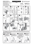
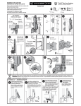
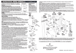
INSTALLATION INSTRUCTIONS
ENGLISH – North America
INSTALLATION INSTRUCTIONS
ENGLISH – International
For swimming and other child safety gates, most safety standards specify the
following minimum height requirements as being from the bottom of the gate:
1) latch release knob ‘F’ at minimum 54” (1370mm); 2) fence height of between 48” & 72” (1220 &
1830mm). Always confirm these and other requirements with the appropriate pool or safety authorities in your area and install
this latch in accordance with the local fence/barrier codes and regulations. Also, pool gate must open outward, away from the
pool, so this latch must be fitted to the outside of a pool gate. Tools: Electric and cordless drills, drill bits, Phillips No. 2 screwdriver
(hand & powered types). Note: If mounting to steel or vinyl with metal inserts, it is advisable to pre-drill the holes to prevent
screw breakage.
For swimming and other child safety gates, most safety standards specify the
following minimum height requirements above the finished ground/fixing surface:
1) latch release knob ‘F’ at minimum 1500mm (59”); 2) fence height of between 1220mm & 1520mm (48” & 60”)
Always confirm these and other requirements with the appropriate pool or safety authorities in your area and install this latch
in accordance with the local fence/barrier codes and regulations. Also, pool gate must open outward, away from the pool, so
this latch must be fitted to the outside of a pool gate. Tools: Electric or cordless drill, drill bits, Phillips No. 2 screwdriver (hand &
powered types). Note: For heavy gauge steel sections it is advisable to pre-drill the holes to prevent screw breakage.
Installation Procedure
Installation Procedure
1. The gap between gate frame and latch post must be between 3/8” (10mm) and 17/16” (37mm); 3/4” (19mm) is ideal.
2. Determine the location of the hole for Mounting Bracket ‘A’ by measuring up from the bottom of the gate,
1. The gap between gate frame and latch post must be between 10mm (3/8”) and 37mm (17/16”); 19mm (3/4”) is ideal.
2. Determine the location of the hole for Mounting Bracket ‘A’ by measuring up 1050mm (41 3/8”) from
3. To install Mounting Bracket ‘B’ measure up from Bracket ‘A’ 133/8” (340mm). Mark this point
3. To install Mounting Bracket ‘B’ measure up from Bracket ‘A’ 340mm (13 3/8”).
for 54” knob height measure up 363/8” (925mm).
Place Mounting Bracket ‘A’ on the post as shown, and, using one of the 1” (25mm) wafer-head,
self-drilling screws, fix the bracket to the post – through the side fixing hole. Now install two
more of these screws through the front of the bracket.
the finished ground/fixing surface.
Place Mounting Bracket ‘A’ on the post as shown, and, using one of the 25mm (1”) wafer-head,
self-drilling screws, fix the bracket to the post – through the side fixing hole. Now install two
more of these screws through the front of the bracket.
and fix as ‘2’ above.
NOTE: For 48” (1220mm) fences without an extra-high post, this measurement should be
5” (125mm) for 54” (1370mm) knob height from bottom of gate.
Place the Bracket ‘B’ so that the holes are centered on the marked line. Fix bracket
using the same screws as per Bracket ‘A’. (NOTE: In some applications it may be
necessary to add a spacer to clear a post cap. Spacers S1, S2 & S3 are for this
purpose and should be inserted behind the mounting brackets during
installation.)
Mark this point.
NOTE: For 1220mm (48”) fences without an extra-high post, this measurement should be
125mm (5”).
Place the Bracket ‘B’ so that the holes are centered on the marked line. Fix bracket
using the same screws as per Bracket ‘A’. (NOTE: In some applications it may be
necessary to add a spacer to clear a post cap. Spacers S1, S2 & S3 are for this
purpose and should be inserted behind the mounting brackets during
installation.)
4. Take the main LATCH BODY ‘C’
4. Take the main LATCH BODY ‘C’ and slide it down onto the
and slide it down onto the Mounting
Bracket ‘B’, ensuring the rear track of
the latch slides over brackets ‘B’, then ‘A’.
5. Slide the Latch Body until the bottom
of the latch aligns neatly with the lower
end of Bracket ‘A’ (see dashed line ‘L’).
Take the single 3/8” (10mm) countersunk screw ‘H’ and secure the Latch
Body – DO NOT use a power or cordless
drill – to Bracket ‘A’.
6. The final part to be installed is the
STRIKER BODY ‘D’. Note that the Striker
Body slides on a dovetail track within
the Mounting Plate (P1, P2). NEVER use
a powered drill to adjust this screw.
See Diagram ‘E’. Locate the Striker
Body assembly onto the post as shown.
Position the Striker Body to obtain a
1
/8” (3mm) gap between the lower part
of the latch and the top of the Striker
Body, as shown. Maintain this gap and
fix two 1” (25mm) screws through the
two main holes of the Striker Body.
The two, small (cylindrical) dress plugs
supplied should now be pressed into the
screw holes.
7. a) Open the gate and secure two more screws through the side leg of the Mounting Plate. Note: If the width of the gate
frame is 11/2” (38mm) or greater, follow step b)…
b) With the gate open, adjust the Striker Body using the screwdriver in the adjustment screw. Turn counter-clockwise until
the two holes are exposed, as in Diagram (P2). Fix the two remaining screws to secure the Mounting Plate.
8. Use the screwdriver to adjust the Striker Body to align with the Latch Body, as shown in Diagram ‘E’. Open and close the
gate to check the latch operates correctly. Adjust as necessary at any time after installation to ensure safe operation of the
latch. NOTE: Future vertical adjustment of the latch can be achieved by removing the screw ‘H’, sliding the Latch Body up or
down the post to obtain correct operational alignment, then inserting the screw into the appropriate hole.
Mounting Bracket ‘B’, ensuring the rear track of the latch
slides over brackets ‘B’, then ‘A’.
HIGH POST
used in some
markets
5. Slide the Latch Body until the bottom of the
latch aligns neatly with the lower end of
Bracket ‘A’ (see dashed line ‘L’). Take
the single 10mm (3/8”) countersunk
screw ‘H’ and secure the Latch Body –
DO NOT use a power or cordless drill
– to Bracket ‘A’.
NOTICE DE MONTAGE
F R A N ÇAIS – Canada
• Le système Magna Latch peut être utilisé sur les portillons des barrières de protection
de piscines privatives destinées à un usage familial ou collectif.
• Les barrières de protection de piscine sont destinées à limiter lʼaccès de la piscine à des enfants de moins de cinq ans.
• Il est recommandé dʼinstaller la barrière de protection à un mètre minimum du plan dʼeau. Pour les piscines privatives
à usage individuel, il est recommandé de ne pas installer la barrière trop loin du bassin afin de ne pas perdre lʼefficacité
de la barrière.
En matière de barrières de piscine et autres barrières de protection pour les enfants de moins de 5 ans, les normes
de sécurité spécifient entre autres :
1) une barrière d’une hauteur d’au moins 1100 mm (la hauteur minimale entre deux points d’appui doit
toujours être supérieure ou égale à 1100 mm)
2) un système de déverrouillage, en l’occurrence le bouton de déverrouillage, placé à
une hauteur supérieure à 1500 mm à partir du sol à l’extérieur de la zone
protégée.
Par ailleurs, lorsque le moyen d’accès choisi est
pivotant , l’ouverture doit se faire vers
l’extérieur de la piscine. De fait, la
serrure Magna-Latch doit être fixée sur
le côté extérieur de la barrière.
Il est impératif de demander confirmation de ces exigences et d’autres normes
éventuelles auprès des professionnels de
la piscine et des autorités en charge de
l’équipement ou de la sécurité de votre
région et d’installer cette serrure en
parfaite conformité avec les normes et
les réglementations len vigueur.
Outils : perceuse électrique ou sans fil,
mèches, tournevis Phillips No. 2 (manuel
& électrique). Note : pour les montants en acier de forte épaisseur, il est
conseillé d’effectuer un pré-perçage des
trous, afin d’éviter de briser les vis.
6. The final part to be installed is
the STRIKER BODY ‘D’. Note that the
Striker Body slides on a dovetail track
within the Mounting Plate (P1, P2) and
is operated by an internal adjustment
screw; NEVER use a powered drill to
adjust this screw.
See Diagram ‘E’. Locate the Striker Body
assembly onto the post as shown. Position the Striker Body to obtain a 3mm
(1/8”) gap between the lower part of
the latch and the top of the Striker Body,
as shown. Maintain this gap and fix two
25mm (1”) screws through the two main
holes of the Striker Body. The two, small
(cylindrical) dress plugs supplied should
now be pressed into the screw holes.
7. a) Open the gate and secure two
more screws through the side leg of the Mounting Plate. Note: If the width of the gate frame is 38mm (11/2”) or greater, follow
step b)…
b) With the gate open, adjust the Striker Body using the screwdriver in the adjustment screw. Turn counter-clockwise until the
two holes are exposed, as in Diagram (P2). Fix the two remaining screws to secure the Mounting Plate.
8. Use the screwdriver to adjust the Striker Body to align with the Latch Body, as shown in Diagram ‘E’. Open and close the gate
to check the latch operates correctly. Adjust as necessary at any time after installation to ensure safe operation of the latch.
NOTE: Future vertical adjustment of the latch can be achieved by removing the screw ‘H’, sliding the Latch Body up or down the
post to obtain correct operational alignment, then inserting the screw into the appropriate hole.
Swimming pool fences, gates and latches cannot substitute for adult supervision. If using this latch on a swimming pool gate, consult all appropriate local
authorities for safety requirements.
The latch will operate properly only if installed and maintained in accordance with these instructions.
Swimming pool fences, gates and latches cannot substitute for adult supervision. If using this latch on a swimming pool gate, consult all appropriate local authorities
for safety requirements.
The latch will operate properly only if installed and maintained in accordance with these instructions.
MAINTENANCE: REMOVE KEY FROM LOCK AFTER USE. Do not lubricate the latch with petroleum-based lubricants at any time; use only powdered graphite.
Ensure all screws or bolts are tightened firmly and that the release knob [F] and latching bolt are kept free of sand, ice and other debris which could impair latch
performance. Grind or remove any protruding fasteners after installation.
For a downloadable Adobe Acrobat (.PDF) version of our Limited LIFETIME WARRANTY,
go to our website at www.ddtechglobal.com
For a downloadable Adobe Acrobat (.PDF) version of our Limited LIFETIME WARRANTY,
go to our website at www.ddtechglobal.com
Procédure
d’installation
1. L’écart entre le cadre du portillon et le montant sur lequel sera
placée la serrure doit être compris
entre 10 mm et 37 mm, la distance
idéale étant de 19 mm.
2. Marquer lʼemplacement du trou
nécessaire au montage de la patte
de fixation A à 1100 mm du sol fini
ou de la surface de fixation.
Visser la patte de fixation A sur
le côté du montant de la barrière
comme indiqué sur le schéma, à l’aide de l’une des vis autoperforantes à tête wafer 25 mm. Finir de fixer
la patte de fixation à l’aide de deux autres vis semblables sur la face avant du montant.
3. Pour installer la patte de fixation B, tracer une ligne à 125 mm au-dessus de la patte de fixation A
(prendre pour repère la vis centrale de la patte de fixation A).
Positionner la patte de fixation B de manière à ce que les
trous soient centrés sur la ligne tracée, puis la fixer à l’aide du même type de vis que pour la patte de
•INSTR MLTP North America 29/11/12
MLINSTR0029PA
AUSTRALIA: Unit 6, 4-6 Aquatic Dr, Frenchs Forest NSW 2086
USA: 7731 Woodwind Drive, Huntington Beach, CA 92647
EUROPE: Niasstraat 1, 3531 WR Utrecht, The Netherlands.
www.ddtechglobal.com
F R A N ÇAIS – Canada
INSTALLATION
…suite de la page 1
fixation A. (NOTE : dans les cas où les montants de la barrière sont surmontés d’un capuchon, il peut s’avérer nécessaire lors du montage d’insérer derrière les pattes de fixation les pièces d’écartement S1, S2 et S3.)
4. Faire glisser la serrure C le long de la patte de fixation B, jusqu’à ce que son extrémité vienne parfaitement
s’aligner sur la partie inférieure de la patte de fixation A (voir ligne pointillée L), en veillant à ce que les rails situés
à l’arrière de la serrure glissent parfaitement le long des pattes de fixation B puis A.
5. Fixer la serrure à l’aide de la vis à tête fraisée 10 mm H sur la patte de fixation A. ATTENTION : NE PAS UTILISER
de visseuse électrique ou sans fil.
6. Le dernier élément à installer est la gâche D. Noter que la gâche glisse sur la plaque de montage à l’aide d’un
guide en queue d’aronde (P1, P2) et est actionnée par une vis de réglage interne ; NE JAMAIS utiliser de visseuse
électrique pour régler cette vis.
Placer la gâche sur le montant comme indiqué sur le schéma E, de manière à obtenir un intervalle de 3 mm entre
l’extrémité basse de la serrure et le haut de la gâche. Maintenir cet intervalle et fixer la gâche à l’aide de deux vis
de 25 mm sur la face avant du portillon. Insérer les deux petits cylindres de protection fournis dans les trous des
vis.
7. a) Ouvrir le portillon et finir de fixer la plaque de montage sur le côté du portillon à l’aide de deux autres vis.
Note : si la largeur du cadre du portillon est de 38 mm ou plus, voir étape b.
b) Lorsque le portillon est ouvert, ajuster la gâche à l’aide de la vis de réglage. Tourner dans le sens inverse des
aiguilles d’une montre jusqu’à ce que les deux trous apparaissent (diagramme P2). Finir de fixer la plaque de
montage à l’aide des deux vis restantes.
8. Ajuster à l’aide du tournevis la gâche de manière à ce qu’elle s’aligne sur la serrure, comme indiqué dans le
schéma E. Ouvrir et fermer le portillon afin de vérifier le bon fonctionnement de la serrure. Il est toujours possible
de réajuster la serrure après son installation afin de garantir un fonctionnement optimal.
NOTE : Pour le réglage vertical de la serrure, retirer la vis H et faire glisser la serrure vers le haut ou vers le bas
jusqu’à obtenir un alignement correct. Replacer ensuite la vis dans le trou le plus adapté.
E S P A Ñ O L – Norteamérica
E S P A Ñ O L – Norteamérica
INSTRUCCIONES DE MONTAJE
INSTRUCCIONES DE MONTAJE
Importante
…Continuación de la primera página
Para puertas para piscinas y otras puertas de seguridad para niños la mayoría de los estándares de seguridad
especifican los siguientes requisitos mínimos de altura medidos desde la base de la puerta:
1) tirador del pestillo de apertura ‘F’ a un mínimo de 54”(1370mm);
2) alto de la cerca de entre 48” y 72” (1220 y 1830mm)
Siempre confirme éstos y otros requisitos con las autoridades correspondientes
encargadas de las piscinas o de seguridad en su zona, e instale este pestillo
con arreglo a los códigos y reglamentos locales para cercas/barreras.
Además, el portón de la piscina deberá abrirse hacia afuera,
alejándose de la piscina, de manera que el pestillo deberá
colocarse en la parte exterior de un portón de piscina.
Herramientas necesarias: Taladros eléctricos o a pilas,
mechas para taladro, destornillador Phillips Nº 2
(para destornilladores manuales y eléctricos).
Observación: Si se efectúa el montaje a
acero o vinílico con tensores metálicos
se aconseja pre-perforar los
agujeros para evitar la rotura
del tornillo.
Procedimiento de
instalación
4. Tome el CUERPO o parte principal DEL PESTILLO ‘C’ y deslícelo sobre el Soporte de Montaje ‘B’, asegurando que
la guía trasera del pestillo se deslice sobre el soporte ‘B’, y luego sobre el soporte ‘A’.
5. Deslice el Cuerpo del Pestillo hasta que la parte inferior del pestillo coincida exactamente con la parte inferior
del Soporte ‘A’ (ver línea quebrada ‘L’). Tome el único tornillo de cabeza embutida de 3/8” (10mm) ‘H’ y asegure el
Cuerpo del Pestillo al Soporte ‘A’ -NO use taladro eléctrico ni a pilas -.
6. La parte final a instalar es el CUERPO DEL CERROJO ‘D’.
Note que el cuerpo del cerrojo calza en una guía de empalme con cola de milano en la Placa de Montaje P1, P2) y
que se opera con tornillo de ajuste interno; NUNCA use un taladro eléctrico para ajustar ese tornillo.
Ver Diagrama ‘E’. Coloque el ensamblaje del Cuerpo del Cerrojo sobre el poste, según se muestra. Ubique el Cuerpo
del Cerrojo de manera de obtener un espacio de 1/8” (3mm) entre la parte inferior del pestillo y la parte superior
del Cuerpo del Cerrojo, según se muestra. Mantenga dicho espacio y fije dos tornillos de 1” (25mm) a través de los
dos agujeros principales del Cuerpo del Cerrojo. Las dos tapitas (cilíndricas) que se proporcionan deberán aplicarse a
presión ahora en los agujeros de los tornillos.
7. a) Abra el portón y asegure dos tornillos más a través de
la pata lateral de la Placa de Montaje. Nota: Si el
ancho del marco del portón es de 1 /2” (38mm) o mayor, haga lo que se indica en b)…
b) Con el portón abierto, ajuste el Cuerpo del Cerrojo, utilizando el destornillador, con el tornillo de ajuste. Hágalo
girar en sentido contrario a las agujas del reloj hasta que aparezcan los dos agujeros, según el Diagrama (P2).
Fije los dos tornillos que le quedan, para asegurar la Placa de Montaje.
1
8. Use el destornillador para ajustar el Cuerpo del Cerrojo hasta que coincida con el Cuerpo del Pestillo, según
aparece en el Diagrama ‘E’. Abra y cierre el portón para verificar que el pestillo funcione correctamente.
De ser necesario, ajuste en cualquier momento después de la instalación, para asegurar el funcionamiento
seguro del pestillo.
NOTA: El ulterior ajuste vertical del pestillo puede lograrse quitando el tornillo ‘H’, deslizando el Cuerpo del
Pestillo hacia arriba o hacia abajo por el poste hasta obtener la correcta coincidencia de funcionamiento, y luego
insertando el tornillo en el agujero correspondiente.
1. El espacio entre el marco
del portón y el poste del
pestillo deberá ser de
entre 3/8” (10mm) y 17/16”
(37mm); 3/4” (19mm) es lo
ideal.
2. Determinar la ubicación
La protection apportée par les barrières de piscine, portillons et autres serrures ne remplace en aucun cas la
surveillance exercée par un adulte. Si vous désirez installer cette serrure sur le portillon d’une barrière de piscine,
renseignez-vous sur les exigences de sécurité auprès des autorités locales concernées. Le bon fonctionnement de la
serrure dépend uniquement d’une installation et d’une maintenance conformes aux présentes instructions.
MAINTENANCE : RETIRER LA CLE APRES UTILISATION. N’utiliser en aucune façon sur le verrou de lubrifiants pétroliers. Employer uniquement des produits
à base de graphite. Veiller à ce que l’ensemble des vis ou écrous soient correctement serrés et à ce que rien (sable, débris, glace…) ne vienne gêner le
fonctionnement du bouton de déverrouillage F ou du pêne, altérant ainsi la performance de la protection offerte par la serrure.
Pour obtenir une version Adobe Acrobat (.PDF) téléchargeable de notre GARANTIE À VIE limitée, visitez notre site Web à www.ddtechglobal.com
del agujero para el soporte de
montaje “A” midiendo hacia
arriba desde la base de la
puerta, para una altura de
tirador de 54”, mida 363/8”
(925mm); Coloque el Soporte
de Montaje ‘A’ sobre el poste
según se muestra, y,
utilizando uno de los tornillos
autoperforadores de cabeza
tipo pastilla de 1” (25mm), fije la placa al poste a través del agujero de fijación lateral. Ahora asegure dos más
de esos tornillos a través del frente del soporte.
Las cercas, portones y pestillos de las piscinas no sirven como substituto de la supervisión por parte de adultos. Si se usa este pestillo
en un portón de piscina, consulte a todas las autoridades locales correspondientes con respecto a los requisitos de seguridad. El pestillo
funcionará debidamente sólo si se instala y mantiene de acuerdo a estas instrucciones.
MANTENIMIENTO: QUITE LA LLAVE DE LA CERRADURA DESPUÉS DE USARLA. No lubrique el pestillo con lubricantes aceitosos en ningún
momento; use sólo grafito en polvo. Asegúrese de haber ajustado todos los tornillos o tuercas firmemente y que el tirador de apertura
[F] y el pestillo estén libres de arena, hielo u otros fragmentos que puedan impedir su eficaz funcionamiento. Esmerile o retire todo
elemento de que sobresalga después de la instalación.
Para un version de nuestra garantia limitada de por vida descargable en Adobe Acrobat (.pdf), vaya a nuestro sitio Web en www.ddtechglobal.com
3. Para instalar el Soporte de Montaje ‘B’ mida, desde el Soporte ‘A’, 133/8” (340mm). Marque ese punto y
fíjelo tal como en ‘2’, de más arriba.
Observación: Para cercas de 4 pies (1220mm) sin un poste extra alto, esa medida deberá ser de 5” (125mm)
para una altura de tirador de 54” (1370mm).
Coloque el Soporte ‘B’ de manera que los agujeros estén centrados sobre la línea marcada. Fije el soporte usando
los mismos tornillos que usó para el Soporte ‘A’. (NOTA: En algunas aplicaciones, quizás sea necesario agregar
un espaciador para evitar tocar la tapa del poste. Los espaciadores S1, S2 y S3 tienen ese objeto y deberán
insertarse detrás de los soportes de montaje durante la instalación.
…De vuelta la página por favor ➧
•INSTR MLTP North America 29/11/12
MLINSTR0029PA
AUSTRALIA: Unit 6, 4-6 Aquatic Dr, Frenchs Forest NSW 2086
USA: 7731 Woodwind Drive, Huntington Beach, CA 92647
EUROPE: Niasstraat 1, 3531 WR Utrecht, The Netherlands.
www.ddtechglobal.com