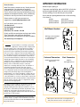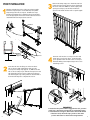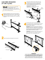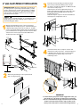
1
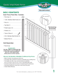
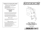
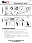
Installation Guide
U.S. Version
Tools & Materials Needed
• Hacksaw or metal cutting saw
• Drill
• Drill bits: 1/8", 1/4", 5/32", 7/32"
• 3/8" socket or wrench
• Phillips screwdriver
• Measuring tape
• Non-corrosive exterior silicone caulking
All fasteners are included with each component.
Self-drilling screw
Lag bolt
Phillips screw
Connector
Bolt
See WARNING on inside panel
peakproducts.com
Dear Customer,
We’d like to take a moment to say “thank you and
congratulations” for choosing our products.
At Peak™ your satisfaction is very important to us.
That is why we work very hard to provide you with
products of exceptional quality, value, and beauty.
And that is also why we want to hear from you.
Please contact us with your comments or
suggestions at: [email protected]
Or if you prefer, write to us at:
“Customer Care”
The Peak Group of Companies
P.O. Box 96060
Richmond, B.C. Canada V7A 5J4
Finally, we’d like to remind you to always work safely.
Then, take pride, relax with your family and
experience years of enjoyment with Peak™ products.
The Peak Group of Companies
WARNING No representation or warranty is given that
your particular application of these products complies with
relevant building codes or that the fasteners provided or
used are appropriate for your application. Consult with
professionals and local building officials before beginning
work: (i) to ensure compliance with relevant building codes
for your application and for your proposed use of fasteners;
(ii) to ensure the integrity of the structural components in
connection with which these products are to be used; (iii) to
identify appropriate safety gear that is to be used during
installation such as a safety harness when working above
ground; (iv) to ensure that the work area is free from
utilities, services and hazards; and (v) to clarify any
instructions or warnings that may not be clear. Work in a
safe manner wearing protective gear such as gloves,
eyewear, headwear, footwear and clothing. When using
tools comply with operation manuals and instructions. Metal
and glass may have sharp edges and could fragment or
splinter during or as a result of handling or cutting. Do not
use these products in connection with any substance that is
or may be harmful or corrosive to the products. Inspect and
maintain these products and the structural components that
they are used in connection with on a regular basis, using
professionals when appropriate.
IMPORTANT INFORMATION
Maximum post spacing: 6’
To prevent wood splitting and rot, drill 5/32" pilot holes
and coat lag bolt threads with non-corrosive exterior
silicone caulking. Ensure that the posts are plumb.
Ensure that the spacing between each of the following
is less than 4”:
· glass panels
· pickets
· glass panel and post
· pickets and post
· glass panel and wall
· pickets and wall
Wall Mount Brackets
Railings can be attached
to a wall using wall
mount brackets.
42 1/8"
2 3/8"
Universal Connectors
Used for horizontal angle
applications
Stair Connectors
Used for
Stair applications*
No member of The Peak Group of Companies (as defined at
www.peakproducts.com) shall be liable for any loss or
damage resulting from the improper installation or use of
this product. In the unlikely event that any member of The
Peak Group of Companies becomes liable for any loss or
damage, the aggregate liability shall be limited to the retail
purchase price of the product.
Peak products and associated materials are protected by
patents, designs, copyrights and/or trademarks used under
license from Peak Innovations Inc. P.O. Box 96060, Richmond
BC, Canada V7A 5J4.
2
* Glass panels cannot be used on stair applications.
Stair pickets must be used on stair applications.
3
PICKET INSTALLATION
Measure and mark the position of all posts and space equally.
Fasten the end post in place - ensure that the post is plumb.
Temporarily position the second post - do NOT secure it yet.
Cut the hand and base rails to fit between the posts. Install the
base rail support(s) into the bottom channel of the base rail and
install all but the last four spacers into each rail.
Remove the temporary post to install the last few
pickets and spacers. Cut the last spacers flush with
the ends of the rails. NOTE: to ensure equal picket
spacing at each post, cut the first and the last
spacers in the hand and base rails to equal lengths.
Handrail
Base rail
Base rail
support
Spacers
Insert the rails into the second post. Postion and
fasten the second post in place - ensure that the
post is plumb. Secure the rails to the second post
with self-drilling screws. Repeat Steps 1-4 for each
remaining section.
Insert the rails into the first post and secure these
rails to this post with self-drilling screws. Use the
second post as temporary support - do NOT secure the
rails to the second post yet. Slide the first spacer in each
rail against the first post. Insert a picket into the base
rail and swing the top of the picket into the handrail as
shown below. Repeat to complete the section.
IMPORTANT
To ensure that the pickets remain engaged in the rails, you must
install one or more base rail support(s) for each railing section.
To install the base rail support, insert it into the bottom channel
of the base rail (as shown in Step 1), slide it to the centre
position and secure it to deck surface using fasteners.
4
5
GLASS PANEL INSTALLATION
(18” wide or greater)
Always use two people to handle glass
panels. Always lift a glass panel by its sides.
Tempered glass is extremely fragile – do not bump the
edges. Always use protective gear including eyewear and
gloves when handling glass panels.
Measure and mark the position of all posts and space
equally. Fasten the end post in place - ensure the post is
plumb. Temporarily position the second post - do NOT
secure it yet. Cut the hand and base rails to fit between
the posts.
Cut the glass gaskets the same length as the rails
and drill 1/8" holes into the base rail glass gasket
for water drainage. Press the glass gaskets into
the rails and install the base rail support into the
bottom channel of the base rail.
IMPORTANT: The smaller of the two glass
gaskets goes into the Base rail.
Glass
gasket
Hand
rail
Base
rail
Base rail
support
Handrail
Insert the rails into the posts. Postion and fasten
the second post in place - ensure that the post is plumb.
Secure the rails to the posts with self-drilling screws.
(Refer to Step 4 on Page 5.)
Base rail
IMPORTANT: Ensure that the glass gaskets and the top
and bottom edges of the glass panel are well lubricated
with liquid soap before installing the glass panel. Install
the glass panel by inserting it into the handrail gasket
then lowering it into the base rail gasket.
IMPORTANT: Ensure that the glass is fully seated in the
gaskets. Wash away excess soap with clean water.
Repeat Steps 1-4 for each remaining section.
Remove the plastic picket gaskets from both rails.
Handrail
Base rail
Picket gasket
IMPORTANT
6
To ensure that the glass panel remains engaged in the rails,
you must install one base rail support for each railing section.
To install the base rail support, insert it into the bottom
channel of the base rail (as shown in step 3), slide it to the
centre position and secure it to deck surface using fasteners.
7
6” wide GLASS PANEL KIT INSTALLATION
IMPORTANT NOTICE: This kit was designed to fit perfectly in
a 6’ railing section. If your railing is shorter than 6’, you will
need to cut the spacers or remove glass panel(s) accordingly.
Distance between glass panels or glass panel and post must
never exceed 4”. The distance between a post and a glass
panel must never exceed 4”.
Always lift a glass panel by its sides.
Tempered glass is extremely fragile – do not bump the edges.
Always use protective gear including eyewear and gloves
when handling glass panels.
Insert the rails into the first post and secure these
rails to this post with self-drilling screws. Use the
second post as temporary support - do NOT secure the
rails to the second post yet.
Slide the spacer in each rail against the first post.
Remove the temporary support post and slide a glass
panel (with fittings attached) into the rails until
touching the spacers.
Slide the next pair of spacers into the hand and base
rails. Repeat to complete the section.
Measure and mark the position of all posts and space
equally. Fasten the end post in place - ensure that the post
is plumb. Temporarily position the second post - do NOT
secure it yet. Cut the hand and base rails to fit between the
posts. Install the base rail support into the bottom channel
of the base rail. Insert a spacer into the handrail and
another spacer into the base rail.
Handrail
Base rail
Insert the rails into the second post. Postion and
fasten the second post in place - ensure that the post
is plumb. Secure the rails to the second post with
self-drilling screws. Repeat Steps 1-4 for each
remaining section.
Base rail
support
Spacers
Attach the glass fittings to the top and bottom
ends of each glass panel.
IMPORTANT
To ensure that the glass panels remain engaged in the rails, you
must install one or more base rail support(s) for each railing
section. To install the base rail support, insert it into the bottom
channel of the base rail (as shown in Step 1), slide it to the
centre position and secure it to deck surface using fasteners.
8
9
STAIR RAILING INSTALLATION
Follow all applicable building codes for stair post placement and
heights of rails above nose of stair treads. NOTE: Stair pickets
and spacers are different from regular pickets and spacers. For
United States stair railing installations, regular hand and base
rails are not International Code Council compliant for graspability.
Always use stair hand and base rail set for stair applications.
Use Stair Connectors (SCs) at each post.
Drill 1/4" holes through the end caps and secure to the
backing plates with connector bolts. Position the base rail at
the required height above the nose of stair treads.
Position posts to meet base rail less than 8" above base.
Fasten the top post to the deck - ensure that the post is plumb.
Position and mark the location of the bottom post on landing or on
the last stair tread - do NOT secure yet.
With the base rail still in position, place the SCs on the posts to align
with the base rail. Remove the base rail and mark the locations of
the SCs on the posts. Drill 7/32" pilot holes into the posts and use the
flat head screws to attach bottom SCs to the posts.
Measure and cut the base rail to fit between the end caps.
Stair
Connectors
Backing
plate
End cap
Fig.1
BOTTOM POST
a
4" max.
b
Fig.2
Fig.3
4" Max.
TOP POST
Drill 1/4" hole
Max.8"
Cut the handrail to the same length as the base rail and fit
the SCs onto the handrail. Use two stair pickets to
position the handrail. Mark the locations of the SCs on the
posts. Remove the handrail from position and the SCs from the
handrail. Drill 7/32" pilot holes into the posts and use the flat head
screws to attach the SCs to the posts. Temporarily move the
bottom post to place the hand and base rails into the SCs.
Secure the SCs to the rails at the bottom post only.
10
Place a picket into both rails near the bottom post ensure that the picket is plumb and 4" or less from the
post. Starting from the bottom post, measure and cut the
end spacers then remove the picket (Fig. 1).
NOTE: At the bottom post, end spacer "a" will be shorter
than end spacer "b".
Temporarily move the bottom post and rails away from
the top post (Fig. 2). Install the end spacers followed by
pickets and stair spacers (step 2 of Picket Railing
Installation). Cut and install the last spacers flush with the
ends of rails. The last picket must also be 4" or less from
the top post (Fig. 3).
PRO TIP: To ensure equal spacing at each post, cut the first
and last spacers in the hand and base rails to a length that
ensures equal spacing between the end pickets and the posts.
Place the bottom post back into position and ensure that
the rails are fully inserted into the SCs at the top post.
Secure the hand and base rails to the SCs at the top post
as shown in step 2. Fasten the bottom post to the landing
or last stair tread - ensure that the post is plumb.
11
GATE INSTALLATION
Gate opening (W), must not exceed 46".
Remove the latch side of the gate (Fig. 1). Cut the top
and bottom gate rails 7 1/2" shorter than the gate
opening (Fig. 2). Align the top rail of the gate with the
handrails. Drill 5/32" pilot holes into the post and lag bolt
the gate to the post.
(Fig. 1)
Installati
U.S
(Fig. 2)
W ( 46" max)
W minus 7 1/2"
Tools & Materi
Use self-drilling screws for these steps:
- Secure the retainer to the gate frame at
marked position.
- Insert the latch through the retainer and
secure to the gate frame at marked position.
- Secure the latch side of the gate frame to
the top and bottom gate rails.
- Secure the latch plate.
• Hacksaw or metal c
• Drill
• Drill bits: 1/8", 1/4",
• 3/8" socket or wren
• Phillips screwdriver
• Measuring tape
• Non-corrosive exter
All fasteners are included
S
Latch
P
Retainer
L
Latch plate
C
B
Gate frame
See WARNING on ins
peakaluminu
12
PK_AR_ii_V2