1
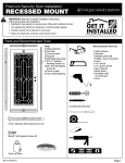
Ad va n ce d S c re e n Sys te m s Recessed Mount Ad va n ce d S c re e n Sys te m s Premium Security Screen Door Installation Instructions Ad va n ce d S c re e n Sys te m s Ad va n ce d S c re e n Sys te m s • • • • • Read completely through the installation instructions before proceeding with installation Ad va n ce d S c re e n Sys te m s Installation requires two people Use appropriate protective equipment, including safety glasses Children should not be allowed in work area Failure to install door correctly could result in injury RETAIN PACKAGING DURING INSTALLATION Do NOT discard packaging materials until installation is complete PROFESSIONAL INSTALLATION RECOMMENDED EASY HARD INSTALLATION Above average degree of difficulty. Requires installation experience. NEED HELP? REVIEW INSTALLATION VIDEO Even professional installers will benefit from watching. CONTACT US BEFORE RETURNING 3 2 1 4 3 2 4 RECOMMENDED TOOLS 1 2 3 4 5 6 7 8 10 12 15 18 24 5 [email protected] Customer service and technical support are available. Monday - Friday: 6:30am - 4pm PST 6 1-866-317-8867 85 75 30 65 55 45 35 25 15 5 MK1299 03202015 Level minimum length: 2-3/4" 1/2" Spade Bit 4 3 2 1 Phillips-head & Flat-blade screwdriver 2 Tin Snips 3 Box Cutter 4 Measuring Tape Drill Needle Nose Pliers 1 2 3 4 5 6 7 8 10 12 24 5 Safety Glasses Drill Bits 7/64" & 3/32" 18 6 Pencil 15 85 75 30 65 55 45 35 25 15 5 Square 1/2" Wood Chisel Rubber Mallet Wood Blocks (2"x4"x6") Shims Paintable Caulk & Caulk Gun Page 1 DOOR PARTS HARDWARE & FASTENERS A) Top header jamb A1) Top header jamb snap cover B) Hinge-side jamb B1) Hinge-side snap cover C) Security screen door D) Lock-side jamb D1) Lock-side snap cover E) Bug sweep F) Hinges (3) G) Latch guard H) #8x1" flat-head screws (14 pcs.) I) #6 x5/8" pan head screws (white - 10 pcs) J) #6x2" temporary dry wall screws (10 pcs) K) #14x3/4" pan head screws (2 pcs) L) #8x1" pan head screws (20 pcs) M) #6x5/8" self-tapping pan head screws (4) N) Screw cover caps (white - 2 pcs) O) Handles (2) P) Lock cylinder (1) Q) Latch strike plate (1) R) Latch hole plug (1) S) Throw protector (do not remove until step 7) T) Touch-up paint 3-1/2” flathead H I J 2” drywall 1” flathead K L 1/2” flathead 5/8” panhead M 3/4” panhead N 1” panh cap 3-1/2” flathead drywall flathead flathead panhead panhead 1”1” panhead 1-1/2” panhead 3-1/2” flathead 2” drywall 1”1/2” flathead 1/2” flathead 5/8” panhead panh 3-1/2” flathead 1”1” drywall 1” flathead 1/2” panhead flathead 5/8”panhead panhead 3/4” panhead 1” panhead 1-1/2”3/4” panhead 3-1/2” flathead 2”2” 2” drywall 1”2”flathead 1/2” flathead 5/8” 3/4” 1” panhead 1-1/2” panhead 3-1/2” flathead drywall flathead 1/2” flathead 5/8” panhead 3/4” panhead panhead 1-1/2” panhead 3-1/2”1/2” flathead 2”5/8” drywall 1” 3/4” flathead flathead 5/8” panhead 3/4” panhead 1” pa bumper A1 End plug A bumper bumper bumper bumper cap cap cap bumper cap bumper cap cap C F B1 B D O Q D1 G P S R T Active door - Double Cylinder P E Inactive door - Double Cylinder Page 2 1 Determining Identify and prepare Your Build mounting Out Area surface (continued) Inspect Your Entryway for Obstructions Check for any obstructions above and around your entryway that may prevent the outward swing of your new security door, and/or its installation, such as: Light fixtures Low overhang Door bell Trees, bushes, or hanging plants Determine Type and Readiness of Mounting Surface Your security door will require a minimum mounting surface of 1" on both sides of a corner of the trim or jamb above and on both sides of your entry door. Review diagrams at right and determine which one most resembles the trim around the entry door to which you will mount your security door. Measure Your Opening Measure between the edges of the left and right mounting surfaces for opening width. Measure between the edge of the upper mounting surface and the existing threshold for opening height. Use the following chart and these measurements to be sure the security door will fit your opening. Brick Moulding (Top View) Entry Door Stud Width (W) 32" x 80" 31 3/4" - 32 3/8" 36" x 80" 35 3/4" - 36 3/8" Stud Minimum 2-5/8" Brick moulding trim 1" minimum mounting surface 1" minimum mounting surface Ready for installation Flat Trim (Top View) Entry Door Stud Entry Door Jamb Stud Minimum 2-5/8" Flat Trim 1" minimum mounting surface 1" minimum mounting surface Ready for installation Sloped Trim (Top View) Entry Door Stud Entry Door Jamb Stud Minimum 2-5/8" Sloped Trim 1" minimum mounting surface Fits Door Opening Sizes Security Door Size Entry Door Jamb Additional sloped trim may be added in the reverse direction to create flat surface OR Sloped trim may be removed or replaced with flat trim to properly mount your new security door 1" minimum mounting surface Height (H) Stucco (Top View) 80" - 80 7/8" Entry Door Stud If the opening identified does not fall within the fit range, you can check to see if there is another mounting surface in your entryway that will work, build your mounting surface out using stop or similar trim, or remove and reconfigure your trim to fall within the fit range. Entry Door Jamb 1" minimum mounting surface Stud Minimum 2-5/8" Ready for installation Stucco Pop-out 1" minimum mounting surface CAUTION: Check closely for possible hardware interference! Check for Hardware Interference Measure the depth from the corner of your mounting surface to your existing entry door hardware. If this measurement is 2-5/8" or greater there is no potential for hardware interference. If the measurement is less than 2-5/8", measure from the edge of the mounting surface on top of the door to the top and bottom edge of the part of your existing hardware that intrudes into the 2-5/8" clearance. If either of these two measurements falls between 40-1/4" and 44-1/4", the security door and existing door hardware will interfere with each other. You can either build your mounting surface out to create the clearance required or mount your security door with an opposite swing to your main entry door. Entry Door Premium Security Door w/ Meshtec Screen Hinge-side jamb Lock-side jamb Page 3 1 2 Determining Determine swing Your Build Out Area (continued) 1 gniws enimreted determine swing B B TOP TOP C C hinge-side jamb latch-side jamb hinge-side jamb latch-side jamb Top View Top View C 1 3 2 Door Panel Rotation With top of door always remaining at the top, rotate door to left or right Latch-jamb positioning Cartwheel the latch jamb in to position on right or left of door depending on preferred swing B B C Determining Test fit frameYour and Build trim side Outjambs Area (continued) Place the top header jamb (A) and hinge-side jamb (B) into position. If the hinge-side jamb (B) is too long, mark with a pencil at the bottom (the jamb should sit on top of the threshold). Slide weather stripping up just above cut mark and trim jamb to length. A Follow same test fit and measurement procedure for the lock-side jamb (D). Trim to length if necessary. When jambs are trimmed to proper length slide the weather stripping flush to uncut end and trim excess from the cut end. B D trim to fit sits on top of threshold 1 4 Determining Assemble 3-piece Your Build frameOut Area (continued) On a clean flat surface (suggest cardboard or moving blanket to protect paint finish from scratching) place the top header jamb (A), hinge-side jamb (B) and lockside jamb (D) into position. Assemble the frame using #14x3/4" screws (K). Install screw at the top of each side jamb allowing the screw to protrude 1/8" (Fig. 1). Attach the top header jamb (A) to each side-jamb by sliding the screw into the slots on the top header jamb (A) (Fig. 2). Using a phillips-head screw driver tighten the screws the rest of the way in (Fig. 3). Fig. 2 Fig. 1 Fig. 3 If necessary trim weather stripping to length so it is a flush fit at each top corner of the frame. Page 4 1 5 Determining Install frame Your and prepare Build Out latch Area holes (continued) Place the assembled 3-piece frame inside the opening. Install two temporary mounting screws (#6x2" drywall screws (J)) on each side-jamb (B & D). One at the top and one at the bottom. These screws are inserted to temporarily hold the jambs in place. Do NOT install permanent screws until the door is completely up and working properly. Trace all 3 latch holes onto the mounting surface including top, bottom, and upper most of the two center latch holes. B ead 1” panh cap cap bumper head 1/2” flat ad 1” flathe bumper ll head 2” drywa 1/2” flat ad head 1” flathe 2” drywa ll 3-1/2” flat nhead nhead 3/4” pa 1-1/2” pa ead nhead 1” panh 5/8” pa D nhead 3/4” pa nhead 5/8” pa Remove temporary screws from lock-side jamb (D) ONLY and slide jamb away from opening to expose marks made on the mounting surface. Use a block to prop up the bottom of the latch-side jamb while preparing the latch holes. 1-1/2” pa nhead Prepare latch holes in mounting surface: D 1 6 Install latch strike plate (Q) to upper most center latch hole using #6x5/8" self-tapping pan-head screws (M) and install latch hole plug (R) into unused lower most center latch hole. head Re-install latch-side jamb using temporary screws. Do NOT install permanent screws. 3-1/2” flat Use a 1/2" wood chisel or spade drill bit (1/2") to clean the latch hole area out to a depth of 3/4". Chisel out a slightly larger area than marked to allow for adjustment if necessary. Determining Attach hingesYour andBuild hangOut door Area (continued) Door Side: Anti-bow point receiving hole Jamb Side: Anti-bow point Note: The Anti-bow point receiving hole lines up with the pre-drilled hole on the door. Place hinge (F) over pre-drilled holes on the door. The flat part of the hinge attaches to the door. The barrel side of the hinge should always be on the outside of the door. Use screws provided with the hinges and attach all 3 hinges to the door. Have a helper hold the door in place. It is important the door is held in proper alignment so the first mounting screw in each hinge is driven straight into the door panel. It may help to use blocks or similar props to assist in keeping the door properly aligned. Attach all 3 hinges to door using screws that attached hinges to jamb. CAUTION: Do NOT lay door on it's side so that it rests on the 3-point lock throws. This will cause the system to offset and you will need to remove and reset the locking system (see step 10). Page 5 1 7 Determining Remove throw Your protector Build Out Area (continued) Remove tape and discard throw protector (S). 1 8 Determining Install handleYour and Build lockset Out Area (continued) 1) Start on the interior side of the door. With the handle (O) facing toward the screen, insert the spindle and mounting screws through the mortise gear in the door panel. 2) On the exterior of the door with the handle pointing toward the screen, align the openings on the inside of the handle with the spindle and mounting screws. Position the handle against door frame. 3) While holding both handle trim plates in place, tighten the mounting screws and then back off 2 turns. These screws will be tightened after the lock cylinder is installed. Spindle 4) From the inside of the door, insert the lock cylinder (P) into the door through the trim plate. Using a Phillipshead screw driver, tighten the retainer screw until snug. Do NOT over-tighten. Tighten the two handle mounting screws until snug. Trim plate screw Spindle Trim plate screw 9 1 Lock cylinder Retainer screw Determining Test locking mechanism Your Build Out Area (continued) With the door open, retract the 3-point locking mechanism using the key or the thumb turn. Keep the door OPEN and test the mechanism by first depressing the 3-point locking system trigger, then deploying the locks using the key or thumb turn. If the locks will not deploy, the system has been offset and must be manually reset. Trigger If test is successful, install screw cover caps included with door handles on interior and exterior sides of door handles. If not, proceed to step 10 before installing screw cover caps. Page 6 10 1 Reset Determining lockingYour mechanism Build OutIFArea REQUIRED (continued) 1 2 Remove latch guard, if installed (4 mounting screws, 2 top, 2 bottom, on edge of door frame). 6 Remove cylinder by removing set screw through edge of door panel and pulling cylinder out of the door. 7 3 4 Remove handleset trim plates (2 mounting screws) – hold handles so they do not drop to floor. 8 5 Remove handles and spindle. 9 10 Re-install the lockset, spindle, handleset, cylinder, and latch guard (if removed) by reversing the removal procedure. Fully deployed Grab main throw with one hand and pull mortise lock part way out of edge of door. Place other hand BEHIND the black plastic linkage connector and keep pressure on it so that it stays connected to the mortise lock as you pull the mortise lock until it is almost out of the door. With one hand still keeping pressure on the connector so it remains attached to the lock, use the other hand to move the lockset down. Listen for it to click, the top and bottom lock throws will fully deploy. Remove the 2 mortise lock mounting screws in edge of door panel. Ensuring the linkage connecter stays attached to the back of the lockset, raise and slide the lockset back into the door panel. 11 1 Install Determining permanent Your Build mounting Out Area screws (continued) Hinge-side jamb (E): Pre-drill through mounting holes with 3/32"drill bit. Install permanent INSIDE screws (#8x1" flat-head screws (H)) into the INSIDE mounting holes (Fig. 4) checking that reveal stays even and 3-point locking trigger will engage as you install each screw. You may need to shim between the frame and mounting surface if tightening or loosening screws does not maintain the reveal and 3-point lock does not engage (Fig. 6 & Fig. 8). Lock-side jamb (D): Close the door. There should be a 1/8" reveal on the latch side. If necessary, place shim(s) between the door and frame to create the 1/8" reveal (Fig. 5). Pre-drill with 3/32"drill bit. Install OUTSIDE permanent screws (#8x1" pan-head screws (L))into all OUTSIDE mounting holes (Fig. 5). You may need to shim between the frame and mounting surface if tightening or loosening screws does not maintain the reveal and 3-point lock does not engage (Fig. 7 & Fig. 8). Install ALL remaining permanent screws INSIDE and OUTSIDE of hinge-side jamb, latch-side jamb and top-header jamb adjusting and/or shimming as described above. Fig. 4 Fig. 6 Fig. 5 If necessary, add shims here to make plumb and adjust reveal Fig. 7 If necessary, add shims here to make plumb and adjust reveal Top View (cutaway) Security Door Top View (cutaway) Security Door Mounting Screw Hinge-side Mounting Screw Lock-side Trigger Fig. 8 Page 7 12 1 Install Determining latch guard Your Build Out Area (continued) Attach the latch guard (G) provided in the hardware box to the door using four #6x5/8" pan head screws (I) in the pre-drilled holes. 13 1 Determining Install bug sweep Your Build Out Area (continued) Open the door. Slip the multi-blade bug sweep (E) onto the bottom of the door. Hold sweep in place and close the door. Allow the sweep to fall and sit resting on the esisting threshold. Note: Be sure there is not a gap between the sweep and the existing threshold and that the sweep is centered on the bottom of the door. Using the screws provided, attach the sweep to the bottom of the door. Test that the door opens and closes freely. If not, loosen the screws and make necessary adjustments. Re-tighten screws and test again. Repeat until successful. Cover screw heads with screw cover caps (N) provided. 14 1 Determining Install snap covers Your Build Out Area (continued) Place the snap cover (A1) in the top-header jamb (Fig. 9, step 1).Using a rubber mallet, hit on the side of snap cover seen in (Fig. 10) to securely snap cover into place. Once snap cover is secured, hold a wood block over the length of the snap cover and hit with mallet to smooth any irregularities in the snap cover surface. Repeat process for the hinge-side (B1) and lock-side (D1) snap covers. Fig. 9 Fig. 10 2 Door jamb Fully seated Snap cover 1 Page 8 Final touch-up suggestions 1 Caulk (not included) Caulk around the outside of the security door jamb frame, using paintable caulk, and paint to the desired color. 2 White Grease Lubricant (not included) Use white grease to lubricate the hinges of your new security door. Care and maintenance Over time, airborne dust, dirt, and impurities can accumulate, which will cause visual defects to your Meshtec screen and, if not regularly and properly removed, can lead to further damage, staining, and corrosion. Your cleaning schedule depends upon your environment: Environment Description Cleaning Schedule Mild Inland, rural, and away from industry and urban activity every 6 months Moderate Urban/suburban, inland, and away from heavy industry every 3 months Urban/suburban, coastal (within 25 miles), or near heavy industry every 2-4 weeks Extreme Thoroughly wash the screen and door frame using a soft cloth, mild soap, and water. Take care to avoid exposing handles, main lock, and 3-point locks to excessive amounts of water. Using a dry, soft cloth, remove any excess water when done. Pay particular attention to drying the screen to frame attachment area fully. Avoid using any sharp objects or abrasive materials on the door frame or screen. Use white grease to lubricate the hinges at each cleaning. Warranty Your Unique Home Designs security door with Meshtec Advanced Screen System is warranted against manufacturer defects under normal, residential use for the first 10 years you own the product, and terminates if you sell or otherwise transfer the product or the property upon which it was installed. An additional 5 years warranty protection is awarded (for 15 year total warranty) when the product is registered on-line at uniquehd.com/registration. Bug sweeps, weather-stripping, composite materials, and hardware included with or installed on the security door are covered for one year from date of purchase. Accessories fitted to the security door are not covered by this warranty, including but not limited to locks, handles, rollers, and closers. These accessories may be covered by warranties provided by the manufacturer or supplier of the products. Any problem caused by abuse, misuse, failure to follow care and maintenance instructions, adjustments due to settling of the structure that the product is mounted on, improper installation, or acts of God are not covered. Cutting parts not specified by the installation guide and parts drilled incorrectly are not included in this warranty. If manufacturer defects occur, Unique Home Designs will, at our discretion, either repair or replace the door. If your home is burglarized and entry was accomplished through a UHD security door, locked with the 3 point locking system, while this warranty is in effect, UHD will pay your insurance deductible up to $1000 or replace, as applicable, the damaged UHD security door at no charge. Replacement items may vary in style due to changes in suppliers and product. Not all colors can be reproduced if colors have been discontinued. UHD is not responsible for any labor expense required to repair or replace the door. UHD is not responsible for securing the property while warranted items are being repaired or replaced. To make a claim under this Warranty, send a brief written description of the problem, a picture of the claim, proof of purchase, and your contact information to: Unique Home Designs, 973 N. Colorado Street, Gilbert AZ. 85233 Attn.: Warranty Claims "Meshtec" is the registered Trade Mark of Meshtec International Co., Ltd. (‘MTC’) in the United States and other various worldwide jurisdictions (including registrations pending) and may not be used without the prior written consent of MTC. Extend Your Warranty! When you register on-line at uniquehd.com/registration Page 9