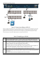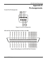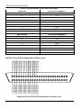
1
VES-1000 Series
VDSL-Ethernet Switches
May 2002
Version 3.40
Hardware Installation Guide
VES-1000 Series Ethernet Switch
Copyright
VES-1000 Series of VDSL-Ethernet Switches
Copyright © 2002 by ZyXEL Communications Corporation.
The contents of this publication may not be reproduced in any part or as a whole, transcribed, stored in a retrieval
system, translated into any language, or transmitted in any form or by any means, electronic, mechanical, magnetic,
optical, chemical, photocopying, manual, or otherwise, without the prior written permission of ZyXEL
Communications Corporation.
Published by ZyXEL Communications Corporation. All rights reserved.
Disclaimer
ZyXEL does not assume any liability arising out of the application or use of any products, or software described
herein. Neither does it convey any license under its patent rights nor the patent rights of others. ZyXEL further
reserves the right to make changes in any products described herein without notice. This publication is subject to
change without notice.
Trademarks
Trademarks mentioned in this publication are used for identification purposes only and may be properties of their
respective owners.
ii
Copyright
VES-1000 Series Ethernet Switch
ZyXEL Limited Warranty
ZyXEL warrants to the original end user (purchaser) that this product is free from any defects in materials or
workmanship for a period of up to two (2) years from the date of purchase. During the warranty period and upon
proof of purchase, should the product have indications of failure due to faulty workmanship and/or materials,
ZyXEL will, at its discretion, repair or replace the defective products or components without charge for either parts
or labor and to whatever extent it shall deem necessary to restore the product or components to proper operating
condition. Any replacement will consist of a new or re-manufactured functionally equivalent product of equal
value, and will be solely at the discretion of ZyXEL. This warranty shall not apply if the product is modified,
misused, tampered with, damaged by an act of God, or subjected to abnormal working conditions.
Note
Repair or replacement, as provided under this warranty, is the exclusive remedy of the purchaser. This warranty is
in lieu of all other warranties, express or implied, including any implied warranty of merchantability or fitness for a
particular use or purpose. ZyXEL shall in no event be held liable for indirect or consequential damages of any kind
of character to the purchaser.
To obtain the services of this warranty, contact ZyXEL's Service Center for your Return Material Authorization
number (RMA). Products must be returned Postage Prepaid. It is recommended that the unit be insured when
shipped. Any returned products without proof of purchase or those with an out-dated warranty will be repaired or
replaced (at the discretion of ZyXEL) and the customer will be billed for parts and labor. All repaired or replaced
products will be shipped by ZyXEL to the corresponding return address, Postage Paid. This warranty gives you
specific legal rights, and you may also have other rights that vary from country to country.
ZyXEL Limited Warranty
iii
VES-1000 Series Ethernet Switch
Customer Support
If you have questions about your ZyXEL product or desire assistance, contact ZyXEL Communications
Corporation offices worldwide, in one of the following ways:
Contacting Customer Support
When you contact your customer support representative, have the following information ready:
♦ Model and serial number.
♦ Warranty information.
♦ Date you received your product.
♦ Brief description of the problem and the steps you took to solve it.
METHOD
LOCATION
WORLDWIDE
E-MAIL: SUPPORT
TELEPHONE
WEB SITE
SALES
FAX
FTP SITE
[email protected]
+886-3-578-3942
www.zyxel.com
www.europe.zyxel.com
NORTH
AMERICA
SCANDINAVIA
GERMANY
MALAYSIA
iv
[email protected]
+886-3-578-2439
ftp.europe.zyxel.com
[email protected]
+1-714-632-0882
www.zyxel.com
800-255-4101
REGULAR MAIL
ZyXEL Communications
Corp., 6 Innovation Road
II, Science-Based
Industrial Park, Hsinchu,
300, Taiwan.
ZyXEL Communications
Inc., 1650 Miraloma
Avenue, Placentia, CA
92870, U.S.A.
[email protected]
+1-714-632-0858
ftp.zyxel.com
[email protected]
+45-3955-0700
www.zyxel.dk
[email protected]
+45-3955-0707
ftp.zyxel.dk
[email protected]
+49-2405-6909-0
www.zyxel.de
[email protected]
+49-2405-6909-99
ZyXEL Deutschland
GmbH. Adenauerstr.
20/A4 D-52146
Wuerselen, Germany.
[email protected]
+603-795-44-688
www.zyxel.com.my
[email protected]
+603-795-34-407
Lot B2-06, PJ Industrial
Park, Section 13, Jalan
Kemajuan, 46200
Petaling Jaya Selangor
Darul Ehasn, Malaysia
ZyXEL Communications
A/S, Columbusvej 5, 2860
Soeborg, Denmark.
Customer Support
VES-1000 Series Ethernet Switch
Table of Contents
Copyright....................................................................................................................................................................................... ii
ZyXEL Limited Warranty ............................................................................................................................................................. iii
Customer Support ....................................................................................................................................................................... iv
Table of Contents.......................................................................................................................................................................... v
List of Diagrams......................................................................................................................................................................... viii
List of Tables.............................................................................................................................................................................. viii
Preface.......................................................................................................................................................................................... ix
Chapter 1
1.1
VES-1000 Series Switch Applications................................................................................................................ 1-1
Applications ............................................................................................................................................... 1-1
1.1.1
MTU Application .............................................................................................................................. 1-1
1.1.2
Enterprise Application....................................................................................................................... 1-2
1.1.3
Campus Applications ........................................................................................................................ 1-3
Chapter 2
Hardware Installation........................................................................................................................................... 2-1
2.1
Operating Environment ............................................................................................................................. 2-1
2.2
Installing the VES-1008............................................................................................................................. 2-1
2.2.1
Free-standing..................................................................................................................................... 2-1
2.2.2
Rack-mounted ................................................................................................................................... 2-1
2.2.3
Wall Mounted.................................................................................................................................... 2-3
2.3
Installing the VES-1012............................................................................................................................. 2-4
2.3.1
Free-standing..................................................................................................................................... 2-4
2.3.2
Rack-mounted ................................................................................................................................... 2-4
Chapter 3
Installation Scenarios .......................................................................................................................................... 3-1
3.1
Overview.................................................................................................................................................... 3-1
3.2
Telco Cables .............................................................................................................................................. 3-2
3.3
MDF (Main Distribution Frame) ................................................................................................................. 3-2
3.4
Typical Scenarios ...................................................................................................................................... 3-3
3.4.1
Installation Scenario A ...................................................................................................................... 3-3
3.4.2
Installation Scenario B ...................................................................................................................... 3-4
3.4.3
Installation Scenario C ...................................................................................................................... 3-7
Chapter 4
Hardware Connections ........................................................................................................................................ 4-1
Table of Contents
v
VES-1000 Series Ethernet Switch
4.1
Rear Panel Connections............................................................................................................................ 4-1
4.1.1
4.2
Power Cord........................................................................................................................................4-1
Front Panel Connections ........................................................................................................................... 4-2
4.2.1
Console Port ......................................................................................................................................4-3
4.2.2
VDSL Ports Connections ..................................................................................................................4-4
4.2.3
WAN Port (Ethernet) Connections....................................................................................................4-4
Chapter 5
Turning On Your VES-1000 Series Switch......................................................................................................... 5-1
5.1
Introduction ................................................................................................................................................ 5-1
5.2
Front Panel LEDs ...................................................................................................................................... 5-1
Chapter 6
Hardware Troubleshooting ................................................................................................................................. 6-1
System Startup ...................................................................................................................................................... 6-1
6.1.1
My PWR LED Does Not Turn On ....................................................................................................6-1
6.1.2
My SYS LED Does Not Turn On......................................................................................................6-1
The ALM LED Is On............................................................................................................................................... 6-2
6.2
A PORT LED Does Not Turn On................................................................................................................ 6-2
6.3
The WAN Link is down .............................................................................................................................. 6-3
6.4
Testing Wiring ............................................................................................................................................ 6-3
Appendix A Removing and Installing a Fuse .............................................................................................................................A
Appendix B Pin Assignments......................................................................................................................................................C
Appendix C Hardware Specifications .........................................................................................................................................G
Index .............................................................................................................................................................................................. 1
vi
Table of Contents
VES-1000 Series Ethernet Switch
List of Figures
Figure 1-1 Building Deployment Example Using a VES-1012...................................................................................................1-2
Figure 1-2 Enterprise Application Using a VES-1012 ................................................................................................................1-3
Figure 1-3 VES-1012 Example of a Campus Application Using a Gigabit switch .....................................................................1-4
Figure 1-4 VES-1012 Example of Campus Application Using a Fiber Ring ..............................................................................1-4
Figure 2-1 Attaching the Mounting Brackets to the VES-1008...................................................................................................2-2
Figure 2-2 Mounting the VES-1008 in a Rack............................................................................................................................2-3
Figure 2-3 Attaching the Wall-mounting brackets to the VES-1008 ...........................................................................................2-4
Figure 2-4 Attaching the Mounting Brackets to the VES-1012...................................................................................................2-5
Figure 2-5 Mounting the VES-1012 in a Rack............................................................................................................................2-6
Figure 3-1 Installation Overview for a VES-1012 ......................................................................................................................3-1
Figure 3-2 Telco Cable ................................................................................................................................................................3-2
Figure 3-3 MDF (Main Distribution Frame) Wiring ...................................................................................................................3-3
Figure 3-4 Installation Scenario A Using a VES-1012 ................................................................................................................3-4
Figure 3-5 One MDF for End-user and CO Connections............................................................................................................3-5
Figure 3-6 Installation Scenario B using VES-1012 ...................................................................................................................3-6
Figure 3-7 Two Separate MDFs for End-user and CO Connections ...........................................................................................3-7
Figure 3-8 Installation Scenario C using the VES-1012..............................................................................................................3-8
Figure 4-1 The VES-1012 Rear Panel .........................................................................................................................................4-1
Figure 4-2 Connecting the Power Cord to the VES-1012 and a Power Source...........................................................................4-2
Figure 4-3 VES-1008 Front Panel Connections Overview .........................................................................................................4-2
Figure 4-4 VES-1012 Front Panel Connections Overview .........................................................................................................4-3
Figure 4-5 Console Port Connection ...........................................................................................................................................4-3
Figure 4-6 Stacking the VES-1012..............................................................................................................................................4-5
Figure 4-7 Daisy-chaining Connections ......................................................................................................................................4-5
Figure 5-1 VES-1008 Front Panel...............................................................................................................................................5-1
Figure 5-2 VES-1012 Front Panel...............................................................................................................................................5-1
Figure 6-1 Testing In-house Wiring on a VES-1012 ...................................................................................................................6-4
Lists of Figures, Diagrams and Tables
vii
VES-1000 Series Ethernet Switch
List of Diagrams
Diagram 1 Removing the Power Cord .......................................................................................................................................... A
Diagram 2 Opening the Fuse Housing ...........................................................................................................................................B
Diagram 3 Fuses in the Fuse Housing............................................................................................................................................B
Diagram 4 Console Port Assignments............................................................................................................................................C
Diagram 5 Wiring Diagram for the VES-1008 Telco-50 connector...............................................................................................C
Diagram 6 VES-1012 Telco-50 Pin Assignments for Phone Lines ............................................................................................... D
Diagram 7 VES-1012 Telco-50 Pin Assignments for VDSL Connections.....................................................................................E
List of Tables
Table 5-1 VES-1000 Series Switches: LED Descriptions........................................................................................................... 5-2
Table 6-1 PWR LED Troubleshooting ........................................................................................................................................ 6-1
Table 6-2 SYS LED Troubleshooting ......................................................................................................................................... 6-1
Table 6-3 ALM LED Troubleshooting ........................................................................................................................................ 6-2
Table 6-4 PORT LED Troubleshooting....................................................................................................................................... 6-2
Table 6-5 Testing Wiring on a VES-1008 ................................................................................................................................... 6-4
Table 6-6 Testing Wiring on a VES-1012 ................................................................................................................................... 6-5
Table 6-7 Pin Assignments for VES-1008 Telco-50 port .............................................................................................................. D
viii
Lists of Figures, Diagrams and Tables
VES-1000 Series Ethernet Switch
Preface
Congratulations on your purchase from the VES-1000 Series of VDSL-Ethernet Switches.
This guide shows you how to set up the hardware for your VES-1000 Series Switch.
About VDSL
VDSL (Very high bit rate Digital Subscriber Line) is one type of DSL with very high data rates. The service can
be asymmetrical or symmetrical and can be used on the same wire as the POTS (Plain Old Telephone Service)
network and ISDN.
About the VES-1000 Series
The VES-1000 Series of VDSL-Ethernet Switches delivers high-performance broadband access at low cost to
multi-tenant unit (MTU) buildings (hotels, motels, resorts, residential multi-dwelling units, office buildings,
university campuses, etc.) and public facilities, such as convention centers, airports, plazas, and train stations. It
attains speeds ranging from 1.56 Mbps to 16.67 Mbps upstream and 4.17 Mbps to 16.67 Mbps downstream at
distances of up to 1.5 Km (5,000 feet) delivered over ordinary telephone lines.
There are currently two models in the VES-1000 Series of Ethernet Switches. The compact VES-1008 (one rackunit (1U) high) can be mounted on a wall or placed on a rack. It has built-in voice-signal splitters for added system
stability. In addition to remote management capability, a console port is used for local management. This 8-port
switch is equipped with VLAN (Virtual LAN) capability that can isolate each port. You can connect up to 8
subscriber devices such as VDSL converters to this switch (ports 1 to 8). The VES-1012 extends on the flexibility
of the VES-1008 as it provides 12 ports that allow for the connection of up to 12 individual subscribers.
This hardware installation guide caters for both models.
Syntax Conventions
“Enter” means for you to type one or more characters and press the carriage return. “Select” or “Choose” means
for you to select one from the predefined choices.
For brevity’s sake, we will use “e.g.” as shorthand for “for instance”, and “i.e.” as shorthand for “that is” or “in
other words” throughout this manual.
Unless specified, images of the VES-1012 are used throughout this document. The VES-1008 has 8 available
Ethernet ports however the images used in this User’s Guide show the 12 available ports that are featured on the
VES-1012. Images that directly relate to the VES-1008 are used when referring to the key differences between
the two models.
Related Documentation
User’s Guide
The User’s Guide explains firmware setup, management and maintenance procedures.
ZyXEL Web Site
Please refer to www.zyxel.com for an online glossary of networking terms and additional support documentation.
Preface
ix
VES-1000 Series Ethernet Switch
Chapter 1
VES-1000 Series Switch Applications
This chapter describes the applications and basic operating environment for the VES Ethernet Switches.
1.1 Applications
The VES-1008 supports 8 VDSL ports as well as a combined USER/CO Telco connector. Expanding on this
flexibility, the VES-1012 features 12 VDSL ports as well as separate CO and USER Telco-50 connectors. The
applications and operating environment (and associated diagrams) presented in this chapter primarily focus on the
VES-1012; however, they are equally applicable for the VES-1008.
The following are typical applications for the VES-1000 Series of switches:
1. Multiple Tenant Unit (MTU)
2. Enterprise
3. Campus
1.1.1
MTU Application
The following figure depicts a typical application for a VDSL-Ethernet Switch in a large residential building, or
Multiple Tenant Unit (MTU), that leverages existing phone line wiring to provide Internet access to all tenants.
A tenant connects a computer to the phone line in a unit using a VDSL modem. The other end of the phone line is
connected to a port on a VES-1000 Series switch. The VES-1000 Series switch aggregates the traffic from the
tenants to the Ethernet port and forwards it to a router or switch. The router (or switch) then routes the traffic
further to the Internet.
Applications
1-1
VES-1000 Series Ethernet Switch
Figure 1-1 Building Deployment Example Using a VES-1012
1.1.2
Enterprise Application
The VES-1000 Series of switches can also be used in enterprises to multiplex employee traffic to the Internet.
1-2
Applications
VES-1000 Series Ethernet Switch
Figure 1-2 Enterprise Application Using a VES-1012
1.1.3
Campus Applications
Independent networks can also have traffic multiplexed to a gigabit switch or fiber ring using a VES-1000 Series
switch.
Applications
1-3
VES-1000 Series Ethernet Switch
Figure 1-3 VES-1012 Example of a Campus Application Using a Gigabit switch
Figure 1-4 VES-1012 Example of Campus Application Using a Fiber Ring
1-4
Applications
VES-1000 Series Ethernet Switch
Chapter 2
Hardware Installation
This chapter shows you how to install the VES-1000 Series switch in a free-standing, rack-mounted or
wall mounted scenario
2.1 Operating Environment
The following is the recommended environment for both the VES-1008 and VES-1012 Ethernet switch.
Operating Environment
•
Temperature: 0ºC — 50ºC
•
Humidity: 5% — 95%
Storage Environment
•
Temperature: -25ºC — 70ºC
•
Humidity: 5% — 95%
Refer also to the Hardware Specification Appendix.
2.2 Installing the VES-1008
2.2.1
Free-standing
Position the VES-1008 on a flat surface. Make certain that the unit has adequate ventilation.
2.2.2
Rack-mounted
Please note that rack-mounted is optional for the VES-1008. As a result, rack-mounted accessories are not
supplied.
•
Two mounting brackets (optional).
•
Eight M3 flat head screws (optional) and a #2 Philips screwdriver.
•
Four M5 flat head screws and a #2 Philips screwdriver.
Before you proceed with mounting the VES-1000 Series switch in a rack, please take note of the following
precautions:
Precautions:
•
Make sure the rack will safely support the combined weight of all the equipment it contains.
Hardware Installation
2-1
VES-1000 Series Ethernet Switch
•
Step 1.
Make sure the position of the VES-1008 does not make the rack unstable or top-heavy. Take all
necessary precautions to anchor the rack securely before installing the unit.
Position a mounting bracket on one side of the VES-1008, lining up the four screw holes on the bracket
with the screw holes on the side of the unit (Figure 2-1).
Failure to use the proper screws may damage the unit.
Step 2.
Using a #2 Philips screwdriver, install the M3 flat head screws that came with the brackets through the
mounting bracket holes into the VES-1008.
Step 3.
Repeat Step 1 and Step 2 to install the second mounting bracket on the other side of the unit.
Figure 2-1 Attaching the Mounting Brackets to the VES-1008
You may now mount the VES-1008 in a rack.
Step 1.
Position a mounting bracket (that is already attached to the VES-1008) on one side of the rack, lining up
the two screw holes on the bracket with the screw holes on the side of the rack (Figure 2-2).
Failure to use the proper screws may damage the unit.
Step 2.
Using a #2 Philips screwdriver, install the M5 flat head screws through the mounting bracket holes into
the rack.
Step 3.
Repeat Step 1 and Step 2 to attach the second mounting bracket on the other side of the rack.
2-2
Hardware Installation
VES-1000 Series Ethernet Switch
Figure 2-2 Mounting the VES-1008 in a Rack
2.2.3
Wall Mounted
The VES-1008 is designed so that it can be mounted on a wall if the need arises. The following is needed in order
to mount the VES-1008 on a wall:
•
Two mounting brackets (supplied).
•
Eight M3 flat head screws (supplied) and a #2 Philips screwdriver.
•
Four M5 flat head screws and a #2 Philips screwdriver.
Before you mount the VES-1008, please take note of the following precautions:
Precautions
Step 1.
•
Make certain that the intended position for the VES-1008 is strong enough to support the combined
weight of the unit and the cables. It is strongly recommended that you position the VES-1008 so
that the brackets are screwed into an upright beam, or stud, that is located within the wall.
•
Make certain that when mounted, you will be able to safely insert the Telco-50 cable along with the
power supply and then be able to safely monitor and observe the LEDs on the VES-1008.
Position a mounting bracket on one side of the VES-1008, lining up the four screw holes on the bracket
with the screw holes on the side of the unit (Figure 2-3).
Hardware Installation
2-3
VES-1000 Series Ethernet Switch
Figure 2-3 Attaching the Wall-mounting brackets to the VES-1008
Step 2.
Using a #2 Philips screwdriver, install the M3 flat head screws that came with the brackets through the
mounting bracket holes into the VES-1008.
Step 3.
Repeat Step 1 and Step 2 to install the second mounting bracket on the other side of the unit.
You may now mount the VES-1008 on the wall.
Step 4.
Position the VES-1008 flat against the wall and screw the mounting brackets directly to the wall. Make
certain that at least one of the mounting brackets is screwed into an upright beam, or stud, that is located
within the wall. This ensures that the combined weight of the VES-1008 and the cables will not force
any extra pressure on the actual wall.
Step 5.
Plug the Telco-50 cable and the power supply into the unit and make certain that all cables are safely
positioned and that you are able to easily monitor and observe the LEDs.
2.3 Installing the VES-1012
2.3.1
Free-standing
Position the VES-1012 on a flat surface. Make certain that nothing obstructs the cooling fans and that the unit has
adequate ventilation.
2.3.2
Rack-mounted
•
2-4
Two mounting brackets (supplied).
Hardware Installation
VES-1000 Series Ethernet Switch
•
Eight M3 flat head screws (supplied) and a #2 Philips screwdriver.
•
Four M5 flat head screws and a #2 Philips screwdriver.
Before you proceed with mounting the VES-1000 Series switch in a rack, please take note of the following
precautions:
Precautions:
Step 1.
•
Make sure the rack will safely support the combined weight of all the equipment it contains.
•
Make sure the position of the VES-1012 does not make the rack unstable or top-heavy. Take all
necessary precautions to anchor the rack securely before installing the unit.
Position a mounting bracket on one side of the VES-1012, lining up the four screw holes on the bracket
with the screw holes on the side of the unit (Figure 2-4).
Failure to use the proper screws may damage the unit.
Step 2.
Using a #2 Philips screwdriver, install the M3 flat head screws that came with the brackets through the
mounting bracket holes into the VES-1012.
Step 3.
Repeat Step 1 and Step 2 to install the second mounting bracket on the other side of the unit.
Figure 2-4 Attaching the Mounting Brackets to the VES-1012
You may now mount the VES-1012 in a rack.
Step 4.
Position a mounting bracket (that is already attached to the VES-1012) on one side of the rack, lining up
the two screw holes on the bracket with the screw holes on the side of the rack (Figure 2-5).
Failure to use the proper screws may damage the unit.
Step 5.
Using a #2 Philips screwdriver, install the M5 flat head screws through the mounting bracket holes into
the rack.
Step 6.
Repeat Step 1 and Step 2 to attach the second mounting bracket on the other side of the rack.
Hardware Installation
2-5
VES-1000 Series Ethernet Switch
Figure 2-5 Mounting the VES-1012 in a Rack
2-6
Hardware Installation
VES-1000 Series Ethernet Switch
Chapter 3
Installation Scenarios
This chapter details how to connect VDSL wiring to MDFs based on your existing telephone wiring
infrastructure.
3.1 Overview
Unless specified, images of the VES-1012 are used throughout this chapter. The VES-1008 has 8 VDSL ports as
well as a combined USER/CO Telco connector; however, the VES-1012 features 12 VDSL ports as well as
separate CO and USER Telco-50 connectors.
It should be noted that although the VES-1012 is shown in the following diagrams, the following scenarios can
also apply to the VES-1008 - the primary difference is that a single Telco-50 cable is used for the combined
USER/CO signal on the VES-1008. Installation instructions for the following scenarios are given for both the
VES-1008 and the VES-1012.
Figure 3-1 gives an overview on a possible installation scenario for the VES-1012. Data and voice signals can
coexist on the same telephone lines.
Figure 3-1 Installation Overview for a VES-1012
You can also attach RJ-11 connectors to the Telco cable and connect directly to a P841 VDSL
modem(s) or patch panel. This chapter discusses connections using MDFs.
Installation Scenarios
3-1
VES-1000 Series Ethernet Switch
3.2 Telco Cables
Telco cables are used for data and voice applications with MDFs (Main Distribution Frame), patch panels and
distribution boxes. They can also be used as extension cables. Telco cables are typically made up of 25 or 50
twisted-pair copper wires.
Connect a Telco connector to one end of the cable (see Diagram 5 for VES-1008 and Diagram 6 for VES-1012 in
Appendix B for pin assignments) and connect the other end directly to an MDF; alternatively attach RJ-11
connectors and connect directly to VDSL modem(s).
Figure 3-2 Telco Cable
3.3 MDF (Main Distribution Frame)
An MDF is usually installed between end-users’ equipment and the telephone company (CO) in a basement or
telephone room. The MDF is the point of termination for the outside telephone company lines coming into a
building and the telephone wiring in the building.
3-2
Installation Scenarios
VES-1000 Series Ethernet Switch
Figure 3-3 MDF (Main Distribution Frame) Wiring
Connect wiring to end-user equipment to the lower ports of an MDF and connect wiring from the telephone
company to the upper ports of an MDF (see the previous figure).
Some MDFs have surge protection circuitry built in between the two banks; thus, do not connect telephone wires
from the telephone company directly to your VES-1000 Series switch.
Use a punch-down tool to seat telephone lines into MDF blocks.
Multiple upper and lower MDF port connections are shown as one line in the following figures.
3.4 Typical Scenarios
Your existing telephone wiring usually depends on your region. We describe three typical installation scenarios
here.
3.4.1
Installation Scenario A
You want to install the VES-1000 Series switch in an environment where there are no previously installed MDFs.
There is no phone service and you want to install the VES-1000 Series switch for data-access only. No connection
from the Telco-50 CO port is necessary.
You may connect using an MDF or attach RJ-11 connectors to the non-VES-1000 Series switch side of the Telco
cable and then connect to a VDSL modem directly.
Installation Scenarios
3-3
VES-1000 Series Ethernet Switch
Figure 3-4 Installation Scenario A Using a VES-1012
Procedure To Connect To An MDF
Step 1.
Follow the pin assignments shown in the Appendix – Pin Assignments to wire a Telco cable (not
supplied in the package) to a Telco-50 connector (supplied).
Step 2.
For the VES-1008 only, connect the Telco-50 connector end of the cable to the combined USER/CO
Telco-50 port located on the front panel of the VES-1008.
For the VES-1012 only, connect the Telco-50 connector end of the cable to the Telco-50 port labeled
USER on the VES-1000 Series switch.
Step 3.
Connect the wiring on the other side of the Telco-50 cable to the upper ports of the MDF using a punchdown tool.
Step 4.
Connect the telephone wiring from each end-user’s VDSL modem to the lower ports of the MDF.
3.4.2
Installation Scenario B
Phone service is available. There is one MDF from which end-users CO connections are made (see next figure).
3-4
Installation Scenarios
VES-1000 Series Ethernet Switch
Figure 3-5 One MDF for End-user and CO Connections
Please refer to the following figure for the connection schema.
MDF 1 is the original MDF used for telephone connections only.
MDF 2 is used for telephone connections only.
MDF 3 is for VDSL service connections.
Change the wiring from MDF 1 to MDF 3 for telephone subscribers who want VDSL service.
Installation Scenarios
3-5
VES-1000 Series Ethernet Switch
Figure 3-6 Installation Scenario B using VES-1012
Procedure To Connect To MDFs
Step 1.
Acquire two additional MDFs (MDF 2 and 3).
Step 2.
Follow the pin assignments shown in the Appendix – Pin Assignments to configure a Telco-50 cable.
The VES-1008 requires one cable (not supplied) and the VES-1012 requires two Telco cables (not
supplied in the package) to two Telco-50 connectors.
Step 3.
For the VES-1008 only, configure the Telco-50 cable to reflect the required phone and VDSL services.
When configured, plug the connector end of the cable to the combined USER/CO Telco-50 port located
on the front panel of the VES-1008.
For the VES-1012 only, connect the Telco-50 connector end of the cable you want for VDSL service to
the Telco-50 port labeled USER on the VES-1012 front panel.
Step 4.
Connect the wiring on the other side of the Telco-50 cable to the upper ports of MDF 3 using a punchdown tool.
Step 5.
Connect the telephone wiring from the end-user’s VDSL modem(s) to the lower ports of MDF 3.
Step 6.
For the VES-1012 only, connect the Telco-50 connector end of the cable you want for phone service to
the Telco-50 port labeled CO on the VES-1012 front panel.
Step 7.
Connect the wiring on the other side of the Telco-50 cable to the lower ports of MDF 2 using a punchdown tool.
Step 8.
Connect the upper ports of MDF 2 to the lower ports of MDF 1 using regular telephone cables.
Step 9.
Connect the upper ports of MDF 1 to the telephone company.
3-6
Installation Scenarios
VES-1000 Series Ethernet Switch
Step 10. Telephone subscribers only (that is, non-VDSL subscribers) retain connections to the lower ports of
MDF 1.
Step 11. Change the wiring from MDF 1 to MDF 3 for telephone subscribers who want VDSL service.
3.4.3
Installation Scenario C
Phone service is also available but there are two MDFs; one for end-user telephone line connections and the other
one for CO telephone line connections (Figure 3-7).
Users
and
have telephone (only) service.
Figure 3-7 Two Separate MDFs for End-user and CO Connections
Please refer to the following figure for the VDSL connection schema.
MDFs 1 and 2 are the two original MDFs.
MDFs 3 and 4 are two additional MDFs you need.
User
still has telephone service only. User
Installation Scenarios
now has VDSL service also (see Figure 3-8).
3-7
VES-1000 Series Ethernet Switch
Figure 3-8 Installation Scenario C using the VES-1012
Procedure To Connect To MDFs
Step 1.
Acquire two additional MDFs (3 and 4).
Step 2.
For the VES-1008 only, follow the pin assignments shown in Diagram 5 to configure a cable for this
installation.
For the VES-1012 only, follow the pin assignments shown in the Diagram 6 and Diagram 7 to wire two
Telco cables (not supplied in the package) to two Telco-50 connectors (supplied).
Step 3.
For the VES-1008 only, when configured, connect the Telco-50 connector to the combined USER/CO
Telco-50 port located on the front panel of the VES-1008.
For the VES-1012 only, connect the Telco-50 connector end of the Telco cable you want for VDSL
service to the Telco-50 port labeled USER on the VES-1012 front panel.
Step 4.
Connect the wiring on the other side of the Telco-50 cable to the upper ports of MDF 3 using a punchdown tool.
Step 5.
Connect the lower ports of MDF 3 to the upper ports of MDF 2 for those users that want VDSL service.
(Users who want to telephone service only, retain the original connection from the top port of MDF 2 to
the bottom port of MDF 1.)
Step 6.
Connect the telephone wiring from the end-user’s VDSL equipment to the lower ports of MDF 2.
Step 7.
For the VES-1012 only, for voice service, connect the Telco-50 connector end of the Telco cable you
want for voice service to the Telco-50 port labeled CO on the VES-1012 front panel.
3-8
Installation Scenarios
VES-1000 Series Ethernet Switch
Step 8.
Connect the wiring on the other side of the Telco-50 cable to the lower ports of MDF 4 using a punchdown tool.
Step 9.
Connect the top ports of MDF 4 to the bottom ports of MDF 1 using regular telephone cables.
Step 10. Connect the top ports of MDF 1 to the telephone company.
Installation Scenarios
3-9
VES-1000 Series Ethernet Switch
Chapter 4
Hardware Connections
This chapter shows you how and where to make hardware connections.
Before you make your hardware connections, make sure that your VES-1000 Series switch is safely and securely
positioned.
4.1 Rear Panel Connections
4.1.1
Power Cord
Make sure you are using the correct power source.
The following figure shows the rear panel of the VES-1012 only. The VES-1008 differs in that the 12-volt DC
power socket is located on the front panel. There are no sockets or switches on the back panel of the VES-1008.
Figure 4-1 The VES-1012 Rear Panel
The VES-1008 has a 12-volt DC power socket located on the front panel. This allows for the convenient placing
of the unit in locations where space may be a limitation. To connect the power to the unit, plug the round end of
the plug on the supplied power adaptor into the power socket on the front panel. Connect the other end of the
supplied power adaptor to a power outlet. Always use the ZyXEL supplied power adaptor as the VES-1008 may
be damaged if third party power adaptors are used.
To connect the VES-1012 only, connect the female end of the power cord to the power receptacle on the rear
panel of your VES-1012 (just to the right of the warning sticker) as seen in Figure 4-2. Connect the other end of
the cord to a power outlet. Make sure that no objects obstruct the airflow of the fans (located on the side of the
unit).
Hardware Connections
4-1
VES-1000 Series Ethernet Switch
Figure 4-2 Connecting the Power Cord to the VES-1012 and a Power Source
4.2 Front Panel Connections
The VES-1000 Series of Ethernet switches all feature the Console port, VDSL and WAN Ethernet switch
connections on the front panel.
Figure 4-3 VES-1008 Front Panel Connections Overview
4-2
Hardware Connections
VES-1000 Series Ethernet Switch
Figure 4-4 VES-1012 Front Panel Connections Overview
4.2.1
Console Port
For the initial configuration, you need to use terminal emulator software on a computer and connect it to the VES1000 Series switch through the console port. Connect the male 9-pin end of the console cable to the console port
of the VES-1000 Series switch. Connect the other end (either a female 25-pin or female 9-pin) to a serial port
(COM1, COM2 or other COM port) of your computer. You can use an extension RS-232 cable if the enclosed one
is too short. After the initial setup, you can modify the configuration remotely through a Telnet connection.
Figure 4-5 Console Port Connection
Hardware Connections
4-3
VES-1000 Series Ethernet Switch
4.2.2
VDSL Ports Connections
The VES-1008 has a combined USER/CO Telco-50 connector and this is used for external POTS/ISDN and
VDSL connections. Supplied with the VES-1008 is a cable that is designed to fit into the combined USER/CO
connector and it is a requirement for the installer to configure the other end of the cable to suit their installation
requirements.
The Phone Port pins (pins 1-8 and 26-33) connect to the Main Distribution Frame (MDF) that is usually located in
the multi-tenant unit. Eight separate phone connections from different subscribers are available on the VES-1008
and each of their phone connections are required to be connected to its respective port on the MDF. The VDSL
Port pins are used to connect the VES-1008 to the VDSL modems (for example, ZyXEL’s Prestige 841). As with
the phone port pins, each VDSL port requires 2 separate pins. Eight separate VDSL ports are available on the
VES-1008 and each port is available to a separate user.
Diagram 5 details the pin assignments for the VES-1008 Phone and VDSL ports.
For the VES-1012 only, connect the lines from the user equipment (VDSL modems) to the USER port and the
lines from the central office switch or PBX (Private Branch Exchange) to the CO port. Make sure that the
USER line and the CO lines are not shorted on the MDF (Main Distribution Frame). Diagram 6 and Diagram 7
respectively show the Phone and VDSL ports on the VES-1012.
The line from the user carries both the VDSL and the voice signals. For each line, switches in the VES-1000
Series have a built-in splitter that separates the high frequency VDSL signal from the voice band signal and feeds
the VDSL signal to the VES-1000 Series switch, while the voice band signal is diverted to the CO port.
See the previous chapter for different VDSL to MDF wiring scenarios.
4.2.3
WAN Port (Ethernet) Connections
For the VES-1008 only, connect ports 9 and 10 of the VES-1008 to a WAN Ethernet switch using straight-through
Category 5 UTP (Unshielded Twisted Pair) cables with RJ-45 connectors. For the VES-1012, connect ports 13
and 14 to an Ethernet switch using straight-through Category 5 UTP (Unshielded Twisted Pair) cables with RJ-45
connectors.
You may stack the VES-1000 Series of Ethernet switches up to the number of ports available on the WAN switch.
If you enable port trunking, make certain that the WAN switch also supports port trunking. See your VES-1000
Series User’s Guide for more details.
4-4
Hardware Connections
VES-1000 Series Ethernet Switch
Figure 4-6 Stacking the VES-1012
If the number of ports on the WAN switch is limited, it is possible to daisy-chain the VES-1000 Series of switches
before connecting to the WAN switch. Use crossover cables between VES-1000 Series Switches and a straightthrough cable (as described above) between VES-1000 Series Switches and an Ethernet switch.
You also need to change the default VLAN configuration – refer to the VES-1000 Series User’s Guide.
Figure 4-7 Daisy-chaining Connections
Hardware Connections
4-5
VES-1000 Series Ethernet Switch
Chapter 5
Turning On Your VES-1000 Series Switch
This chapter discusses the fans and LEDs of the VES-1000 Series switch after you turn it on.
5.1 Introduction
Before turning on your VES-1000 Series switch, make sure you:
•
Have attached a computer to the VES-1000 Series switch serial port as explained previously.
•
Can see the status LEDs on the front panel while you view the VT100 terminal emulator.
Push the power switch (located on the front panel of VES-1008 and on the back panel for the VES-1012) to the
ON position. The VES-1000 Series switch will automatically run a self-test that takes approximately 20 seconds.
The SYS LED will remain on if your VES-1000 Series switch has started normally.
If the SYS LED does not turn on then recheck your connections or refer to the Hardware
Troubleshooting chapter.
Make sure you can feel and/or hear the fans working (VES-1012 only) — working fans emit a low buzz and blow
air. The fans are located on side panel that is to the left of the front panel. Refer to the Hardware
Troubleshooting chapter to test the fans if they are not working.
5.2 Front Panel LEDs
The following figures show the front panels for both the VES-1008 and the VES-1012. LEDs show the
operational status of your VES-1000 Series switch. Please also refer to the Troubleshooting chapter to see how
the front panel LEDs may aid in troubleshooting.
Figure 5-1 VES-1008 Front Panel
Figure 5-2 VES-1012 Front Panel
Turning On Your VES-1000 Series Switch
5-1
VES-1000 Series Ethernet Switch
Table 5-1 VES-1000 Series Switches: LED Descriptions
LED
COLOR
STATUS
PWR
Green
ON
The system is turned on.
OFF
The system is off.
SYS
ALM
VDSL
10 Mbps
100 Mbps
5-2
Green
Red
Green
Green
Yellow
Blinking
DESCRIPTION
The system is rebooting and performing self-diagnostic tests.
ON
The system is on and functioning properly.
OFF
The power is off or the system is not ready/malfunctioning.
ON
There is a hardware failure in the system.
OFF
The system is functioning normally.
Blinking
The system is transmitting/receiving to/from the VDSL modem.
ON
The link to the VDSL modem is up.
OFF
The link to the VDSL modem is down.
Blinking
The system is transmitting/receiving to/from a 10 Mbps Ethernet network.
ON
The link to a 10 Mbps Ethernet network is up.
OFF
The link to a 10 Mbps Ethernet network is down.
Blinking
The system is transmitting/receiving to/from a 100 Mbps Ethernet network.
ON
The link to a 100 Mbps Ethernet network is up.
OFF
The link to a 100 Mbps Ethernet network is down.
Turning On Your Series Switch
VES-1000 Series Ethernet Switch
Chapter 6
Hardware Troubleshooting
This chapter explains how to troubleshoot your VES-1000 Series switch. Refer also to the
Troubleshooting chapter in the User’s Guide .
System Startup
When you turn on the VES-1000 Series switch, it automatically runs a self-test that takes approximately 20
seconds. The SYS LED remains on if your VES-1000 Series switch has started normally.
6.1.1
My PWR LED Does Not Turn On
Table 6-1 PWR LED Troubleshooting
STEP
CORRECTIVE ACTION
1
Make sure the power cord is connected properly to the power outlet. Make sure you are using the correct
power source (For VES-1012, 35 watt max., 100-240 VAC/1A, 50/60Hz. For VES-1008, 24 watt max.,
100-240 VAC/1A, 50/6-Hz).
2
Make sure the power cord is connected to the VES-1000 Series switch properly.
3
Make sure the fuse is not burnt-out. Replace the fuse if it is burnt out. (VES-1012 only)
4
The LED itself or the unit may be faulty; contact your vendor.
6.1.2
My SYS LED Does Not Turn On
Table 6-2 SYS LED Troubleshooting
STEP
CORRECTIVE ACTION
1
Make sure the power cord is connected properly to the power outlet. Make sure you are using the correct
power source.
2
Make sure the power cord is connected to the VES-1000 Series switch properly.
3
Make sure the fuse is not burnt-out. Replace the fuse if it is burnt out. (VES-1012 only)
4
The LED itself or the unit may be faulty; contact your vendor.
Hardware Troubleshooting
6-1
VES-1000 Series Ethernet Switch
The ALM LED Is On
The ALM (alarm) lights when the VES-1000 Series switch is overheated and/or the fans are not working properly
(VES-1012 only) and/or voltage readings are outside the tolerance levels. The VES-1000 Series switch may
become damaged if the ALM LED remains on.
Table 6-3 ALM LED Troubleshooting
STEP
CORRECTIVE ACTION
1
Go to SMT Menu 24.12 - Hardware Monitor to verify the cause of the alarm. See step 2 if the unit is
overheated, step 3 if the problem is with the fans and step 4 if the voltages are out of the allowed ranges.
2
If the unit is overheated, turn it off and wait for it to cool down. Ensure the VES-1000 Series switch is
installed in a well-ventilated area and that normal operation of the fans (VES-1012 only) is not inhibited.
Keep the bottom, sides and rear clear of obstructions and away from the exhaust of other equipment.
If the problem remains, take a screen shot of menu 24.12 and contact your vendor.
3
Make sure you can feel and/or hear the fans working (VES-1012 only) - working fans emit a low buzz and
blow air.
If the fans are not working properly, make sure the power connector is connected properly. Make sure the
fuse is not burnt-out. Replace the fuse if it is burnt out.
Contact your vendor if the fans do not work. Do not remove fans from the VES-1012. Only a qualified
distributor should remove or repair fans.
4
If the voltage levels are outside the range, take a screen shot of menu 24.12 and contact your vendor.
6.2 A PORT LED Does Not Turn On
Port LEDs show connections to the VDSL modem. It should blink when the system is transmitting/receiving
to/from the VDSL modem. If it is off, it means the link to the VDSL modem is down.
Table 6-4 PORT LED Troubleshooting
STEP
CORRECTIVE ACTION
1
Make sure the VES-1000 Series switch VDSL port is enabled (refer to the User’s Guide). The VDSL ports
are disabled by default.
2
Check both the VDSL and phone line pin assignments shown in the Appendix – Pin Assignments to wire a
Telco cable to a Telco-50 connector.
3
Check the phone wire connections between the VDSL modem and the MDF.
4
Check the phone wire connections between the MDF(s) and VES-1000 Series switch USER port.
5
Check the phone wire mapping on the MDF(s) – see Chapter 3 .
6
Make sure the in-house wiring works and is connected properly (see section 6.4).
6-2
Hardware Troubleshooting
VES-1000 Series Ethernet Switch
6.3 The WAN Link is down
STEP
CORRECTIVE ACTION
1
Check that the Ethernet ports (ports 9 and 10 on a VES-1008 and ports 13 and 14 on the VES-1012)
connect to a WAN Ethernet using straight-through Category 5 UTP (Unshielded Twisted Pair) cables with
RJ-45 connectors.
2
If you enable port trunking, make sure the WAN switch also supports port trunking. See your VES-1000
Series User’s Guide for more details.
3
If you are daisy-chaining VES-1000 Series switches to the WAN switch, then make sure you are using
crossover cables between VES-1000 Series switches and a straight-through cable between VES-1000
Series switch and an Ethernet switch.
You also need to change the default VLAN configuration – refer to the VES-1000 Series User’s Guide.
4
The factory default settings for the Ethernet ports on the VES-1000 Series switch are:
Speed: Auto
Duplex: Auto
Flow control: On
Trunking: Disabled
If auto-negotiation is turned off on the VES-1000 Series switch, an Ethernet port uses the pre-configured
speed and duplex mode when making a connection, thus requiring you to make sure that the settings of
the WAN switch Ethernet port are the same to connect.
6.4 Testing Wiring
Systematically test wiring using a functioning telephone to determine if there is a wiring problem. If the
connection is good, the telephone will return a dial tone. Letters in the figure shown next indicate the systematic
tests to be done. Suppose you’re using installation scenario “B” as shown in section 3.4.2. The logic for other
scenarios should be similar.
A. Test A determines if there is a wiring problem between the CO and MDF 1.
B. Test B determines if there is a wiring problem between the CO Telco port on the VES-1012 and MDF 2.
C. Test C determines if there is a wiring problem between the USER Telco port on the VES-1012 and MDF 3.
D. Test D determines if there is a building-wiring problem between the subscriber’s wall jack and MDF 3.
Hardware Troubleshooting
6-3
VES-1000 Series Ethernet Switch
Figure 6-1 Testing In-house Wiring on a VES-1012
Figure 6-1 applies to the VES-1012 only. The testing logic remains the same for the VES-1008 however the only
exception is that the VES-1008 has a combined Telco-50 connector. The following test procedures can also be
applied to the VES-1008; however, the tester will need to configure one separate cable to plug into the single
Telco-50 connector is on the VES-1008 instead of two cables for the VES-1012.
Table 6-5 Testing Wiring on a VES-1008
STEP
TEST
A
Connect a standard telephone to MDF 1. If there is no dial tone, then a problem with the wire or wire
connections between MDF 1 and the CO exists. Contact your telephone company for troubleshooting.
B
Remove the telephone cable(s) connecting MDF 1 and MDF 2. Connect a telephone to an upper port of
MDF 2. If there is no dial tone, then the problem is between the combined Telco-50 port on the VES-1008
and MDF 2. Replace the Telco cable connecting the CO port to MDF 2.
If the problem remains, check the pin assignments of the Telco-50 connector.
If the problem remains, then the VES-1008 or MDF 2 is faulty. Repeat the test in step A using MDF 2 to
determine if MDF 2 has problems. Contact the telephone company if that is the case.
If not, contact your VES-1008 vendor outlining the problem and the steps you took to solve it.
C
Connect a telephone to a lower port of MDF 3. If there is no dial tone, then the problem is between the
combined Telco-50 port on the VES-1008 and MDF 3. Replace the Telco-50 cable connecting the VES1008 to MDF 3.
If the problem remains, check the pin assignments of the Telco-50 connector.
6-4
Hardware Troubleshooting
VES-1000 Series Ethernet Switch
Table 6-5 Testing Wiring on a VES-1008
STEP
TEST
If the problem remains, then the VES-1008 or MDF 3 is faulty. Repeat the test in step A using MDF 3 to
determine if MDF 3 has problems. Contact the telephone company if that is the case.
If not, contact your VES-1008 vendor outlining the problem and the steps you took to solve it.
D
Disconnect the VDSL modem from the wall jack and connect the telephone to the wall jack. If there is no
dial tone, then there is a problem with the building wiring between the VDSL subscriber’s home and the
MDF. Contact your telephone company for troubleshooting.
Table 6-6 Testing Wiring on a VES-1012
STEP
TEST
A
Connect a standard telephone to MDF 1. If there is no dial tone, then a problem with the wire or wire
connections between MDF 1 and the CO exists. Contact your telephone company for troubleshooting.
B
Remove the telephone cable(s) connecting MDF 1 and MDF 2. Connect a telephone to an upper port of
MDF 2. If there is no dial tone, then the problem is between the VES-1012 Telco CO port and MDF 2.
Replace the Telco cable connecting the CO port to MDF 2.
If the problem remains, check the pin assignments of the CO Telco connector.
If the problem remains, then the VES-1012 or MDF 2 is faulty. Repeat the test in step A using MDF 2 to
determine if MDF 2 has problems. Contact the telephone company if that is the case.
If not, contact your VES-1012 vendor outlining the problem and the steps you took to solve it.
C
Connect a telephone to a lower port of MDF 3. If there is no dial tone, then the problem is between the
VES-1012 Telco USER port and MDF 3. Replace the Telco cable connecting the USER port to MDF 3.
If the problem remains, check the pin assignments of the USER Telco connector.
If the problem remains, then the VES-1012 or MDF 3 is faulty. Repeat the test in step A using MDF 3 to
determine if MDF 3 has problems. Contact the telephone company if that is the case.
If not, contact your VES-1012 vendor outlining the problem and the steps you took to solve it.
D
Disconnect the VDSL modem from the wall jack and connect the telephone to the wall jack. If there is no
dial tone, then there is a problem with the building wiring between the VDSL subscriber’s home and the
MDF. Contact your telephone company for troubleshooting.
Hardware Troubleshooting
6-5
VES-1000 Series Ethernet Switch
Appendix A
Removing and Installing a Fuse
This appendix shows you how to remove and install fuses for the VES-1012.
This section applies to the VES-1012 only.
The VES-1012 uses one 250V-3A fuse. The VES-1012 comes with two 250V-3A fuses; one is installed at the
factory (in the fuse housing), while the other one is a spare that comes with your VES-1012. If you need to install
new fuses, follow the procedure below.
Before you begin, you will need:
•
A small flat head screwdriver
•
250V 3A fuse(s)
•
Good lighting
Removing and Installing Fuses
Removing Fuses
Safety first! Disconnect all power from the VES-1012 before you begin this procedure.
Step 1.
Place the rear panel of the VES-1012 in front of you.
Step 2.
Remove the power cord from the back of the unit for easy access to the fuse housing as shown next.
Diagram 1 Removing the Power Cord
Step 3.
Using a small flat head screwdriver, gently open the left side of the fuse housing located to the left of
the power receptacle as shown next.
Appendix A Removing and Installing a Fuse
A
VES-1000 Series Ethernet Switch
Diagram 2 Opening the Fuse Housing
Step 4.
Gently pull out the casing that holds the two fuses as shown next.
Diagram 3 Fuses in the Fuse Housing
Step 5.
Pull gently, but firmly, to remove the burnt out fuse from the fuse housing. A burnt-out fuse is
blackened, darkened or cloudy inside its glass casing. A working fuse has a completely clear glass
casing. Dispose of the burnt-out fuse(s).
Installing Fuses
Step 1.
Push the replacement fuse into the fuse housing until you hear a click.
Step 2.
Firmly, but gently, push the fuse housing back into the VES-1012 housing until you hear a click.
Step 3.
Plug the power cord back into the unit.
B
Appendix A Removing and Installing a Fuse
VES-1000 Series Ethernet Switch
Appendix B
Pin Assignments
Console Port Pin Assignments
Diagram 4 Console Port Assignments
VES-1008 Telco-50 Pin Assignments for Phone and VDSL
Diagram 5 Wiring Diagram for the VES-1008 Telco-50 connector
Appendix B PIN Assignments
C
VES-1000 Series Ethernet Switch
Table 6-7 Pin Assignments for VES-1008 Telco-50 port
PHONE PORT
TELCO-50 PIN ASSIGNMENTS
1
8, 33
2
7, 32
3
6, 31
4
5, 30
5
4, 29
6
3, 28
7
2, 27
8
1, 26
VDSL PORT PINS
TELCO-50 PIN ASSIGNMENTS
1
25, 50
2
23, 48
3
21, 46
4
19. 44
5
17, 42
6
15, 40
7
13, 38
8
11, 36
VES-1012 Telco-50 Pin Assignments for Phone Lines
Diagram 6 VES-1012 Telco-50 Pin Assignments for Phone Lines
D
Appendix B PIN Assignments
VES-1000 Series Ethernet Switch
VES-1012 Telco-50 Pin Assignments for VDSL Connections
Diagram 7 VES-1012 Telco-50 Pin Assignments for VDSL Connections
RJ-45 Pins
PIN #
RJ-45 (ETHERNET PORT)
1
TX
2
TX
3
RX
4
Not connected
5
Not connected
6
RX
7
Not connected
8
Not connected
RJ-11 Pins
PIN #
Appendix B PIN Assignments
RJ-11 (TELEPHONE PORT)
1
Not connected
2
RING
3
TIP
4
Not connected
E
VES-1000 Series Ethernet Switch
F
Appendix B PIN Assignments
VES-1000 Series Ethernet Switch
Appendix C
Hardware Specifications
VES-1008 Specifications
Physical Interfaces
•
Compact A4-sized enclosure
•
10” 1U rack/wall mountable unit
•
One Telco-50 connector for 8 ports to CPE and POTS/ISDN to MDF or CO
•
One Console port for local management
•
Two RJ-45 auto-negotiating 10/100M Fast Ethernet interfaces for uplink to any third-party Ethernet
switch or router
•
Temperature, voltage monitoring and alarm
•
Auto-shutdown for over temperature
•
Surge protection to prevent lightning damage
Dimensions
•
248.2 mm (W) x 285 mm (D) x 44.5 mm (H)
Weight
•
2.9kg
Power Supply
•
Power Consumption: 24W
•
Input: 100-240VAC/50-60Hz / 0.8A
•
Output: 12VDC/2.0A
•
Safety standards: UL, CUL, TUV, CE, PSE
Operating Environment
•
Temperature: 0 — 50°C; Humidity: 5% — 95%
Storage Environment
•
Temperature: -25 — 70°C; Humidity: 5% — 95%
Appendix C Hardware Specifications
G
VES-1000 Series Ethernet Switch
VES-1012 Specifications
Physical Interfaces
•
19” 1U rack-mountable, wall-mountable unit
•
Two Telco-50 connectors, including
o
1 Telco-50: 12 USER lines (to the VDSL subscriber)
o
1 Telco-50: 12 CO lines (to the central office or PBX)
•
One DB-9F RS-232 local console port
•
Two RJ-45 auto-negotiating 10/100M Fast Ethernet ports for uplink connection
•
Built-in fans
•
Temperature, fan speed and voltage sensors for monitoring
•
Surge protection to prevent lightening damage
Dimensions
•
440mm (W) x 290mm (L) x 43mm (H)
Weight
•
4.4 kg
Power Consumption
•
35 watts maximum
•
100-240VAC/1A, 50/60Hz
Fuse Rated
•
T3A250VAC
Operating Environment
•
Temperature: 0ºC — 50ºC
•
Humidity: 5% — 95%
Storage Environment
H
•
Temperature: -25ºC — 70ºC
•
Humidity: 5% — 95%
Appendix C Hardware Specifications
VES-1000 Series Ethernet Switch
Index
#
E
#2 Philips screwdriver...............2-1, 2-2, 2-3, 2-4, 2-5
Enable the VDSL port............................................ 6-2
1
F
10 Mbps Ethernet ................................................... 5-2
100 Mbps Ethernet ................................................. 5-2
Fans .................................................................5-1, 6-2
Fiber Ring .......................................................1-3, 1-4
Flow control ........................................................... 6-3
Free-standing.......................................................... 2-1
Front Panel
LEDs .................................................................. 5-1
Front Panel Connections ........................................ 4-2
Console Port....................................................... 4-3
Ethernet .............................................................. 4-4
Overview............................................................ 4-3
Fuse ....................................................... 6-1, 6-2, A, B
Type ......................................................................A
Fuse Rated.................................................................H
A
AC INPUT ............................................................. 4-1
Airflow ................................................................... 4-1
ALM................................................................5-2, 6-2
ALM LED .............................................................. 6-2
Applications ........................................................... 1-1
Campus........................................................1-1, 1-3
Enterprise ....................................................1-1, 1-2
MTU............................................................1-1, 1-2
Auto-negotiation .................................................... 6-3
G
C
CO ........................................................... 3-3, 6-4, 6-5
CO port .................................................................. 4-4
COM1..................................................................... 4-3
COM2..................................................................... 4-3
Console Port Connection........................................ 4-3
Copyright .................................................................. ii
Customer Support..................................................... iv
D
Daisy-chain ............................................................ 4-5
Dial Tone................................................. 6-3, 6-4, 6-5
Dimensions...........................................................G, H
Disclaimer ................................................................. ii
Duplex .................................................................... 6-3
Gigabyte Switch..................................................... 1-3
H
Hardware Connections........................................... 4-1
Hardware Installation............................................. 2-1
Hardware Monitor.................................................. 6-2
Hardware Specifications
Operating Environment - Humidity .............. 2-1, H
Operating Environment - Temperature ......... 2-1, H
Storage Environment - Humidity .................. 2-1, H
Storage Environment - Temperature............. 2-1, H
Hardware Troubleshooting .................................... 6-1
I
Installation Scenarios ............................................. 3-1
Installing Fuses .........................................................B
Index
1
VES-1000 Series Ethernet Switch
O
Power Cord.........................................................4-1
Rear Panel ..........................................................4-1
Related Documentation ............................................ ix
Removing and Installing A Fuse .............................. A
Removing Fuses ....................................................... A
Before you Begin ................................................. A
Opening the Fuse Housing ....................................B
Repair .......................................................................iii
Replacement .............................................................iii
Residential Building Application ...........................1-1
Return Material Authorization number (RMA.........iii
RJ-11 connectors .............................................3-1, 3-3
RJ-45 ..................................................... 4-4, 6-3, E, H
RS-232............................................................... 4-3, H
run a self-test ..........................................................6-1
Operating Environment ............................................ G
S
P
Scenario A ..............................................................3-3
Scenario B ..............................................................3-4
Scenario C ..............................................................3-7
Scenarios ................................................................3-3
Screws .............................................................2-2, 2-5
Self-diagnostic........................................................5-2
sensors ...................................................................... H
Service......................................................................iii
Services .................................................................... iv
Speed ......................................................................6-3
Splitters ..................................................................3-1
stack........................................................................4-4
Storage Environment................................................ G
Straight-through Category 5 UTP (Unshielded
Twisted Pair) Cable.....................................4-4, 6-3
Syntax Conventions.................................................. ix
SYS ......................................................... 5-1, 5-2, 6-1
SYS LED................................................................6-1
SYS LED does not Turn On...................................6-1
L
lightening.................................................................. H
M
M3 flat head screws................................. 2-1, 2-3, 2-5
M5 flat head screws..........................2-1, 2-2, 2-3, 2-5
MDF (Main Distribution Frame).................... 3-2, 3-3
MDF blocks............................................................3-3
MDF Description....................................................3-3
Mounting Brackets ......................................... 2-2, 2-5
MTU .......................................................................1-1
P841........................................................................3-1
Physical Interfaces............................................... G, H
Pin Assignments ..................................3-4, 3-6, 6-2, C
Console Port ......................................................... C
Phone Lines .......................................................... D
RJ-11 .....................................................................E
RJ-45 .....................................................................E
Telco-50 Phone Lines........................................... D
Telco-50 VDSL .....................................................E
VDSL Connections................................................E
port trunking ................................................... 4-4, 6-3
Power Consumption ................................................. H
Power Switch..........................................................5-1
Preface ...................................................................... ix
Punch Down tool ....................................................3-3
PWR ............................................................... 5-2, 6-1
R
T
Rack Mounting
Precautions ................................................. 2-1, 2-5
Rack-mounted ........................................................2-1
Rack-mounted VES-1012 Installation....................2-4
Rear Panel Connections
Connections ........................................................4-2
2
Telco-50 .............. 3-3, 3-4, 3-6, 3-8, 3-9, 6-2, D, E, H
Telnet......................................................................4-3
Temperature ........................................................ G, H
Testing In-house Wiring..................................6-3, 6-4
Trademarks................................................................ ii
Index
VES-1000 Series Ethernet Switch
Trunking................................................................. 6-3
Turning On your VES-1012................................... 5-1
VES-1012................................................................. ix
voltage levels ......................................................... 6-2
U
W
USER port ....................................... 4-4, 6-2, 6-4, 6-5
User’s Guide......................................................ix, 6-1
WAN Link ............................................................. 6-3
Warning Sticker ..................................................... 4-1
Weight..................................................................G, H
Working Fans......................................................... 6-2
V
VDSL ....................................................................... ix
VDSL Ethernet Switch.............................................. ii
VDSL modem .....1-1, 3-1, 3-3, 3-4, 3-6, 5-2, 6-2, 6-5
VDSL port.............................................................. 6-2
Index
Z
ZyXEL Limited Warranty........................................ iii
ZyXEL Web Site...................................................... ix
3