1
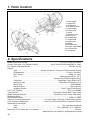
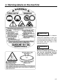
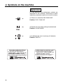
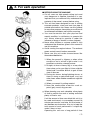
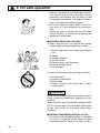
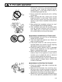
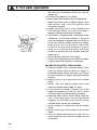
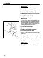
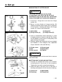
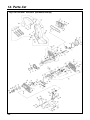
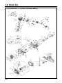
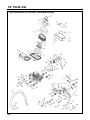
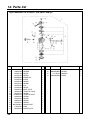
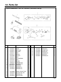
848-C8X-93A1 (60 ) OWNER / OPERATOR MANUAL CUT-OFF SAW HC510DV Dust Collection Type WARNING Diamond wheel use only, Do not use abrasive wheels with this product. WARNING WARNING The engine exhaust from this product contains chemicals known to the State of California to cause cancer, birth defects or other reproductive harm. Before using our products, please read this manual carefully to understand the proper use of your unit. APPLICABLE SERIAL NUMBERS : 200101 and up SAFETY FIRST Instructions contained in warnings within this manual marked with a symbol concern critical points which must be taken into consideration to prevent possible serious bodily injury, and for this reason you are requested to read all such instructions carefully and follow them without fail. ■ WARNINGS IN THE MANUAL WARNING This mark indicates instructions which must be followed in order to prevent accidents which could lead to serious bodily injury or death. IMPORTANT This mark indicates instructions which must be followed, or it leads to mechanical failure, breakdown, or damage. NOTE This mark indicates hints or directions useful in the use of the product. 1. 2. 3. 4. 5. 6. 7. 8. 9. 10. 11. 12. CONTENTS Parts location …………………………………4 Specifications …………………………………4 Warning labels on the machine ……………5 Symbols on the machine ……………………6 For safe operation ……………………………7 Set up …………………………………………12 Fuel……………………………………………14 Operation ……………………………………16 Maintenance …………………………………20 Storage ………………………………………31 Troubleshooting guide ………………………32 Parts list ………………………………………33 1. Parts location 1. 2. 3. 4. 5. 6. 7. 8. 9. 10. 11. 12. 13. 14. 15. 16. 17. Rear handle Safety lock Choke knob Air Cleaner cover Front handle Pulley cover Stand Decomp valve Drive case Throttle lever Cutter blade Blade cover Muffler Starter knobs Engine stop switch Fuel tank cap Flange bolt 2. Specifications Model Name and Number ···································································CUT-OFF SAW, HC510DV Overall Size (with 14 in. Blade)(LxWxH) ························· 29.4(735)x9.4(235)x19.8(495) in. (mm) Dry Weight (excluding Blade) ··············································································· 29.0 lbs (13 kg) Engine Type ··············································· Single-Cylinder Air-Cooled 2-Cycle Gasoline Engine Displacement ······················································································ 3.1cu-in. (49.3cm3) Max. Speed ···························································································· 12500 1/min (rpm) Fuel ······················································································· Mixture(Gasoline 50 : Oil 1) (when using ZENOAH genuine oil) Carburetor ········································································· Diaphragm Type (Walbro WT) Ignition System ······································································Electronic Controlled (C.D.I) Spark Plug·····································································································NGK BPM8Y Starter System······························································································Recoil Starter Stopping System ······································································ Earth Type (Push Button) Fuel Tank Capacity·····························································································18.5 fl.oz (0.55 ) Transmission········································································ Centrifugal Clutch, Belt Pulley, Gear Blade Rotating Direction························································ Clockwise (From Clutch Side View) Reduction Ratio ······················································································································ 4 : 1 Max Spindle Speed ······························································································ 3100 1/min (rpm) Vibration Isolation Mechanism····························· 8 Point Support Vibration Free Handle System Dust Collection Mechanism································Turbo Fan Drive Forced Dust Collection System Applicable Cutter Blade Type ·····························································································Dry type diamond blade Size ··················································································12 in. (305mm), 14 in. (355mm) Maximum Cut in Depth (by 14 in. Blade) ··········································································135 mm Specifications are subject to change without notice. 4 3. Warning labels on the machine IMPORTANT If warning label peel off or become soiled and impossible to read, you should contact the dealer from which you purchased the product to order new labels and affix them in the required location(s). WARNING Never modify your machine. We won't warrant the machine, if you use the remodeled machine or you don't observe the proper usage written in the manual. 5 4. Symbols on the machine WARNING For safe operation and maintenance, symbols are indicated on the machine. According to these indications, please be careful not to take a mistake. (a) (a) The port to refuel the "MIX GASOLINE" Position: FUEL TANK CAP (b) (b) Choke will close when pulling the choke knob Position: CHOKE KNOB (c) (c) It indicates the start (I) and stop (O) direction Position: SWITCH IMPORTANT ENGINE INFORMATION THIS ENGINE CONFORMS TO U.S. EPA PH1 FOR SMALL OFF-ROAD ENGINES. ENGINE FAMILY : 3KZXS. 0494LM ; EM ENGINE DISPLACEMENT : 49.3cm3 REFER TO OWNER’S MANUMAL FOR MAINTENANCE SPECIFICATIONS AND ADJUSTMENTS. MANUFACTURED: RedMax 6 Made in Japan INFORMATION IMPORTANTE CONCERNANT LE MOTEUR Ce moteur conformc aux normcs U.S. EPA PH1 pour les petits moteurs tout-terrain. Type de moteur : 3KZXS. 0494LM ; EM Cylindrée du moteur : 49.3cm3 Se référer au Manuel de l'utilisateur pour les spécifications d'entretien et les réglages. Manufacturé : RedMax Made in Japan 5. For safe operation ■ BEFORE USING THE MACHINE a. Cut-off saws are high-speed cutting tools and very dangerous to operate; therefore it is very important that you read and fully understand the contents of the owner’s manual before using. b. This unit has been designed for use in cutting concrete products, stone and cast-iron pipe at outside construction site. Never use this product for any other purpose since doing so could result in unforeseen accidents and injuries occurring. c. You must be certain that your physical and mental condition is satisfactory to operate this unit. Never attempt to operate it under the influence of drugs or alcohol, or when fatigued. d. Never allow children or anyone unable to fully understand the directions given in this manual to use this machine. e. Avoid running the engine indoors. The exhaust gases contain harmful carbon monoxide. f. Never use this unit under circumstances like those described below: 1. When the ground is slippery or when other conditions exist which might make it not possible to maintain a steady posture. 2. At night, at times of heavy fog, or at any other times when you’re your field of vision might be limited and it would be difficult to gain a clear view of the area. 3. During rain storms, during lightning storms, at times of strong or gale-force winds, or at any other times when weather conditions might be unsafe. 4. When you cannot fix cutting material. 5. Near the combustible materials such as: petrol (gas), wood, dry grass etc. g. When planning your work schedule, allow plenty of time to perform the work of cutting and allow plenty of time for rest. Limit the amount of time over which this unit is to be used continuously to somewhere around 10 minutes per session, and take 10~20 minutes of rest between work sessions. Also try to keep the total amount of work performed in a single day under 2 hours or less. Operating this unit over a long period of time 7 5. For safe operation exposes the operator to Whitefinger disease. This condition produces numerous burning sensations and interferes with the ability to feel and regulate temperature. Get medical advise at once if you experience these symptoms. h. Be sure to keep this manual handy so that you may refer to it later whenever any questions arise. i. Always be sure to include this manual when selling, lending, or otherwise transferring the ownership of this product. ■ WORKING GEAR AND CLOTHING a. When using this unit, you should wear proper clothing and protective equipment as follows; 1) Sturdy long pants and sturdy long-sleeved shirt 2) Helmet 3) Anti-dust goggles 4) Anti-dust musk 5) Vibration-proof, non-slip gloves 6) Steel-toed safety boots 7) Ear protectors b. And you should carry with you things as follows. 1) Attached tools 2) Properly reserved fuel 3) Spare wheel 4) Things to notify your working area ( Rope, warning signs ) WARNING Never cut any material containing asbestos without using a respirator specifically approved for that purpose. Some materials throw off dangerous sparks when cut. You should wear non-flammable clothing and gloves free of fuel, oil, or grease under these conditions. ■ WARNING CONSIDERING HANDLING OF FUEL 1. The engine of the RedMax product is designed to run on a mixed fuel which contains highly flammable gasoline. Never store cans of fuel or 8 5. For safe operation refill the tank of the unit in any place where there is a boiler, stove, wood fire, electrical sparks, welding sparks, or any other source of heat or fire which might ignite the fuel. 2. Never smoke while operating the unit or refilling its fuel tank. 3. When refilling the tank, always turn off the engine and allow it to cool down. Take a careful look around to make sure that there are no sparks or open flames anywhere nearby before refueling. 4. Wipe spilled fuel completely using a dry rag if any fuel spillage occurs during refueling. 5. After refueling, screw the fuel cap back tightly onto the fuel tank and then carry the unit to a spot 10feet (3m) or more away from where it was refueled before turning on the engine. ■ WARNING CONSIDERING CUTTING BLADE a. Diamond wheel use only. Do not use abrasive wheels with this product. b. Treat the wheel with special care. Never roll, drop or bump the wheel. c. Use proper wheel for the cutting material. Improper wheels may shatter or break, exposing the operator to serious injury or death. d. Check the wheel for broken, loose, or damaged parts before attaching it to the engine unit. Repair or replace before using. e. When replacing the blade, run the engine without load in low speed for more than 3 minutes so as to check the unit for abnormal noise or vibration before the actual cut. f. Never do the zigzag cut, curve cut, diagonal cut (without guide) or chape. Never use the side surface of the wheel. ■ WARNING ON STARTING THE ENGINE a. Check the condition and safety of working area and cutting object. b. Remove any obstacle from working area. Warning signs should be placed around the hazardous area (within a perimeter of 50 feet of the operator) into which no one should enter. c. When work is to be performed simultaneously by two or more persons, preconcert how to check 9 5. For safe operation the other one’s presence and how to sign the danger etc. d. Fix the cutting object if it is unfixed. e. Never operate the engine without wheel guard. f. Adjust the wheel guard to deflect sparks, dust, and material away from the operator and flammable materials. g. Inspect the entire unit for loose fasteners and fuel leakage. Make sure that the blade is properly installed and securely fastened. h. The product is equipped with a centrifugal clutch mechanism, so the wheel begins to rotate as soon as the engine is started when the throttle is in the start position. When starting the engine, place the unit on firm ground or other solid surface in an open area and hold it firmly in place so as to ensure that neither the wheel comes into contact with any obstacle when the engine starts. i. Never attempt to drop-start the engine. j. Be sure the wheel does not turn while the engine is idling. Adjust the carburetor if necessary. ■ OPERATION SAFETY PRECAUTIONS a. Grip the handles firmly with both hands. Place your feet slightly apart so that your weight is distributed evenly across both legs, and always be sure to maintain a steady, even posture while working. b. Keep all parts of your body away from rotating wheel. c. Never raise the engine speed above the maximum spindle speed (3000 1/min(rpm)). d. If the unit start to shake or vibrate, turn off the engine and check the whole unit. Do not use it until the trouble has been properly corrected. e. Keep the wheel always sharp. While using the unit, if the wheel won’t cut well caused by clogging, set the teeth of the saw by cutting concrete block, clayware or sandstone. f. Avoid standing in a direct line with the cutting wheel. g. Never force to push off the wheel on the cutting object. h. Use only downward pressure on the saw, as lateral pressure may cause the blade to brake and shatter. 10 5. For safe operation i. Do not cut above shoulder height. j. If someone calls out while working or if you wish to continue work in another spot, or if you want to check the unit, always be sure to turn off the engine before making your next move. k. Never touch the spark plug or plug cord while the engine is in operation. Doing so may result in being subjected to an electrical shock. l. Never touch the muffler, spark plug, or other metallic parts of the engine while the engine is in operation or immediately after shutting down the engine. Doing so may result in serious burns. ■ MAINTENANCE SAFETY PRECAUTION a. In order to maintain unit in proper working order, perform the maintenance and checking operations described in this manual at regular intervals. b. In the event that any parts must be replaced or any maintenance or repair work not described in this manual must be performed, please contact a representative from the store nearest RedMax authorized servicing dealer for assistance. c. Under no circumstances should you ever take apart the product or alter it in any way. d. When replacing any parts or when replacing the oil or any lubricants, always be sure to use only RedMax products or products which have been certified by RedMax. e. On checking or servicing, be sure to wear thick, sturdy gloves and use only proper tools and equipment, shut off the engine and remove the spark plug wire to prevent injury. ■ AFTER USING THE SAW a. Remove the cutting wheel when transporting the unit. b. Store the unit, with cutting wheel removed, safely away from children. 11 6. Set up WARNING Use adequate cutter blades suited to materials to be cut. Use of inadequate cutter blades may cause irregular wear of blades, poor cutting performances, or irregular overheating, etc. Continuance of those inadequate operations may damage the blades and cause serious accidents. ■ CHANGE OF DUST STOPPER IMPORTANT SE1 • To apply 12 inch blades, the dust stopper L (on the engine starter side) shall be exchanged with an attached 12 inch version before fitting blades. • In case the dust stopper is unchanged, dust collection performances become poor. (1) 14 inch version dust stopper (2) Screw (3) Mounting bracket (a) Remove 14 inch version dust stopper (b) Fix 12 inch version dust stopper 1. Remove a dust stopper fixed left inside of the blade cover. 2. Remove a stopper element from a dust stopper mounting bracket. Properly fix an attached 12 inch version stopper element on the mounting bracket. 3. Reassemble the dust stopper to the blade cover as original. NOTE Securely keep the removed dust stopper element as it is required for 14 inch blade operations. 12 6. Set up ■ MOUNTING OF CUTTER BLADE WARNING SE2 The flange bolt shall be securely fixed. (Fixing torque: 266~434 in-lbs (30~50 N·m)) Insufficient fixing of the bolt may cause brake away of the blade and is extremely dangerous. 1. Unscrew a flange bolt and remove flange washer (A). 2. Mount a cutter blade on flange washer (B) aligning its centre hole correctly with a projection of the washer. Holding the blade with flange washer (A), screw in the flange bolt. SE3 (1) Cutter blade (3) Flange washer (A) (2) Flange bolt (4) Flange washer (B) 3. Insert an attached bar (6mm diameter) to a hole on pulley cover as shown in the left Fig. Slowly turn the blade to find a hole on a belt pulley, and apply locking of the pulley. 4. Securely tighten the flange bolt with an attached eye wrench of 17mm diagonal size. (Specified torque: 266~434 in-lbs (30~50 N·m)) (1) Pulley cover (3) Bar (5) Eye wrench (2) Cutter blade (4) Flange bolt (6) Tighten IMPORTANT These attached tools must be used also to remove the cutter blade. SE4 ■ FITTING DUST HOSE AND DUST BAG 1. Connect an attached dust hose on an exhaust outlet behind a fan cover of the machine. Tighten the hose with a metal band securely. 2. Insert the end of the dust hose to the inlet of dust bag and securely fix with a cord on the bag. (1) Dust hose (3) Dust bag (2) Metal band (4) Tying Cord 13 7. Fuel WARNING • Gasoline is very flammable. Avoid smoking or bringing any flame or sparks near fuel. Make sure to stop the engine and allow it cool before refueling the unit. Select outdoor bare ground for fueling and move at least 3m (10ft) away from the fueling point before starting the engine. • The RedMax engines are lubricated by oil specially formulated for air-cooled 2-cycle gasoline engine use. If RedMax oil is not available, use an anti-oxidant added quality oil expressly labeled for air-cooled 2-cycle engine use. (JASO FC GRADE OIL or ISO EGC GRADE) • Do not use BIA or TCW (2-stroke watercooling type) mixed oil. ■ RECOMMENDED MIXING RATIO GASOLINE 50:OIL 1 (when using ZENOAH genuine oil) 50:1 MIXING CHART GASOLINE gal. 1 2 3 4 5 2-CYCLE OIL fl.oz 2.6 5.2 7.8 10.4 13 GASOLINE liter 2-CYCLE OIL ml 1 20 2 40 3 60 4 80 5 100 • Exhaust emission are controlled by the fundamental engine parameters and components(eq., carburation, ignition timing and port timing) without addition of any major hardware or the introduction of an inert material during combustion. • These engines are certified to operate on unleaded gasoline. • Make sure to use gasoline with a minimum octane number of 89 RON (USA/Canada: 87AL) • If you use a gasoline of a lower octane value than prescribed, there is a danger that the engine temperature may rise and an engine problem such as piston seizing may consequently occur. • Unleaded gasoline is recommended to reduce the contamination of the air for the sake of your health and the environment. • Poor quality gasolines or oils may damage sealing rings, fuel lines or fuel tank of the engine. ■ HOW TO MIX FUEL IMPORTANT Pay attention to agitation. 1. Measure out the quantities of gasoline and oil to be mixed. 2. Put some of the gasoline into a clean, approved fuel container. 3. Pour in all of the oil and agitate well. 4. Pour In the rest of gasoline and agitate 14 7. Fuel again for at least one minute. As some oils may be difficult to agitate depending on oil ingredients, sufficient agitation is necessary for the engine to last long. Be careful that, if the agitation is insufficient, there is an increased danger of early piston seizing due to abnormally lean mixture. 5. Put a clear indication on the outside of the container to avoid mixing up with gasoline or other containers. 6. Indicate the contents on outside of container for easy identification. ■ FUELING THE UNIT 1. Untwist and remove the fuel cap. Rest the cap on a dustless place. 2. Put fuel into the fuel tank to 80% of the full capacity. 3. Fasten the fuel cap securely and wipe up any fuel spillage around the unit. long period of time, clean the fuel tank after rendering it empty. Next, activate the engine and empty the carburetor of the composite fuel. 6. In the case of scrapping the used mixed oil container, scrap it only at an authorized repository site. NOTE As lot details of quality assurance, read the description in the section Limited Warranty carefully. Moreover, normal wear and change in product with no functional influence are not covered by the warranty. Also, be careful that, if the usage in the instruction manual is not observed as to fhe mixed gasoline, etc. described therein, if may not be covered by the warranty. WARNING 1. Select bare ground for fueling. 2. Move at least 10feet (3meters) away from the fueling point before starting the engine. 3. Stop the engine before refueling the unit. At that time, be sure to sufficiently agitate the mixed gasoline in the container. FOR YOUR ENGINE LIFE, AVOID; 1. FUEL WITH NO OIL(RAW GASOLINE) – It will cause severe damage to the internal engine parts very quickly. 2. GASOHOL – It can cause deterioration of rubber and/or plastic parts and disruption of engine lubrication. 3. OIL FOR 4-CYCLE ENGINE USE – It can cause spark plug fouling, exhaust port blocking, or piston ring sticking. 4. Mixed fuels which have been left unused for a period of one month or more may clog the carburetor and result in the engine failing to operate properly. 5. In the case of storing the product for a 15 8. Operation ■ STARTING ENGINE WARNING • Before starting the engine, check if there is any problem such as loose fitting of cutter blade or fuel leakages. • Place the machine on the ground and hold securely when starting. Do not start the engine while hanging it by one hand because the cutter blade may contact with the ground or other obstacles. • As the engine starts with throttle lever locked in a starting position, the cutter blade starts to turn at the same time. Avoid the cutter blade from contacting the ground and keep surrounding obstacles away. • Confirm if the cutter blade stops to turn when the throttle lever is fully retarded. In case the blade continues to turn, stop the operation and adjust or maintain to the proper operation. • To avoid accidents, do not lock the throttle lever during operation. • Be sure to hold the handle by both hands during operation. Left hand shall always hold a front handle with the thumb downward. OP1 IMPORTANT Continuous high speed idling will apply extra load to the engine. Release the throttle lever when cutting operation is not continued. Especially during a running-in period, avoid high speed idling as the engine is exposed to a heavy load. 1. Apply fuel in a tank and secure a cap. (OP1) (1) Fuel inlet (2) Fuel tank cap OP2 2. Power switch to ON position. 3. Pull a choke knob on rear right side of the machine for choke closing. (OP2) (1) Switch (3) OPEN 16 (2) Choke knob (4) CLOSE 8. Operation NOTE In case of restarting immediately after stopping the engine, pull the starter knob with the choke knob pushed in (choke open). OP3 4. Push in a decomp valve on right side of the machine. (OP3) (1) Decomp valve NOTE In case a starter rope felt to be heavy, check if the decomp valve is pushed in. OP4 5. Place the machine on stable ground and confirm that there is no obstacle around the cutter blade. As in the left Fig., securely hold the machine with left hand and right foot, and pull the starter knob. Pull the knob lightly in the beginning and then hard when it becomes heavy. (OP4) IMPORTANT Do not fully pull out the rope at once or let the knob go for free return as those may cause failure of the starter. 6. When initial combustion noise is heard, pull the throttle lever slightly to return the choke knob to the first stage position, press the decomp valve, and pull the starter knob again. IMPORTANT By pulling the starter rope repeatedly with choke knob pulled out position, the engine may have difficulty to start due to excess fuel. In case the engine does not start though the rope is repeatedly pulled, push in the choke knob and pull the rope until it starts. Otherwise, remove a spark plug to dry its electrode, and reassemble. Try again the starting operation. 7. When the engine is started, lightly pull the throttle lever and unlock the start setting button. 17 8. Operation In case of cold start of the engine, apply 1~2 minutes of warming up operation before use. ■ STOPPING ENGINE WARNING OP5 • In an emergency, immediately stop the engine. • Even after stopping the engine, the cutter blade continues to turn awhile by inertia. Do not touch the blade until it is fully stopped. • Do not touch a muffler or the spark plug by bare hands immediately after stopping the engine. There is a danger of burn for its high temperature. 1. Return the throttle lever and operate for a while at low speed. 2. OFF the power switch. (1) ON (3) Switch (2) OFF IMPORTANT Stopping operation at high engine speed causes extra stress on the engine. Except for emergency, reduce the engine speed by returning the throttle lever, and then apply stop operations. 18 8. Operation OP6 ■ CUTTING OPERATION • For cutting, hold the machine in your body centre and lead the dust hose through both legs. Lightly bend the knees and keep a stable posture. • When applying the cutter blade to a work, start with low speed to form a guide notch, and then cut with full throttle. IMPORTANT Do not forcedly press the cutter blade during cutting. It may end up with quick wear of blade or troubles on a drive mechanism. OP7 ■ FOR AN EFFICIENT CUTTING OPERATION • In case the front guide tip is not contacting a work, capture of dusts becomes insufficient and its dust collection performance is spoiled. • A front guide under the blade cover can slide. For cutting operation, press the front guide tip onto a work. • Dusts are sucked from the front guide tip and collected in a dust bag after passing through inside of the blade cover, a dust collection fan and the dust hose. • The dust collection performance is dependable to cutting direction. Before stating the operation, refer (OP7) and decide a cutting direction so that dusts are efficiently collected thorough the front guide • Dust collection performance is spoiled if the dust bag is full with dusts or clogged with water. • At least once in every day, remove the dusts in the dust bag by opening the fastener. In case the bag is wet with water, dry it thoroughly for next use. (1) Front guide (A) Horizontal Cutting Move cutter back from forward. (B) Vertical Cutting Move cutter downward. 19 9. Maintenance Maintenance, replacement, or repair of the emission control device and systems may be performed by any non-road engine repair establishment or individual. WARNING • Be sure to stop the engine for check and maintenance. • Do not modify the machine nor disassemble the engine. • Use RedMax genuine or specified spare parts and oils. ■ AIR CLEANER The air cleaner is adhered with much dusts produced by a cutting operation. At the end of day’s operation, be sure to check and clean it as follows: 1. Remove 2 screws above the air cleaner cover and remove the cover. 2. Remove 2 screws above a top plate and remove the plate. 3. Remove a main filter together with a felt filter. 4. Remove the felt filter from the main filter. 5. Remove adhered dusts on the main filter by tapping the edge of the filter on a hard plane, for example. MA1 IMPORTANT • The main and felt filters are of dry type. Do not wet with water nor apply oils. Those will degrade the performance. • Do not apply high pressure air blows or a wire brush to clean the main filter. These will quicken clogging or damaging of the filter. 6. Dusts adhered on the felt filter are removed by gently needing it. For heavy contamination, wash in warm detergent water and dry thoroughly. Then reassemble to the main filter as original. (1) Air cleaner cover (3) Felt filter 20 (2) Top plate (4) Main filter 9. Maintenance IMPORTANT • Clogging of air filter reduces engine performances. Inside of an engine will quickly wear by dusts if an air cleaner cover is not correctly fitted or if a filter is missed, deformed, or damaged. • Avoid dusts to penetrate into the engine when removing the air filter. Cover an air inlet with a cloth after removing the filter. • To keep the engine performance, change the air filter at every 20 hours of operation. ■ SPARK PLUG WARNING MA2 0.6~0.7mm Do not touch the spark plug by bare hands immediately after stopping the engine. There is a danger of burn for its high temperature. About every 25 hours of operation, remove the spark plug and clean contaminant on electrodes with a wire brush, etc. Applicable gap between the electrodes is 0.6~0.7mm. Use specified spark plug for exchange. Specified Spark Plug: NGK BPM8Y IMPORTANT Electrodes of the spark plug are contaminated by over sucking of fuel or by poor quality oil. This may cause the engine start difficult. MA3 ■ FUEL FILTER About every 25 hours of operation, remove a fuel filter from the fuel tank and remove adhered debris. In case the filter is clogged, exchange with a new one. Care should be taken not to bend a fuel pipe when setting the filter back into the tank. (1) Fuel filter 21 9. Maintenance IMPORTANT In case the fuel filter is clogged or the fuel pipe is bent, engine speed may not increase or may become unstable. ■ COOLING AIR PASSAGE WARNING MA4 • Do not touch the cylinder, muffler or spark plug by bare hands immediately after stopping the engine. There is a danger of burn for its high temperature. • On the starting inspection, check the muffler and clean if there are adhered wood chips or dry leaves. Those may cause overheating of the muffler. Also to avoid fire, keep clean the muffler area. This engine is an air cooling type. If cooling air inlet or cylinder fins are choked with debris, the engine may overheat and cause troubles. Check and remove debris from time to time. (MA4) (1) Air Inlet (2) Cylinder fin IMPORTANT • When the spark plug or air filter is removed for cleaning, cover the fixing hole or the air inlet with cloth to avoid dusts. • The covers shall be reassembled correctly as original. Failure in assembling may result in irregular wear or damage of components by machine vibrations. MA5 ■ BLADE DRIVE BELT On the starting inspection, check tension and wear status of a blade drive belt. Adjust or exchange it if necessary. Belt Tension The belt is normal if it sags about 5mm by pushing the belt outward with a finger. (MA5) (1) Blade drive belt 22 9. Maintenance MA6 This machine is equipped with a spring loaded semi-automatic tensioner. Therefore, by slackening cutting head fixing nuts and bolts, correct tension is always maintained. (MA6) Apply following procedures if readjustment is required: (1) Cutting head (2) Spring (3) Drive case MA7 1. Slacken 3 pieces of flange nuts which are holding the cutting head. (MA7) (1) Slacken MA8 2. Slacken a bracket bolt on the starter side. (MA8) (1) Slacken 3. By up and down the cutting head several times, belt tension is regulated automatically by a spring force. 4. Tighten those slacken bolt and nuts as original. ■ BELT EXCHANGE As the belt wears out, correct tension cannot be maintained just by its adjustment. In such a case, ask your sales dealer to exchange, or purchase new belt and exchange in following procedure: IMPORTANT MA9 The belt for exchange shall be a genuine part (Part No. 2884-61510). DISASSEMBLING PROCEDURE 1. Slacken 2 screws and remove a pulley cover. 2. By plug wrench, slacken 3 nuts which are holding the cutting head. (MA9) (1) Cutting head (2) Pulley cover 23 9. Maintenance MA10 3. Slacken a stay bolt on opposite side and remove together with a washer. (MA10) (1) Stay (2) Washer (3) Bolt MA11 4. Slacken a semi-auto tensioner bolt using angle wrench. Push the cutting head toward the engine while swinging it up and down to slacken the belt tension. (MA11) (1) Push toward the engine (2) Bolt (3) Slacken MA12 5. Remove the belt out from groove of pulley on the cutting head. 6. Remove a belt cover on the drive case. 7. Slacken and remove 4 screws and 2 nuts which are fixing the drive case on the main body. (MA12) (1) Drive case (3) Pulley MA13 (2) Drive belt (4) Belt cover 8. As removing the drive case and cutting head together from the main body, remove the belt out from a pulley on the main body. 9. Slacken 3 nuts which are fixing the cutting head, then separate the drive case and the cutting head. Remove the belt. At this time, a belt tensioner spring and a boss built into the cutting head come out together. (MA13) (1) Clutch drum (3) Cutting head (5) Boss (2) Drive case (4) Spring ASSEMBLING PROCEDURE 1. Lay the belt inside the drive case temporarily. Temporarily fix the cutting head with built-in belt tensioner spring and a guide to the drive case using 3 nuts. 24 9. Maintenance 2. Put the belt into a pulley groove on the main body. Then engage fan drive spline axle of the drive case with splines on the main body. 3. Assemble the drive case to the main body with 2 nuts and 4 screws. 4. Put the belt into the cutting head pulley. 5. Apply tension on the belt by screwing in the belt tensioner bolt to the end of the case. 6. Tighten 3 nuts and fix stay bolt on the opposite side as original. 7. Fit the belt cover and the pulley cover as original. 8. Finally, turn the cutter blade 1~2 times by hand and check belt tension by pushing it with a finger from backside of the drive case. ■ FAN DRIVE BELT BELT TENSION ADJUSTMENT AND EXCHANGE The belt is normal if it sags about 5mm by pushing the belt outward with a finger. Apply following procedures if readjustment is required: MA14 1. Slacken 5 screws on the belt cover and remove the belt cover. 2. Slacken centre bolt of an idler pulley. 3. Apply plug wrench to a hex nut on belt adjustment plate and turn left (counter clockwise) to increase tension or right (clockwise) to decrease tension. (MA14) (1) Idler pulley (3) Belt (5) Tighten (2) Belt adjustment plate (4) Bolt (6) Slacken NOTE To exchange the belt, fully loosen the belt by turning the belt adjustment plate right to the end and take it off. IMPORTANT The belt for exchange shall be a genuine part (Part No. 2894-64710). 25 9. Maintenance 4. Tighten the centre bolt of the idler pulley to fix the belt adjustment plate. 5. Fit the belt cover as original. ■ ENGINE ADJUSTMENT (MA15) WARNING It is dangerous if the cutter blade continues to turn even fingers are removed from the throttle lever. In case it is not solved by readjusting an idle adjust screw with following procedure, there are possibility of throttle lever failure or clutch failure. Ask sales dealer for check and repair. The carburetor on your unit has been factory adjusted, but may require fine tuning due to change in operating conditions. Before adjusting the carburetor, make sure that provided are clean air/fuel filters and fresh, properly mixed fuel. When adjusting, take the following steps: NOTE Be sure to adjust the carburetor with the cutter blade attached. MA15 1. H and L needles are restricted within the number of turn as shown below. H needle: L needle: 0 ~ -1/4 0 ~ -1/4 2. Start engine and allow it to warm up in low speed for a few minutes. 3. Turn idle adjusting screw (T) counter-clockwise so that saw chain does not turn. If idling speed is too slow, turn the screw clockwise. 26 9. Maintenance 4. Make a test cut adjust the H needle for best cutting power, not for maximum speed. Standard Idle Speed: 2300~2700 rpm. (1) Idle adjust screw (T) (2) Low speed needle (L) (3) High speed needle (H) 27 9. Maintenance ■ STARTER ROPE EXCHANGE WARNING When exchanging the starter rope, pay attention so that built-in recoil spring does not jump out. Mistake in operation may end up with injury to the eye, etc. by jumped out spring. The starter rope wears and deteriorates with usage. In case the rope becomes shaggy or partially worn, suggest exchanging it soon to avoid rope cut on operation site. To exchange rope, ask sales dealer or obtain RedMax genuine part and go through following procedure: MA16 1. Remove a recoil case from the machine. (MA16) (1) Recoil case MA17 2. Pull out the starter rope and make a temporary knot in the middle. Pull out the rope from the starter knob and unknot its end knot. (MA17) (1) Starter rope (2) Temporary knot (3) Starter knob (4) Washer MA18 3. Unknot the temporary knot and slowly retract the rope. 4. After removing a reel fixing screw, take out a reel, spacer and washer from the recoil case while holding a recoil spring by left hand. (MA18) (1) Recoil spring (2) Reel (3) Spacer 28 9. Maintenance NOTE In case irregular wear is observed on a recoil boss or reel bore, exchange for new components. MA19 5. Remove the rope from the reel. 6. Make a knot in end of new rope and lead it through a reel hole from outside. Pull the rope hard to engage the knot into a reel pit and put end of the knot into a reel notch. (MA19) (1) Notch IMPORTANT In case the rope knot is too large or the rope end is protruded from the reel, the rope retraction may become difficult. MA20 MA21 7. After leading the rope through a guide of recoil case, align a notch in the back of reel with end of the coil spring. Assemble a spacer and the reel to the recoil boss. By turning the reel left and right, engage the reel notch with the spring end. 8. Put a washer on the recoil boss and fix the screw as original. 9. Lead the rope through a guide hole on the starter case, starter knob and a washer and make a knot (double overhand knot). (MA20) 10.Pull out the rope from a notch in the reel rim and turn the reel 4~5 turns clockwise. (MA21) (1) Notch 11.Holding the reel with left hand, pull out the rope with right hand. Ease the left hand and let the 29 9. Maintenance rope slowly be retracted to the reel. 12.Pull the rope 2~3 times to confirm if it is fully retracted. If it is not fully retracted, pull it out halfway and while holding the reel with left hand, hitch the rope to the reel notch and turn additional 2~3 turns clockwise. IMPORTANT Excessive turns of reel cause overload on the coil spring and may break it in short time. As a guideline, retraction of the recoil spring is that the reel can be turned 1~2 turns further with the rope completely drawn out. 13.Reassemble the recoil case to the main body as original. 30 10. Storage WARNING When discharging fuel, be careful not to spill fuel and completely wipe off if spilled. Also, securely close a cap of storage tank. IMPORTANT • In case the machine is left for long time, inside of the carburetor may be clogged and cause engine failure (starting failure or poor output power). • During storage, make fuel tank cap loose. If it is tighten too much, cap packing may deform by temporal change. 1. Remove the dust hose and the dust bag from the body. 2. Open the dust bag fastener and remove internal dusts completely. 3. Remove debris and dirt on the machine body. 4. After discharging fuel from the fuel tank, start the engine and run until it stops. 5. Remove the spark plug and drop 1~2 cc of 2 cycle engine oil into the plug hole, then pull the starter rope for 2~3 times. After fitting the spark plug as original, pull the starter rope and stop at compression position. 6. Fully slack the tension of pulley drive belt. 7. Fully slack the tension of fan drive belt. 8. Dismount the cutter blade. 9. After applying appropriate cover on the machine, store it in an adequate place such as storage shelf, keeping moisture, dusts and children away. 31 11. Troubleshooting guide Case 1. Starting failure CHECK fuel tank fuel filter carburetor adjustment screw sparking (no spark) spark plug ➞ ➞ ➞ ➞ ➞ ➞ PROBABLE CAUSES incorrect fuel fuel filter is clogged out of normal range spark plug is fouled/wet plug gap is incorrect disconnected ➞ ➞ ➞ ➞ ➞ ➞ ACTION drain it and with correct fuel clean adjust to normal range clean/dry correct (GAP: 0.6~0.7mm) retighten Case 2. Engine starts but does not keep running/Hard re-starting. CHECK fuel tank carburetor adjustment screw muffler,cylinder (exhaust port) air cleaner cylinder fin, fan cover ➞ ➞ ➞ ➞ ➞ PROBABLE CAUSES incorrect fuel or staled fuel out of normal range carbon is built-up clogged with dust clogged with dust ➞ ➞ ➞ ➞ ➞ ACTION drain it and with correct fuel adjust to normal range wipe away wash clean When your unit seems to need further service, please consult with our RedMax service shop in your area. 32 12. Parts list CUT-OFF SAW HC510DV NOTE : 1. Use KOMATSU ZENOAH genuine parts as specified in the parts list for repair and/or replacement. 2. KOMATSU ZENOAH does not warrant the machines, which have been damaged by the use of any parts other than those specified by the company. 3. When placing parts orders for repair and/or replacement, check if the model name and the serial number are applicable to those specified in the parts list, then use parts number described in the parts list. 4. The contents described in the parts list may change due to improvement. 5. The parts for the machine shall be supplied seven (7) years after the machine is discontinued. [It is possible that some specific parts may be subject to change of their delivery term and list price within the limit of seven (7) years after the machine is discontinued. It is also possible that some parts may be available even after the limit of seven (7) years.] Aug. 2006 APPLICABLE SERIAL NUMBERS : 200101 and up 33 12. Parts list Fig.1 CUTTER UNIT HC510DV (S/N 200101 and up) 34 Fig.1 CUTTER UNIT HC510DV (S/N 200101 and up) Key# Part Number Description Q'ty 1 2 3 4 5 6 7 8 9 10 11 12 13 14 15 16 17 18 19 20 21 22 23 24 25 26 27 28 29 30 31 32 33 34 2894-61100 01252-60510 06004-06001 2670-21220 2894-64110 2894-64120 2894-64210 2894-64250 2894-64300 01643-30823 3350-43231 2894-64410 2894-64420 2894-64450 2670-14220 2894-64501 2894-64610 2894-64620 01643-30623 01252-60614 2894-64710 2894-64811 2670-14320 T2069-64850 2891-61730 2670-21320 2894-61180 3350-53410 2884-61310 2884-61320 2670-14130 3350-53410 01643-30823 2884-61510 CASE COMP • BOLT • BEARING • SEAL SHAFT, inlet PULLEY FAN SPACER SHAFT COMP WASHER NUT COVER, fan SEAL SCREEN SCREW M5x20 IDLER PULLEY COMP SHAFT, idler CAM PLATE WASHER BOLT BELT COVER BELT SCREW M5x14 LABEL LABEL SCREW M5x25 SCREW M5x55 NUT M8 COVER, pulley PLATE SCREW M5x10 NUT M8 WASHER V-BELT 1 1 4 1 1 1 1 1 1 1 1 1 1 1 6 1 1 1 1 1 1 1 5 1 1 1 2 2 1 1 2 3 1 1 51 52 53 54 55 56 57 58 59 60 61 62 63 64 65 66 67 68 69 70 71 72 2894-61610 2894-61620 2894-61640 2894-61650 3350-43231 2894-61710 2670-14320 2894-62100 0305-00512 2884-62310 2884-62320 06000-06001 06000-06002 06000-06201 04065-03212 2884-62380 0230-50825 2884-62410 2850-14220 2884-62430 2884-62450 07005-00812 SPRING GUIDE BOLT M8x60 GUIDE NUT NUT COVER, spring SCREW M5x14 GEARCASE COMP • PIN • SEAL • SEAL • BEARING • BEARING • BEARING • SNAPRING • STUD • STUD GASKET BOLT M5x20 SCREW M5x25 O-RING WASHER 1 1 1 1 1 1 3 1 2 1 1 3 2 1 1 2 1 1 4 4 1 1 Key# Part Number Description Q'ty 73 74 75 76 77 78 79 80 81 82 83 84 85 86 87 88 89 01010-80810 2884-62500 2884-62600 2884-62710 2884-62720 2884-62800 2885-63110 2884-63120 0290-20820 3350-43231 2884-65710 2894-65730 2670-25430 T2069-63210 2884-63220 T2069-63310 2884-63350 BOLT M8x10 SHAFT COMP GEAR COMP BEARING WASHER SHAFT COMP PULLEY SPACER WASHER NUT PLATE, end END RING SCREW M4x10 WASHER SPACER WASHER BOLT 1 1 1 1 2 1 1 1 1 1 1 1 3 1 1 1 1 101 102 103 104 105 106 107 108 109 110 111 112 113 114 115 116 117 118 119 120 121 122 123 124 125 126 127 128 129 130 131 132 133 134 T2069-65100 T2069-65110 01252-60510 2894-65210 2894-65220 2670-25430 3388-23110 T2069-65120 2670-14320 2670-14220 01252-60620 2894-66110 2894-66120 2894-66150 2894-66210 2894-66220 2894-66250 2670-14130 2894-66310 2894-66400 2894-66450 2894-66460 2894-66510 2894-66460 2894-66610 2894-66820 2894-66630 01252-60620 2894-66650 2894-66660 01252-60620 2894-66680 01252-60620 T2069-65150 COVER ASSY • BLADECOVER • BOLT • SEAL for 14" • PLATE • SCREW • GROMMET • COVER UPPER • SCREW • SCREW BOLT FRONT GUIDE (R) FRONT GUIDE (L) CUSHION JOINT BOLT NUT JOINT BOLT SCREW ROLLER SLIDE GUIDE COMP • ROLLER • SPRING PIN RETURN SPRING SPRING PIN RETURN SPRING NUT SPACER BOLT NUT WASHER BOLT STOPPER BOLT BOLT LABEL, caution 1 1 1 2 2 4 1 1 7 1 5 1 1 1 1 2 1 1 2 1 2 1 1 1 1 1 1 1 1 1 1 1 1 1 35 12. Parts list Fig.2 POWER UNIT (1) HC510DV (S/N 200101 and up) 36 Fig.2 POWER UNIT (1) HC510DV (S/N 200101 and up) Key# Part Number 1 2 3 4 5 6 7 8 9 10 11 12 13 14 15 16 17 18 19 20 21 22 23 24 25 26 27 28 29 30 31 32 33 34 35 36 37 38 39 40 41 42 43 44 45 46 47 48 2884-12110 2884-14100 3388-23110 2880-14111 2880-14120 2880-14150 2670-14311 2670-14320 2880-14350 2880-14361 2670-14211 2850-14220 2810-15220 2850-15230 2810-15113 2670-14130 3356-15210 2880-82310 2880-82350 2884-21000 3356-21130 T4012-21240 04065-03515 2670-21210 2670-21220 2884-21230 2670-21250 2810-22511 2810-22521 2670-21311 2670-21320 2810-22210 3310-82230 2810-22411 3388-23110 3330-23121 3350-26230 2884-23310 2880-41110 2880-41210 2880-41310 3350-41320 1400-41410 2670-41510 2884-42000 1000-43240 2894-21280 2670-25430 51 52 53 54 55 56 57 58 59 60 2670-71101 1850-75220 2670-71130 0308-00040 0290-20820 3350-43231 2880-71300 2810-71204 2810-71220 2670-71230 Description Q'ty CYLINDER VALVE ASS'Y GROMMET PIPE SPRING GUIDE BRACKET SCREW M5x14 SPACER GASKET GASKET, cylinder BOLT M5x20 BOLT NUT M5 MUFFLER SCREW M5x10 GASKET GUIDE (I) GUIDE (HL) CRANKCASE ASS'Y • SPRING PIN BEARING SNAP RING SEAL SEAL STUD ELBOW STOPPER STOPPER GASKET SCREW M5x25 PIPE CLIP MAT GROMMET VALVE CLIP GROMMET PISTON PISTON RING PISTON PIN SNAP RING BEARING WASHER CRANKSHAFT COMP KEY PLATE SCREW M5x10 1 1 1 1 1 1 1 2 1 1 1 4 2 2 1 1 1 1 1 1 3 2 1 1 1 2 1 1 1 1 4 1 1 1 1 1 1 1 1 2 1 2 1 2 1 1 1 2 ROTOR ASS'Y • RATCHET • SPRING • RING WASHER NUT COIL ASS'Y • COIL COMP • • CORD • • GROMMET 1 2 2 2 1 1 1 1 1 1 Key# Part Number Description Q'ty 61 62 63 64 65 66 67 2810-72110 1400-72121 2670-71320 2810-71250 2670-14220 2670-71510 T2069-71600 • CAP • SPRING • TUBE • GROMMET SCREW M5x20 CORD SWITCH ASS'Y 1 1 1 1 2 1 1 71 72 73 74 75 76 77 78 79 80 81 82 83 84 85 86 87 88 2670-14130 3699-90512 2810-21270 0260-30410 2884-75000 2810-75110 2810-75120 2810-75150 2670-75212 3317-75300 2884-75410 1400-75170 3310-75431 1400-86280 2670-14220 2880-75600 2670-14320 T2069-75130 SCREW SPARKPLUG NGK BPM8Y PLATE SCREW STARTER ASS'Y • CASE • GUIDE • BOSS • REEL • SPRING COMP • ROPE • KNOB • WASHER • WASHER • SCREW M5x20 FAN COVER COMP SCREW M5x14 LABEL 1 1 1 2 1 1 1 1 1 1 1 1 1 1 1 1 3 1 91 92 93 94 95 96 97 98 99 100 101 102 103 104 105 106 107 108 109 110 111 112 113 114 115 116 117 118 119 120 2616-51202 2616-51210 3350-51231 2894-51310 2884-51330 2894-51350 01240-00616 2894-51100 06004-06200 04065-03012 2884-82131 2884-82140 2884-82153 2810-82141 2880-82210 2880-82410 848-C80-82G0 2670-82430 2880-82511 2884-82520 2810-34303 2810-34312 2810-34350 3302-85400 2670-34401 2670-34430 2884-34500 2850-34501 3356-34310 2670-82421 CLUTCH ASS'Y • CLUTCH PLATE • SPRING COLLAR SPACER WASHER SCREW CLUTCH DRUM ASS'Y • BEARING • SNAPRING MANIFOLD O-RING SEAL SUPPORTER SCREW ROD, choke GROMMET GUIDE ROD, throttle GROMMET FUEL PIPE ASS'Y • PIPE • COLLER • FILTER ASS'Y TANK CAP ASS'Y • GASKET BREATER ASS'Y • BREATER • PIPE • GROMMET 1 1 1 1 1 1 1 1 1 1 1 1 1 1 2 1 1 1 1 1 1 1 1 1 1 1 1 1 1 1 37 12. Parts list Fig.3 POWER UNIT (2) HC510DV (S/N 200101 and up) 38 Fig.3 POWER UNIT (2) HC510DV (S/N 200101 and up) Key# Part Number 1 2 3 4 5 6 7 8 9 10 11 12 13 14 15 16 17 18 19 20 21 2884-31110 2670-14320 2884-82603 2884-82630 2884-82640 2670-14320 2884-83100 2884-83121 2884-83301 2884-83320 2880-32270 3310-31720 2884-83410 T1000-13170 2813-31210 T2069-85310 T2069-85320 2884-83610 2884-83620 2670-75520 T2062-31410 51 52 53 54 55 56 57 58 59 60 61 62 2884-31310 2884-31321 2670-14130 2670-14320 2894-32100 2671-32210 2884-32210 2670-14130 2884-32250 2670-21320 2810-33007 2810-33102 65 66 67 68 69 70 71 72 73 74 75 76 77 78 79 848-C80-33Y0 2810-33280 2670-75520 2810-33211 2670-33311 3356-33321 04025-00524 3356-33352 2670-34110 2671-32210 2880-35111 2670-35120 2810-35150 2880-35211 3350-35170 Description Q'ty Key# COVER, cylinder SCREW M5x14 PLATE COMP • SEAL • SEAL, plate SCREW M5x14 CLEANER COMP • ELEMENT PLATE ASS'Y • BRACKET • SCREW BOLT M5x14 COVER COMP • BOLT M5x18 LABEL LABEL LABEL HOLDER ELEMENT SCREW LABEL, EPA 1 5 1 1 1 4 1 1 1 1 1 2 1 1 1 1 1 1 1 3 1 DAMPER STAY SCREW M5x10 SCREW M5x14 LEFT HANDLE COMP SCREW TP5x19 STAY SCREW M5x10 SPACER SCREW M5x25 RIGHT HANDLE ASS'Y • HANDLE COMP 1 1 1 2 1 2 1 2 1 1 1 1 80 81 82 83 84 85 86 87 88 89 90 91 92 93 94 95 96 97 98 99 100 101 102 103 • PLUG • DAMPER • SCREW TP4x16 • GASKET • LEVER • SPRING • SPRING PIN ARM COVER SCREW TP5x19 DAMPER SCREW TP5x16 CAP DAMPER BOLT 1 1 1 1 1 1 1 1 1 1 4 4 4 2 2 Part Number 2880-35250 2894-53110 2894-53120 2670-55410 2894-53210 2894-53310 2670-14130 2894-53410 2671-32210 2894-53450 2670-35120 2894-53510 2884-53550 3310-53331 01252-60614 2894-53710 2671-32210 2894-54110 2894-54120 2894-54210 2670-14320 2670-21320 01643-30823 01010-80820 Description CAP BRACKET PLATE inner SCREW M4x14 DAMPER STAND SCREW M5x10 BRACKET SCREW TP5x19 STAND, end SCREW TP5x16 STAND SCREW M5x40 NUT BOLT M6x14 BRACKET, under SCREW TP5x19 BRACKET BOSS BOLT SCREW M5x14 SCREW M5x25 WASHER BOLT M8x20 Q'ty 2 1 1 2 1 1 3 1 2 1 2 1 2 2 1 1 2 1 1 1 1 2 1 1 39 12. Parts list Fig.4 CARBURETOR HC510DV (S/N 200101 and up) Key# Part Number 1 2 3 4 5 6 7 8 9 10 11 12 13 14 15 16 17 18 19 20 21 40 848-C8X-8101 3306-81380 2810-81120 3310-81130 T2050-06020 3310-81230 3310-81240 2841-81270 3310-81250 3310-81280 3356-81310 3356-81340 2670-81410 T2108-81370 2630-81460 2670-81430 2880-81470 3310-81351 848-C8A-80E1 1148-81390 2670-81450 Description Q'ty CARBURETOR ASS’Y (WT-648A) • SCREEN • COVER • SCREW • GASKET KIT • LEVER • SCREW • SPRING • PIN • COVER • INLET VALVE • THROTTLE VALVE • SPRING • THROTTLE SHAFT • SPRING • SCREW • SCREW • SCREW • CHOKE SHAFT • RING • CHOKE VALVE – 1 1 1 1 1 1 1 1 1 1 1 1 1 1 1 3 4 1 1 1 Key# Part Number 24 25 26 27 848-C80-81Z1 848-C80-80D0 1751-81190 848-C80-89D0 Description • LEVER • SPRING • WASHER • LEVER Q'ty 1 1 1 1 12. Parts list Fig.5 ACCESSORIES & TOOL SET HC510DV (S/N 200101 and up) Key# Part Number 1 2 3 4 5 6 7 8 9 10 11 12 13 14 15 16 17 2894-92310 2894-68310 2894-68210 2894-68110 3388-92110 6242-92110 2894-91000 3345-91110 3320-91140 3582-91330 2670-91150 3388-91310 0901-00810 09007-00528 09007-00632 2670-96310 2670-96320 31 32 33 34 2894-96000 2890-96100 2616-96210 2670-96220 Description Q'ty PLATE for 12" CLUMP DUST HOSE DUST BAG MASK GOGGLE TOOL SET • BAG • PLUG WRENCH • BAR • DRIVER • WRENCH 13x17 • SPANNER 8x10 • WRENCH 5 • WRENCH 6 • WRENCH T25 • WRENCH T20 1 1 1 1 1 1 1 1 1 1 1 1 1 1 1 1 1 SPACIAL TOOL SET (OP) • PULLER ASS'Y (OP) • WRENCH (OP) • STOPPER (OP) 1 1 1 1 Key# 35 36 37 38 39 40 41 Part Number 3350-96230 3350-96620 2670-96660 3350-96240 2670-96410 2810-96710 2894-96810 Description • GUIDE (OP) • GUIDE (OP) • HOLDER (OP) • GAUGE (OP) • WRENCH (OP) • GUIDE (OP) • WRENCH (OP) Q'ty 1 1 1 1 1 1 1 41 CALIFORNIA EMISSION CONTROL WARRANTY STATEMENT YOUR WARRANTY RIGHTS AND OBLIGATIONS The California Air Resources Board and KOMATSU ZENOAH are pleased to explain the emission control system warranty on your 2005 and later small off-road engine. In California, new small off-road engines must be designed, built and equipped to meet the state’s stringent anti-smog standards. KOMATSU ZENOAH must warrant the emission control system on your small off-road engine for the periods of time listed below provided there has been no abuse, neglect or improper maintenance of your small off-road engine. Your emission control system may include parts such as the carburetor and the ignition system. Where a warrantable condition exists, KOMATSU ZENOAH will repair your small off-road engine at no cost to you including diagnosis, parts and labor. Manufacturer’s warranty coverage: The 2005 and later small off-road engines are warranted for two years. If any emissionrelated part on your engine is defective, the part will be repaired or replaced by KOMATSU ZENOAH. Owner’s warranty responsibilities: – As the small off-road engine owner, you are responsible for the performance of the required maintenance listed in your owner’s manual. KOMATSU ZENOAH recommends that you retain all receipts covering maintenance on your small off-road engine, but KOMATSU ZENOAH can not deny warranty solely for the lack of receipts or for your failure to ensure the performance of all scheduled maintenance. – As the small off-road engine owner, you should be aware, however, that KOMATSU ZENOAH may deny you warranty coverage if your small off-road engine or a part has failed due to abuse, neglect, improper maintenance or unapproved modification. – You are responsible for presenting your small off-road engine to a KOMATSU ZENOAH distribution center as soon as a problem exists. The warranty repairs should be completed in e reasonable amount of time, not to exceed 30 days. If you have any questions regarding your warranty rights and responsibilities, you should contact KOMATSU ZENOAH AMERICA INC. at (770)-381-5147 or you can write to KOMATSU ZENOAH AMERICA INC. 4344 Shackleford Road Suite 500 Norcross, Georgia 30093 RedMax LIMITED WARRANTY EMISSION-RELATED PARTS, FOR TWO (2) YEARS FROM THE DATE OF ORIGINAL DELIVERY OF THE UNIT, RedMax / KOMATSU ZENOAH AMERICA, INC., THROUGH ANY RedMax DEALER, WILL REPAIR OR REPLACE, FREE OF CHARGE, FOR THE ORIGINAL AND EACH SUBSEQUENT PURCHASER, ANY PART OR PARTS FOUND TO BE DEFECTIVE IN MATERIAL AND/OR WORKMANSHIP. EMISSION-RELATED PARTS ARE: THE CARBURETOR ASSEMBLY, COIL ASSEMBLY, ROTOR, SPARKPLUG, AIR FILTER, FUEL FILTER, INTAKE MANIFOLD, AND THE GASKETS ALL OTHER PARTS EXCEPT ABOVE PARTS, FOR NINETY (90) DAYS FOR COMMERCIAL USE [THIRTY (30) DAYS FOR RENTAL USE] FROM THE DATE OF ORIGINAL PURCHASE, THE COMPANY, THROUGH ANY RedMax DEALER, WILL REPAIR OR REPLACE, FREE OF CHARGE, FOR THE ORIGINAL PURCHASER, ANY PART OF PARTS FOUND TO BE DEFECTIVE IN MATERIAL AND/OR WORKMANSHIP. THIS IS THE EXCLUSIVE REMEDY. THE PURCHASER SHALL BEAR COSTS OF TRANSPORTING THE UNIT TO AND FROM THE RedMax DEALER. THE PURCHASER SHALL NOT BE CHARGED FOR DIAGNOSTIC LABOR WHICH LEADS TO THE DETERMINATION THAT A WARRANTED PART IS DEFECTIVE, IF THE DIAGNOSTIC WORK IS PERFORMED AT THE RedMax DEALER. THE PURCHASER OR OWNER IS RESPONSIBLE FOR THE PERFORMANCE OF THE REQUIRED MAINTENANCE AS DEFINED BY THE MANUFACTURER IN THE OWNER/OPERATOR MANUAL. ANY WARRANTED PART WHICH IS NOT SCHEDULED FOR REPLACEMENT AS REQUIRED MAINTENANCE, OR WHICH IS SCHEDULED ONLY FOR REGULAR INSPECTION TO THE EFFECT OF "REPAIR OR REPLACE AS NECESSARY" SHALL BE WARRANTED FOR THE WARRANTY PERIOD.ANY WARRANTED PART WHICH IS SCHEDULED FOR REPLACEMENT AS REQUIRED MAINTENANCE SHALL BE WARRANTED FOR THE PERIOD OF TIME UP TO THE FIRST SCHEDULED REPLACEMENT POINT FOR THE PART. ANY REPLACEMENT PART THAT IS EQUIVALENT IN PERFORMANCE AND DURABILITY MAY BE USED IN NONWARRANTY MAINTENANCE OR REPAIRS, AND SHALL NOT REDUCE THE WARRANTY OBLIGATION OF THE COMPANY. THE COMPANY IS LIABLE FOR DAMAGES TO OTHER ENGINE COMPONENTS CAUSED BY THE FAILURE OF A WARRANTED PART STILL UNDER WARRANTY. THE WARRANTY DOES NOT APPLY TO THOSE UNITS WHICH HAVE BEEN DAMAGED BY NEGLIGENCE OF INSTRUCTION LISTED IN THE OWNER/OPERATOR MANUAL FOR PROPER USE AND MAINTENANCE OF THE UNITS, ACCIDENTAL MISHANDLING, ALTERATION, ABUSE, IMPROPER LUBRICATION, USE OF ANY PARTS OR ACCESSORIES OTHER THAN THOSE SPECIFIED BY THE COMPANY, OR OTHER CAUSES BEYOND THE COMPANY'S CONTROL. THIS WARRANTY DOES NOT COVER THOSE PARTS REPLACED BY NORMAL WEAR OR HARMLESS CHANGES IN THEIR APPEARANCE. THERE ARE NO OTHER EXPRESS WARRANTIES. IMPLIED WARRANTIES INCLUDING THOSE OF MERCHANTABILITY AND FITNESS FOR A PARTICULAR PURPOSE ARE LIMITED TO NINETY (90) DAYS FOR COMMERCIAL USE [THIRTY (30) DAYS FOR RENTAL USE] FROM THE ORIGINAL DELIVERY DATE. LIABILITIES FOR INCIDENTAL OR CONSEQUENTIAL DAMAGE UNDER ANY AND ALL WARRANTIES ARE EXCLUDED. SOME STATES DO NOT ALLOW LIMITATION ON HOW LONG AN IMPLIED WARRANTY LASTS OR EXCLUSION OR LIMITATION OF INCIDENTAL OR CONSEQUENTIAL DAMAGES, SO THE ABOVE LIMITATION OR EXCLUSION MAY NOT APPLY TO YOU. THIS WARRANTY GIVES YOU SPECIFIC LEGAL RIGHTS, AND YOU MAY ALSO HAVE OTHER RIGHTS WHICH VARY FROM STATE TO STATE. IF YOU NEED TO OBTAIN INFORMATION ABOUT THE NEAREST SERVICE CENTER, PLEASE CALL RedMax / KOMATSU ZENOAH AMERICA, INC. AT (770)-381-5147. IMPORTANT: YOU WILL RECEIVE A WARRANTY REGISTRATION CARD AT TIME OF PURCHASE.PLEASE FILL OUT THE CARD AND SEND IT TO RedMax / KOMATSU ZENOAH AMERICA WITHIN SEVEN (7) DAYS. BE SURE TO KEEP A COPY FOR YOUR RECORDS. KOMATSU ZENOAH AMERICA INC. 4344 Shackleford Road Suite 500 Norcross, Georgia 30093 RedMax Garantie limitée Pièces en rapport avec les émissions de gaz d'échappement : RedMax / KOMATSU ZENOAH AMERICA INC., par l'intermédiaire de n'importe quel revendeur RedMax, réparera gratuitement ou remplacera gratuitement pour l'acheteur initial et chaque acheteur successif toute(s) pièce(s) se révélant de constitution et/ou de montage défectueux pendant deux (2) ans à compter de la date initiale de livraison d’une unité. Les pièces en rapport avec les émissions de gaz d'échappement sont: l'assemblage carburateur, l'assemblage bobine, le rotor, la bougie, le filtre à air, le filtre à carburant, la tubulure d'admission et les joints Toutes les pièces autres que celles mentionnées ci-dessus, 90 jours pour toute utilisation commerciale [30 jours pour toute utilisation en location] à compter de la date d’achat initial. La société, par l’intermédiaire d’un distributeur RedMax, réparera ou remplacera toute(s) pièce(s), sans frais et au bénéfice de l’acheteur original, en prenant en charge les frais de pièces et/ou de main d’œuvre. Telles sont les limites de la garantie. Le coût du transport de l'unité jusqu'au revendeur RedMax et depuis celui-ci sera à la charge de l'acheteur. L'acheteur ne supportera pas le coût de main d'oeuvre du diagnostic qui amène à la conclusion qu'une pièce garantie est défectueuse, si ce diagnostic est effectué chez le revendeur RedMax. L’acheteur ou propriétaire a pour responsabilité d’effectuer l’entretien obligatoire tel que défini par le fabricant dans le manuel du propriétaire/de l'utilisateur. Toute pièce garantie dont le remplacement n'est pas prévu dans le cadre de l’entretien obligatoire, ou pour laquelle est seulement prévue une inspection périodique pour "remplacement ou réparation si nécessaire" sera garantie pour la période de garantie. Toute pièce garantie arrivée à l’échéance de son premier remplacement prévu sera garantie jusqu’à celui-ci. Toute pièce de rechange équivalente en performance ou en durabilité peut être utilisée pour l’entretien hors-garantie ou les réparations hors-garantie, et ce sans réduire l’obligation de garantie incombant à la société. La société sera tenue responsable des dommages aux autres composants du moteur causés par la défaillance de pièce(s) garantie(s) en période de garantie. La garantie ne s'applique pas aux unités endommagées par suite de: négligence dans la mise en oeuvre des instructions spécifiées dans le manuel du propriétaire/de l'utilisateur en vue d’une utilisation et d’un entretien correct, fausse manœuvre accidentelle, modification, utilisation abusive, lubrification incorrecte, utilisation de pièces ou d’accessoires autres que ceux spécifiés par la société, ou autres causes hors du contrôle de la société. Cette garantie ne couvre pas les pièces remplacées en raison de leur usure normale ou de changements d’apparence sans effets. Il n'existe aucune autre garantie explicite. Les garanties implicites, y compris la valeur marchande et la valeur d’usage pour une utilisation particulière, sont limitées à 90 jours pour toute utilisation commerciale [30 jours pour toute utilisation en location] à compter de la date originale de livraison. Les responsabilités pour les dommage conséquents ou incidents sont exclues de toutes les garanties. Certaines provinces n'autorisant pas les limitations à la durée des garanties implicites, ou les exclusions ou limitations relatives aux dommages incidents ou conséquents, la limitation indiquée ci-dessus peut ne pas vous être applicable. Cette garantie vous donne des droits juridiques spécifiques, et vous pouvez également jouir d’autres droits variant d'une province à l'autre. Si vous désirez obtenir des informations sur le centre de service le plus proche, veuillez appeler RedMax / KOMATSU ZENOAH AMERICA, INC. au (770)-381-5147 Note importante: vous recevrez une carte d'enregistrement de garantie au moment de l'achat. Veuillez la remplir et l'adresser à RedMax / KOMATSU ZENOAH AMERICA sous sept (7) jours en prenant soin de conserver une copie pour vous. KOMATSU ZENOAH AMERICA INC. 4344 Shackleford Road Suite 500 Norcross, Georgia 30093