1
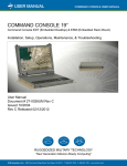
FIELD-READY FIELD-READY COMMAND C O NS O L E 15 User Manual Doc# 27-0002UM Issued 7/99 Rev. 1.2 ZZ Microsystems Microsystems Regulatory FCC INFORMATION 1. Use the power and video cables supplied with the Command Console to help prevent interference with radio and television reception. The use of cables and adapters may cause interference with electronic equipment in the vicinity of this unit. and on, the user is encouraged to try to correct the interference by one or more of the following measures: Reorient or relocate the receiving antenna. Increase the separation between the equipment and receiver. COMMAND C O NS O L E 2. This equipment is pending approval for a Class A digital device, pursuant to certain limits imposed by Part 15 of the FCC rules. These limits are designed to provide reasonable protection against harmful interference in a residential installation. This equipment generates, uses and can radiate radio frequency energy, and, if not installed and used in 15 accordance with the instructions, may cause harmful interference to radio communications. However there is no guarantee that interference will not occur in a particular installation. If this equipment does cause harmful interference, to radio or television reception, which can be determined by turning the equipment off 2 Doc# 27-0002UM Issued 7/99 Rev. 1.2 Connect the equipment into an outlet on a circuit different from that to which the receiver is connected. Consult your dealer or an experienced radio/TV technician for help. 3. If necessary, the user should contact the dealer or an experienced radio/television technician for additional suggestions. The user may find the following booklet, prepared to be the FCC, helpful: How to Identify and Resolve Radio-TV Interference Problems. This booklet is available from the U.S. Government Printing Office, Washington, DC, 20402, Stock No. 00400345-4. Contents STARTING POINT Shipment Contents User Manual System Requirements Product Description 4 4 4 4 5 PREPARATION 6 INSTALL RAILS 7 INSTALL CONSOLE 9 FINAL ADJUSTMENTS 10 SETUP 11 CLOSING CONSOLE 12 OPERATION 13 CONFIGURE MONITOR Setup For Windows 95 or 98 Auto Setup Auto Setup for DOS Auto Setup for Windows 3.1 95, 98 or NT 14 14 15 15 ADJUSTMENTS User Control Features Operation OSD Lock/Unlock On-Screen Display (OSD) OSD Functions 18 18 18 19 19 20 16 3 Doc# 27-0002UM Issued 7/99 Rev. 1.2 MAINTENANCE 23 TROUBLESHOOTING Causes and Corrective Action 24 24 APPENDICES Display Modes Power Management 26 26 27 SPECIFICATIONS Display Specifications Supported Display Modes Communications Power Input Power Consumption Performance Tested Environmental Specifications Regulatory Reliability Specifications Developmental Options 28 28 28 28 28 28 28 28 29 29 29 SUPPORT Further Help Replacing Parts Providing Feedback 30 30 31 31 Y2K COMPLIANCE 32 DRAWINGS 33 SHIPMENT CONTENTS USER MANUAL The Command Console shipping box contains the following: The User Manual comes in two formats: printed hardcopy or CDROM. This Manual is also available on the Z Microsystems website (www.zmicro.com). The Command Console Unit Video Signal Cable AC/DC Power Supply Brick with attached DC cable We recommend you read this manual as follows: AC Power Cable Carefully follow the instructions in the Installation and Testing chapter for hookup and initial control settings. Refer to the Operation chapter for a complete description of all the user controls, and the Maintenance and Troubleshooting chapters for care and correcting any unforeseen problems with the system. The Appendices and References chapters are provided for quickly finding technical information about the Command Console. Setup Diskette User Manual Remember to save your original shipping container and packing material to transport or ship the Command Console. SYSTEM REQUIREMENTS The Command Console works with any computer system that provides industry standard screen formats from 640 x 480 to 1280 x 1024, with up to 75 Hz vertical sync. See the Specifications Table of this Manual for a complete listing of all resolutions supported. The Command Console requires a computer with a suitable onboard subsystems for Video Adapter Card that can support XGA 1024 x 768, SVGA 800 x 600, or VGA 640 x 480 at 60 Hz 4 Doc# 27-0002UM Issued 7/99 Rev. 1.2 PRODUCT DESCRIPTION The Command Console provides a liquid crystal display, a desk work surface and storage for any size keyboard and mouse in a 3.5" high (2U) standard 19" rack or transit case. Specially designed locks on each side of the Command Console hold the compact folded unit securely in place during storage. Release of the two Z-Locks on the front sides of the Console allow it to slide out and the LCD display to quickly swing up into a reading position By lifting up the desktop, the keyboard and mouse can be easily removed and set on top. The lightweight and durable aluminum construction provides exceptional strength in field applications. any vertical-viewing angle up to 100 degrees. The display works effectively with any workstation. The high quality LCD screen provides full color and features up to 1280 x 1024 pixel resolution. An electrostatically-applied and baked-on finish is used for extreme durability for shipboard, airborne, field deployments, and industrial or lab applications where weight and size are very critical. The LCD screen has a backlight control that reduces power and extends the life of the monitor. The side-viewing angle is up to 160 degrees. It can be easily adjusted to 5 Doc# 27-0002UM Issued 7/99 Rev. 1.2 Starting Point TOOLS REQUIRED Required Tools and Equipment Flathead screwdriver with about 10" shaft. Phillips screwdriver with about 10" shaft. Computer Setup Diskette DANGER: To avoid shock hazard: Do not remove the covers around the Command Console. Do not connect or disconnect the Command Console during an electrical storm. The power cord plug must be connected to a properly wired and grounded power outlet. Any equipment to which the Command Console will be attached must also be connected to properly wired and grounded power outlets. PRECAUTIONS In preparation to install the Command Console, take the following precautionary steps: Turn off the electrical power to your computer. NOTE: For the fastest and easiest installation of the Command Console, follow these steps in the sequence they are presented. Verify the Command Console power switch is off. If the Console is off, the light will not be illuminated. 6 Doc# 27-0002UM Issued 7/99 Rev. 1.2 Install Rails SLIDE REMOVAL With the Console sitting on a workbench with the front facing towards you, press down to release the Z-Locks on each side of the front of the Console to slide the side rails back. The slide rail will reach a stop about half way back. The slides should now be separated from the Console. This is a safety stop to prevent the Console sliding out too far while mounted to the rack. Each slide unit includes the slide rail, with the front Z-lock mount and the rear mount. Simultaneously press in the safety catches on each slide rail and slide the side rails all the way off the back of the Console. INSTALL THE SLIDES IN THE CABINET FRAME On the front of the cabinet frame, use three Phillips screws on each side to secure the right and left Z-Lock mounts. DO NOT tighten these screws to allow for adjustment of the Console within the cabinet frame. On the rear of the cabinet frame, use the two Phillips screws to loosely secure the right and left rear slide mount to the cabinet frame. DO NOT tighten these screws fully at this time. 7 Doc# 27-0002UM Issued 7/99 Rev. 1.2 On the slide rails, using a slot screwdriver, loosen off the screw. Repeat on each side. Install Rails Go back on the rear of the cabinet frame, and tighten the slide mount to the cabinet frame. Make sure you hold the slide mounts hard against the rack rail. 8 Doc# 27-0002UM Issued 7/99 Rev. 1.2 Install Console INSTALL THE COMMAND CONSOLE IN THE SLIDES Pull the two Console slides out until they lock. Hold the Console by each side, with the front toward you. Feed the four cables coming out of the Console back through the cabinet frame. Simultaneously press in the catches on each slide and slide the Console all the way into the cabinet frame. The Console should slide in and out easily. Guide the Console into the slides and slide the Console in until it stops. TEST INSTALLATION AND MAKE ADJUSTMENTS Slide the Console in and out several times. The Console should easily close completely. Because of variances in cabinet frames, there may need to be some adjustments of the Console slide system for best fit and movement of the Console in and out. 9 Doc# 27-0002UM Issued 7/99 Rev. 1.2 To be sure the slide and mount assembly are aligned properly, slide the Console in and out several times. If the Console binds during sliding, do the following: Install Console FINAL ADJUSTMENTS OF THE COMMAND CONSOLE Loosen the screws on each of the front Z-Lock mounts. Slide the Console partially out. Use a flathead screw driver to slightly move the Z-Locks out away from the Console. Tighten all the screws on the front Z-Lock mounts. Slide the Console in and out to see if it moves smoothly. 10 Doc# 27-0002UM Issued 7/99 Rev. 1.2 Go back to the rear of the rack and fully tighten the side rail screws. Note: A wrench may be necessary to hold the nut on the other side. Install Console SETTING UP MONITOR KEYBOARD AND MOUSE With both hands, press both the Z-Locks down and Slide the Console all the way out. Using both hands, gently lift the Console screen by the top bar. Open the storage tray top. Align the Keyboard and Mouse cable to pass through the recessed access notch. Close the storage tray top, then place the keyboard and mouse on top of the tray door. Remove the keyboard and mouse. The storage tray door now becomes a workstation for the keyboard and mouse. There should be ample cable to both units for movement around the workstation. 11 Doc# 27-0002UM Issued 7/99 Rev. 1.2 Closing Console CLOSING DOWN THE MONITOR Remove the keyboard and mouse from top. Open the storage tray top. Slide the Console in with both hands. Place the keyboard and mouse inside the tray along with all cables and close door. Press both the Z-Locks down and and slide in the console untill you hear the positive click from the lock. 12 Doc# 27-0002UM Issued 7/99 Rev. 1.2 Using both hands, gently drop the Console screen by the top bar until it lays flat. Operation INSTALLING CABLES 4 cables connect the back of the Console to the computer. Power cable Video cable Keyboard cable Mouse cable To connect the four cables: WARNING: Be sure all electrical power to the cabinet is off before connecting any of the cables. Turn off the computer and all attached devices. WARNING: There is a key guide for alignment on all the cables. Be sure the cable plug and receptacles are aligned properly using the key guide. Misalignment can cause short circuiting. Insert the power plug into a properly grounded electrical outlet. Connect the video cable to the video port on the back of the computer. POWERING UP Switch the Console monitor on by pushing and releasing the power switch marked. Turn on the monitor and then the computer. 13 Doc# 27-0002UM Issued 7/99 Rev. 1.2 Configure Monitor The Command Console offers several methods to set up the monitor, depending on the operating system used for your computer. Use the Setup Diskette and select the setup that is best for your computer operating system. When first used, you must perform Automatic Setup (AUTO SETUP). This procedures sets up the monitor to process the video signals from the computer without image discoloration or smearing. After performing AUTO SETUP, the settings are stored and used each time the monitor is turned on. The Setup Utility included on the Setup Diskette is for display dot patterns. They do not replace or modify the display driver. The Automatic Setup instructions require the monitor to be warmed up for 15 minutes. However, this is not required for normal operation. SETUP FOR WINDOWS 95 OR WINDOWS 98 NOTE: This section must be completed before continuing with the Windows 95 or Windows 98 Auto Setup for the computer. 5. Select the SETTINGS tab. To use the Plug and Play feature in Windows 95 or Windows 98, files should be loaded from the Setup Diskette as follows: 6. Select the CHANGE DISPLAY TYPE button. 7. Select the CHANGE MONITOR TYPE button. 1. Turn the computer off and attach devices. 8. Insert the Setup Diskette into drive A: and select the Have Diskette button. 2. Ensure that the monitor is connected correctly. 3. Turn on the monitor and then the computer. Allow the computer to boot into Windows 95 or Windows 98. The computers Plug and Play code may display a warning that the system hardware has changed. This probably means that it has detected the new monitor for the first time. 9. Select OK. 10. Choose IBM T55A monitor and select OK. The files will be copied from the diskette to the computer hard drive. 11. Close all open windows and remove the diskette. 12. Reboot the computer system. The system will automatically select the maximum refresh rate and corresponding Color Matching Profiles. 4. Open the DISPLAY PROPERTIES window by clicking on START, SETTINGS, CONTROL PANEL and then double clicking on the DISPLAY icon. 14 Doc# 27-0002UM Issued 7/99 Rev. 1.2 Configure Monitor AUTO SETUP NOTE: After making changes in the Setup, the computer must be Rebooted to insure proper changes to the CONFIG.SYS and AUTOEXEC.BAT files. Locate the operating system installed on the computer in the Table below and follow the appropriate instructions. You may choose to run Auto Setup for each operating system that is used. This means that if sometimes the monitor is used while running any version of Windows and sometimes it is also used within DOS (not a DOS window), you must run Auto Setup for both Windows and DOS. You may run versions of Auto Setup in any order. NOTE: Before proceeding with the next section, it is very important that The Setup Diskette for Windows 95 or Windows 98 has been run. NOTE: If your computer does not run with the Setup Diskette shipped with the monitor, refer to Manual Setup. Before beginning Auto Setup for the computer: Make a backup copy of the Setup Diskettes supplied with the monitor. Make sure the computers video mode is set in the range of the supported screen resolution shown in the table in the Reference section. NOTE: The Auto Setup process only applies to the current screen mode. When a new mode is selected, repeat this section to reset the monitor. Perform Auto Setup for each screen mode used. 15 Doc# 27-0002UM Issued 7/99 Rev. 1.2 Configure Monitor AUTO SETUP FOR WINDOWS 3.1, 95, 98 OR NT 1. Turn the monitor on first, then the computer. If the message CHECK SIGNAL CABLE is displayed. If nothing is displayed check: NOTE: If the monitor is in standby mode (STANDBY ON), it may automatically turn off while you are waiting for it to warm up. that the video interface cable is connected properly. the correct video adapter card is installed. the correct support display mode is selected for the computer. NOTE: The size and diversity of the dot pattern varies with the screen resolution. 2. Wait approximately 15 minutes, until the monitor warms up. 3. Drag the icon bar and tool bar, if they are displayed, to the bottom of the screen. 4. Insert the Setup Diskette into the diskette drive. 5. Check the operation system installed on your computer and follow the instructions from the table above. NOTE: Position the mouse pointer at the bottom center of the screen. This allows Auto Setup to run properly. 6. When the test pattern appears, at press the OSD Enter button the bottom of the monitor to display the initial OSD menu. 16 Doc# 27-0002UM Issued 7/99 Rev. 1.2 Configure Monitor 7. Use an Arrow button ( ) to select the Image Lock icon (symbol of Image Lock) and press OSD to access the Enter button function. 8. Using an Arrow button ( ), select Automatic and press the . This actiOSD Enter button vates the Auto Setup procedure, which will optimize the display settings with the provided test pattern. The screen will dim, blink on and off several times, and you may notice small changes to the test pattern. To abort the Auto Setup function, press the Esc key. 9. When finished, the OSD main menu returns. Press the Exit button once to exit from the OSD. 10. Press the Esc key to return to Windows. You have completed the monitor setup for Windows. You have completed the monitor setup for Windows. If you use other operating systems, perform the appropriate AUTO SETUP for those systems. 17 Doc# 27-0002UM Issued 7/99 Rev. 1.2 Monitor Adjustments User Control Features Making adjustments to the Command Console screen is a matter of performing the following easy On-Screen Display steps: Operation Press any of the OSD control buttons to display the main OSD menu. NOTE: The image is already optimized for many display modes, however the user controls can be used to adjust the image to your liking. Use the Arrow buttons to move among the icons. Select an icon and press OSD Enter to access that function. If there is a submenu, you can move between options using the Arrow buttons, then press OSD Enter to select that function. Use the Arrow buttons to make adjustments. NOTE: The settings saved after adjustment and when existing the OSD and will be effective thereafter. Press the Exit button to move backwards through the submenus and exit from the OSD. NOTE: After making adjustments, the Power indicator LED will briefly turn amber to indicate that the new value has been saved. 18 Doc# 27-0002UM Issued 7/99 Rev. 1.2 Monitor Adjustments OSD Lock/Unlock This feature allows you to secure the current control settings, while allowing the user to adjust Brightness and Contrast, so that they cannot be inadvertently changed, you can unlock the OSD controls at any time by using the same procedure. Push and hold the button 10 seconds to Lock or to Unlock. When locked, a LOCKED message will be displayed. On-Screen Display (OSD) Controls NOTE: The LCD monitor needs time to become thermally stable the first time you turn it on each day. Thus, to achieve more accurate adjustments for parameters. Allow the LCD monitor to warm up (be On) for at least 15 minutes before making any screen adjustments. 19 Doc# 27-0002UM Issued 7/99 Rev. 1.2 Monitor Adjustments Initial Appearance of OSD OSD Functions 20 Doc# 27-0002UM Issued 7/99 Rev. 1.2 Monitor Adjustments OSD Functions 21 Doc# 27-0002UM Issued 7/99 Rev. 1.2 Monitor Adjustments OSD Functions 22 Doc# 27-0002UM Issued 7/99 Rev. 1.2 CLEAN MONITOR Maintenance WARNING: To avoid risk of electric shock, do not disassemble the monitor cabinet. Users cannot service the monitor. User maintenance is restricted to cleaning as explained below. • Gently wipe the covers and the screen with a soft cloth. • Remove finger marks and grease with a damp cloth and mild detergent. DO NOT use solvents or abrasives. • Never use flammable cleaning material to clean the monitor or other electrical apparatus. Be sure to turn off the power before you perform any maintenance on the monitor. 23 Doc# 27-0002UM Issued 7/99 Rev. 1.2 Troubleshooting WARNING: Be sure to turn off the power before you perform any maintenance on the monitor. CAUSES AND CORRECTIVE ACTION NOTE: For image problems, you may want to run AUTO SETUP again before consulting to this section. In most cases, AUTO SETUP can fix the problems. 24 Doc# 27-0002UM Issued 7/99 Rev. 1.2 Troubleshooting 25 Doc# 27-0002UM Issued 7/99 Rev. 1.2 Display Modes The display mode the monitor uses is controlled by the computer. Refer to the computer documentation for details on how to change display modes. The image size, position and shape may change when the display mode changes. This is normal and the image can be readjusted using AUTO SETUP and the monitor controls. Unlike CRT monitors, which require a high refresh rate to minimize flicker, TFT technology is inherently flickerfree. If possible, configure the computer for 1024 x 768 addressablility at 60 Hz vertical refresh rate. For the Factor Set Display Modes listed below, the screen image has been optimized during manufacture. FACTORY SET DISPLAY MODES 26 Doc# 27-0002UM Issued 7/99 Rev. 1.2 Display Modes POWER MANAGEMENT To benefit from power management, the monitor must be used in conjunction with a computer that implements the Video Electronics Standards Association (VESA) Display Power Management Signaling (DPMS) Standard. NOTE: If the computer has previously been used with a CRT monitor and is currently configured to a display mode outside the range that the Flat Panel monitor can display, reattach the CRT monitor temporarily until the computer is reconfigured, preferably to 1024 x 768 at 60 Hz. The power management feature is invoked when the computer recognizes that the mouse and keyboard have not been used for a userdefinable period. There are several states as described in the table below. It is recommended that the monitor be switched off at the end of each working day, or whenever it is expected to be unused for long periods during the day. The following is the Power Management Table: 27 Doc# 27-0002UM Issued 7/99 Rev. 1.2 Specifications Display Specifications Display Type Display Area Diagonal Viewing Area Viewing Angle Resolution Color Pixel Size Colors Contrast Ratio Luminance Screen Refresh Input Signal Sync Types AMLCD 15.0 (381 mm) 11.97 (304 mm) x 8.97 (228 mm) 160 degrees (horizontal/vertical) 1024 x 768, RGB Vertical Strip Hor. - 0.297 mm, Ver. - 0.297 mm Full Color (millions) 220:1 (typ) 180 cd/m2 (typ) 75 Hz Analog VGA, SVA, XGA, SXGA Separate, Composite (on H Sync), Sync on Green BNC, 13W3, HD15 58ms (type) black to white 80 MHz Video Connectors Response Time Clock Frequency Supported Display Modes VESA Standard modes between Horiz. Frequency 30 kHz - 61 kHz Vert. Frequency 56 Hz - 75 Hz Communications VESA DDC 2B Power Input Supply Voltage 90 260 Vac 60/50+/- 3hZ Max. Supply Current 1.0 A at 120 Vac Power Consumption Normal Operation < 40 W DPMS Standby < 5W DPMS Suspend < 5W DPMS off < 5W Performance Tested Acoustic signal data, (taped and generated), electron-optical live video. Cold soak and display photometric/radiometric characteristics Environmental Specifications Temperature Humidity Altitude -10 to +35 C Operating -20 C to +60 C Nonoperating -20 C to +60 C Shipping 10% to +80% Operating 5% to +95% Noncondensing 5% to +95% Shipping 0 to 15,000 ft. Operating 0 to 40,000 Nonoperating 28 Doc# 27-0002UM Issued 7/99 Rev. 1.2 Specifications Shock 15 G, 11 mS Operating 30 G, 11mS Nonoperating Bench handing per MIL-STD-810E Vibration, Random 3.0G RMS, 20-2,000 Hz Operating 4.0G HMS, 20-2,000Hz Nonoperating Enclosure Weight Sand and Dust Rain NEMA 4/12 at front panel 24 lb. 5.5 M.P.H. for 25 minutes Per MIL-STD-810E, method 506.3, procedure II Non Nutrients/contaminants Fungus Regulatory EM/RFI Safety Reliability Specifications Mean-time-between-failure (MTBF) Operating Life Quality Assurance Maintainability MTTR FCC Class A, MIL-STD-401 (optional) (Pending Approval) FCC Class A: UL 1950 20,000 hours (Bellcore) 10 years without major overhaul Complies with MIL-1-45208 and MILQ-9858 <30 minutes or less Developmental Options Touch panel 28 VDC operation Elapsed time meter Customer specified mounting Interchangeably power supply 29 Doc# 27-0002UM Issued 7/99 Rev. 1.2 Support FURTHER HELP If you are unable to correct the problem yourself, contact: Z Microsystems at: (858) 657-1000 Fax: (858) 657-1001 Website: www.zmicro.com NOTE: For image problems, run AUTO SETUP again before consulting this section. In most cases, AUTO SETUP can fix the problems. See the Auto Setup section for details. Before calling, please have available as much of the following information as possible: 1. Model and serial number from the label on the monitor. 2. Purchase P.O. 3. Description of problem. 4. Computer type and model. NOTE: If possible, stay by the computer. The Z Microsystems Technical Support Representative may wish to go through the problem over the telephone. 5. System configuration (hardware fitted, etc.). 6. System BIOS version number. 7. Operating System and version number. 8. Display driver version number. 9. Video Adapter Type. NOTE: More help, late-breaking news and details of the latest accessories for these products may be found on the worldwide web at: http:// www.zmicro.com 30 Doc# 27-0002UM Issued 7/99 Rev. 1.2 Support If the Z Microsystems Technical Support Engineer determines that the product needs to be replaced, a Customer Service representative will issue a Return Material Authorization (RMA) number and return address. An RMA number is required to return a product to Z Microsystems, regardless of the reason for the return. The following information is required when returning Z Microsystems products: 1. Model number 2. Serial number 3. Date of purchase 4. Proof of purchase (use the invoice or packing slip) 5. Customer ship-to address and any special shipping requirements 6. Specific and detailed description of the problem PROVIDING FEEDBACK We value feedback on our products, their performance, any problems and constructive suggestions. Please send such productive information in writing to: Customer Service Z Microsystems 5945 Pacific Center Blvd., Suite 509 San Diego, CA 92121-4309 or www.zmicro.com 31 Doc# 27-0002UM Issued 7/99 Rev. 1.2 Compliance Y2K COMPLIANCE Z Microsystems has achieved full Y2K Compliance. In late 1997, the companys senior management assigned a Y2K Project Team that consists of a cross-functional representation from information technology, procurement, manufacturing, test and development, finance, general affairs, engineering, marketing and facilities organizations to address the Year 2000 issues. The Assessment/Rectification Phase of the Year 2000 efforts and full compliance for all mission critical internal systems were accomplished as scheduled by the end of Q1, 1999. Contingency development and validation of the companys overall Year 2000 readiness will continue through 1999. The following strategically important categories have been assessed for Year 2000 readiness: Suppliers and Service Providers Readiness. All major strategic suppliers are assessed to be Year 2000 compliant. Most of the companys service providers compliance efforts will continue through 1999. Major concerns and efforts will be focused on the companys shipping companies in 1999. Z Microsystems Internal Systems Z Microsystems Products All mission critical internal systems are determined to be fully Year 2000 Compliant. A few minor Year 2000 Related issues need to be addressed in 1999. All Z Microsystems products are in full compliance. The company MIS has taken the lead and worked with the Finance Department to develop comprehensive Year 2000 Contingency Plans for the company mission critical application systems to assure the continuity of daily business. 32 Doc# 27-0002UM Issued 7/99 Rev. 1.2 Drawings 33 Doc# 27-0002UM Issued 7/99 Rev. 1.2 Drawings 34 Doc# 27-0002UM Issued 7/99 Rev. 1.2 Z Microsystems, Inc. 5945 Pacific Center Blvd., Suite 509 San Diego, CA 92121 Phone: (858) 657-1000 Fax; (858) 657-1001 Website: www.zmicro.com Copyright 1999 Z Microsystems, Inc. All Rights Reserved Doc# 27-0002UM Issued 7/99 Rev. 1.2