1
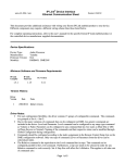
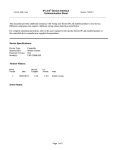
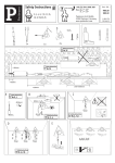
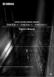
IP Link® De vice Interface
Communication Sheet
yama_25_4013_3.pke
Revision: 8/20/2010
This document provides additional assistance with wiring your Extron IP Link enabled product to your device.
Different components may require a different wiring scheme than those listed below.
For complete operating instructions, refer to the user's manual for the specific Extron IP Link enabled product or
the controlled device manufacturer supplied documentation.
Device Specifications:
Device Type:
Manufacturer:
Firmware Version:
Model(s):
Audio Processor
Yamaha
N/A
DME24N, DME4io-C, DME64N, DME8i-C, DME8o-C
Version History:
Driver
Version
Date
IP Link
Compiler
GC
Version
3
8/19/2010
1.4.0
3.0.3
Modified driver to have 6 different set of commands.
1
1/14/2010
1.4.0
3.0.2
Initial version.
Notes
Driver Notes:
Driver is not recommended for passthrough mode.
For user configuration flexibility, the driver contains 6 groups of configurable commands. The commands are
group in Set A, Set B, Set C, Set D, Set E and Set F. In order for any Parameter and Relative command to work
properly, an Index should be selected first. Index should be unique between the different set of commands. For
example, Set A Index will be use for Set A Parameter and Set A Relative and in the same manner for the other
commands. A step size needs to be selected in order for the Relative command to work correctly. Set A Step Size
will work with Set A Relative. This applies to the other set of commands also.
.
Page 1 of 5
IP Link® De vice Interface
Communication Sheet
yama_25_4013_3.pke
Revision: 8/20/2010
Control Commands & States:
Audio Mute
On
Off
Pre set Re call
1-24
Se t A Index
1-255
Se t A Paramete r
0 to 1023 in steps of 1
Se t A Relative
Up
Down
Se t A Ste p Size
1
2
4
8
16
32
64
128
256
Se t B Index
1-255
Se t B Parame te r
0 to 1023 in steps of 1
Se t B Relative
Up
Down
Se t B Ste p Size
1
2
4
8
16
32
64
128
256
Se t C Index
1-255
Se t C Paramete r
0 to 1023 in steps of 1
Se t C Relative
Up
Down
Se t C Ste p Size
1
2
4
8
16
32
64
128
256
Se t D Index
1-255
Se t D Paramete r
0 to 1023 in steps of 1
Se t D Relative
Up
Down
Se t D Ste p Size
1
2
4
8
16
32
64
128
256
Se t E Index
1-255
Page 2 of 5
IP Link® De vice Interface
Communication Sheet
yama_25_4013_3.pke
Revision: 8/20/2010
Se t E Parame te r
0 to 1023 in steps of 1
Se t E Relative
Up
Down
Se t E Ste p Size
1
2
4
8
16
32
64
128
256
Se t F Inde x
1-255
Se t F Paramete r
0 to 1023 in steps of 1
Se t F Relative
Up
Down
Se t F Ste p Size
1
2
4
8
16
32
64
128
256
Page 3 of 5
IP Link® De vice Interface
Communication Sheet
yama_25_4013_3.pke
Status Available:
Connection Status
Connected
Disconnected
Se t A Paramete r
0 to 1023 in steps of 1
Se t B Parame te r
0 to 1023 in steps of 1
Se t C Paramete r
0 to 1023 in steps of 1
Se t D Paramete r
0 to 1023 in steps of 1
Se t E Parame te r
0 to 1023 in steps of 1
Se t F Paramete r
0 to 1023 in steps of 1
MLC62 Supported Commands:
Audio Mute
On
Pre set Re call
1-24
Off
Page 4 of 5
Revision: 8/20/2010
yama_25_4013_3.pke
IP Link® De vice Interface
Communication Sheet
Revision: 8/20/2010
Cable and Adapter Requirements:
F/F RS-232 Null Modem Serial Cable
Notes for the Device:
When configuring the Remote Control Setup List, Type needs to be set to Curve Table in order for driver to work
correctly.
Serial communication:
Port Type : RS-232
Baud Rate: 38400
Data Bits: 8
Parity: None
Stop Bits: 1
Flow Control: None
Pin Assignments Diagram:
Note: Captive screw connector may also be used as a serial connection.
General Notes:
Page 5 of 5