1
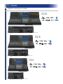
CL Series
GENERAL SPECIFICATIONS
Sampling frequency rate
Internal:
ANALOG INPUT SPECIFICATIONS
44.1kHz, 48kHz
Input terminal
External: 44.1kHz (+4.1667%, +0.1%, -0.1%, -4.0%) ±200ppm
48kHz (+4.1667%, +0.1%, -0.1%, -4.0%) ±200ppm
Signal Delay
Less than 2.5 ms OMNI IN to OMNI OUT (@fs=48kHz)
Total harmonic distortion*1
Less than 0.05% 20Hz to 20kHz @+4dBu into 600Ω
GAIN
Actual
source
impedance
Dynamic range
(maximum level to noise level)
Hum & noise level*2
(20Hz to 20kHz), Rs=150Ω
Crosstalk (@1kHz)
+17dB
CL5/CL3/CL1: 170W, Internal Power Supply
CL5/CL3/CL1: 200W, Simultaneous use of Internal PSU and
External PW800W
CL5: 1053 x 299 x 667mm (41.5" x 11.8" x 26.3")
CL3: 839 x 299** x 667mm (33.1" x 11.8" x 26.3")
CL1: 648 x 299** x 667mm (25.5" x 11.8" x 26.3")
CL5: 36kg (79.4lbs)
CL3: 29kg (63.9lbs)
CL1: 24kg (52.9lbs)
Dimensions (W x H x D)
Weight
-62dBu
-42dBu
-34dBu
-14dBu
+6dBu
-33dBu
-13dBu
+7dBu
-10dBu
+10dBu
+30dBu
-70dBu
-60dBu
-40dBu
-26dBu
-16dBu
+4dBu
Connector
XLR3-31 type*
3kΩ
+64dB
TALKBACK
50-600Ω Mics
& 600Ω Lines
10kΩ
+20dB
Power consumption
-82dBu
-6dB
Input Gain=Min.
+48V
AC110V-240V, 50/60Hz
Max.
before clip
50-600Ω Mics
& 600Ω Lines
OMNI IN 1-8
+0.5, -1.5dB 20Hz to 20kHz, refer to +4dBu output @1kHz,
OMNI IN to OMNI OUT
112dB typ., DA Converter,
108dB typ., OMNI IN to OMNI OUT, Input Gain = Min.
-128dBu Equivalent input noise, Input Gain=Max.,
-84dBu Residual output noise, ST master off
-100dB*3, Adjacent OMNI IN/OMNI OUT channels
Phantom Power
Power requirements
Nominal
10kΩ
+18dB
CH INPUT to OMNI OUT
Input level
Sensitivity
+66dB
OMNI IN to OMNI OUT
Input Gain=Min.
Frequency response
For use with
nominal
XLR3-31 type*
ANALOG OUTPUT SPECIFICATIONS
Output terminal
Actual source
impedance
For use with
nominal
75Ω
600Ω Lines
OMNI OUT 1-8
*1 Total harmonic distortion is measured with a 18dB/Oct filter @80kHz.
*2 Hum & noise level is measured with a 6dB/oct filter @12.7kHz; equivalent to 20kHz filter with
infinite dB/Oct attenuation.
*3 Crosstalk is measured with a 30 dB/octave filter @22kHz.
** Excluded MBCL optional meter bridge.
PHONES
GAIN SW
Output terminals
Max.
before clip
Nominal
+24dB
+4dBu
+24dBu
+18dB
-2dBu
+18dBu
8Ω Phones
—
75mW
150mW
40Ω Phones
—
65mW
150mW
Connector
XLR3-32 type*
15Ω
ST Phone Jack**
DIGITAL I/O SPECIFICATIONS
Terminal
Format
Primary/Secondary
Dante
Data length
Level
24bit or 32bit 1000Base-T
Audio
Connector
64ch Input/64ch Output
etherCON Cat5e
@48kHz
DIGITAL OUTPUT SPECIFICATIONS
Terminal
DIGITAL OUT
AES/EBU
Format
Data length
Level
Connector
AES/EBU Professional
Use
24bit
RS422
XLR3-32 type*
I/O Slot (1-3) SPECIFICATIONS
Each I/O Slot accepts a Mini-YGDAI card. Only Slot1 has a serial interface.
CONTROL I/O SPECIFICATIONS
Terminal
MIDI
WORD CLOCK
Format
Level
IN
MIDI
—
OUT
MIDI
—
IN
—
TTL/75Ω terminated
OUT
—
TTL/75Ω
—
—
GPI (5IN/5OUT)
NETWORK
IEEE802.3
LAMP (CL5=3, CL3=2, CL1=1)
—
10BASE-T/100Base-TX/
0V - 12V
USB HOST
USB 2.0
—
EXT DC IN
—
—
Meter Bridge (CL3/CL1 only)
—
—
*1. Input pins: Internal TTL-level pull-up
resistors provided (47kΩ). Output pins:
Open-drain output (Vmax = 12V, max.
sink current/pin = 75mA)
Power pins: Output voltage Vp = 5V,
max. output current Imax = 300mA
*2. Pin 4 = +12V, Pin 3 = GND, lamp
rating 5W. Software voltage control.
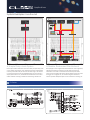
DIMENSIONS
unit : mm
15
15
15
374
389
299
201
667
1053
CL5
299
201
667
535
667
299
201
130
839
CL3
130
648
CL1
130