1
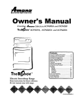
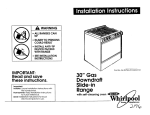
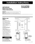
IMPORTANT:
Read and save
these instructions.
IMPORTANT:
Installer: Leave Installation Instructions
with the homeowner,
Homeowner:
Keep Installation Instructions
for future reference.
Save Installation Instructions for local
electrical inspector’s use.
Note: This cookop
is manufactured
for use with Natural
gas. To convert for use with L.P./Propane gas
requires Kit No. 4372174 (for use with model
SC 8630 EB series only), available from your
Whirlpool dealer or authorbed
parts drstributor.
Part No, 202887-l
Sealed Burner
Cooktop
100 Rev. 3/4372169
Rev. C
Before you start...
Proper installation is your responsibility.
Make
sure you have everything
necessary for
correct installation.
It is the responsibility of
the installer to comply with the installation
clearances
specified on the serial/rating
plate. The serial/rating
plate can be found
on the underside of the cooktop burner box
Note: This cooktop is manufactured
for use
with Natural gas. To convert for use with
L.P./Propane gas requires Kit No. 4372174,
available
from your Whirlpool dealer or
authorized parts distributor.
Product
Grounded
“Electrical
This cooktop is not approved
for use with downdraft
vent systems.
Check location where cooktop will be
installed. The location should be away frorri
strong draft areas, such as windows, doors
and strong heating vents or fans. The
cooktop should be located for convenient
use in the ktchen
ALL OPENINGS IN THE WALL OR FLOOR
WHERE THE COOKlOP IS TO BE INSTALLED
MUST BE SEALED.
-
is required.
See
Proper gas supply connection
must be
available.
See “Gas supply requirements.”
Countertop
opening dimensions that are
shown must be used. Given dimensions
provide required 0” clearance.
Important: Observe all governing
codes
and ordinances.
Failure to meet codes and
ordinances
could lead to fire or electrical
shock.
WARNING: If the information
in
this manual is not followed
exactly, a fire or explosion may
result causing property damage,
personal injury or death.
Dimensions
-Width
electrical
outlet
requirements.”
30”
-
height
-
Do Not store or use gasoline or
other flammable
vapors and
liquids in the vicinity of this or
any other appliance.
- WHAT TO DO IF YOU SMELL GAS
l
Do Not try to light any
appliance.
l
Do Not touch any electrical
switch; Do Not use any phone
in your building.
l
Immediately
call your gas
supplier from a neighbor’s
phone. Follow the gas
supplier’s instructions.
l
If you cannot reach your gas
supplier, call the fire
department.
- Installation and service must be
performed
by a qualified
installer, service agency or the
gas supplier.
3”
is required. If cabine
has a drawer, a 3” depth clearance
from
the countertop
to the top of the drawer (or
other obstruction)
in base cabinet is
required.
30” min. base cabinet
Cabinet
and Cutout Dimensions
30” min.
1” min. space
between adjacent
cooktops
I
-_)
Minimum distance
to nearest rear
combustible
surface
above cooktop
p&d
13” max.
-UDDer
\I
-
19” opening
Do Not obstruct
depth
and ventilation
Fire Hazard
the flow of combustion
air.
Personal Injury Hazard
Avoid installing cabinet storage above thi
cooking surface. If cabinets are already
installed, reduce the hazard of reaching
over a heated cooking surface by
installing a range hood. The range hood
should extend a minimum of 5 inches out
from the bottom front of the cabinets.
Reaching over a heated cooking surface
could result in a serious burn or other
personal injury.
Important: Observe all
governing
codes and
ordinances.
Failure to meet codes
and ordinances
could
lead to fire or electric
shock.
Electrical Shock Hazard
It is the customer’s responsibility:
l To contact
a qualified electrical
installer
l To assure
that electrical
installation
is
adequate
and in conformance
with
National Electrical Code ANSI/NFPA
70 - latest edition’ and all local codes
and ordinances.
Failure to do so could result in fire,
electrical shock or other personal injury.
nn ,.-.
Nnt r”‘“”
ninrh
+hn
-,,,_
I
I
Clearance
Take special care when drilling holes into
the wall for electrical
wiring. Electrical
wires may be concealed
behind the wall
Eovering.
-ailure to do so could result in fire,
electrical shock or other personal injury.
power supply cord
between the cooktoo
and cabinet.
Dimensions
***
Note: 30” min. when bottom
36” min. clearance
wood
surface
Panel A
above
cooktop
or metal sheet
between
01
the
Mobile
home installation
TFle installation of this cooktop must conform
tc the Manufactured
Home Construction
and Safety Standards, Title 24 CFR, Part 3280
(formerly the Federal Standard for Mobile
Home Construction
and Safety, Title 24, HUD
Pr~rt 280); or when such standard is not
applicable,
the Standard for Manufactured
Home Installations 1982 (Manufactured
Home Sites, Communities
and Setups), ANSI
A225 1/NFPA 501 A - 1987, or latest edition,
or with local codes.
Copies of the standards listed may be
obtained
from:
*National Fire Protection Association
Batterymarch
Park
Quincy, Massachusetts
02269
**American
Gas Association
1515 Wilson Boulevard
Arlington, Virginia 22209
shutoff valve
Tools needed for
installation:
Recommended
F.
The supply line shall be equipped
with
an approvedshutoff
valve. This v&e shoulc
be located in the same room as the
cooktop and should be in a location that
allows ease of opening and closing. Do Not
block acce’ss to shutoff valve. The valve is
for turning on or shutting off gas to the
appliance.
ipe wrench
flat-blade
screwdriver
!?”
For your personal safety, this appliance
must
be grounded.This
appliance
is equipped
wl-h a 3-prong grounding
plug. To minimize
possible shock hazard, the cord must be
plugged into a mating 3-prong groundingtype wall receptacle,
grounded
in
accordance
with the National Electrical
Code ANSI/NFPA 70 - latest edition* and
local codes and ordinances.
See Figure 1.
If a mating wall receptacle
is not available,
it
is the personal responsibility and obligation
of the customer to have a properly
grounded,
S-prong wall receptacle
installed
by a qualified electrician.
H
n The regulator
must be checked at a
minimum 1-inch water column above the se1
pressure. The inlet pressure to the regulator
should be as follows for both operation
and
checking the regulator setting:
tape measure/ruler
Gas supply
requirements
NATURAL GAS:
Minimum pressure 5 inches W.C.
Maximum pressure 14 inches W.C.
codes
method
fittings must be used to obtain an in-line
connection
to the cooktop
All strains must
be removed from the supply and fuel lines
so cooktop will be level and in line.
’ adjustable
wrench
Observe all governing
ordinances.
grounding
supply
cord
Figure 1
Now start...
With cooktop
in kitchen.
and
Fire Hazard
Cooktop must be connected
to a
regulated gas supply.
Do Not use an open flame to test for leaks
from gas connections.
New, A.G.A. design-certiiied,
flexible gas
line should be used when codes permit.
Failure to follow these instructions could
result in a fire, explosion or personal injury.
l
l
l
A
q This installation
must conform with
local codes and ordinances.
In the
absence of local codes, installations must
conform with American
National Standard,
National Fuel Gas Code ANSI 2223.1 latest edition.**
I n Line pressure testing:
Testing above l/2 psi (14 inches W.C.)
W-W
The cooktcp and its individual shutoff valve
must be disconnected
from the gas supply
pping system during any pressure testing of
that system1 at test pressures greater than
l/2 psig (3.5kPA).
Testing at l/2 psi (14 inches W.C.) (gauge)
or lower
The cooktop must be isolated from the gas
supply piping system by closing its rrdividual
manual shutoff valve during any pressure
testing of tl?e gas supply piping system at
test pressures equal to or less than l/2 psig
(3.5kPA).
u-
=
Remove foam shipping blocks and
tape from cooktop. Untape power cord
A
Electrical
requirements
2
n
Remove pressure regulator,
hardware
package,
burner grates and
caps package
from shipping box.
B
n
Input ratings shown on the
serial/rating
plate are for elevations up to
2,000 feet. For elevations above 2,000 feet,
ratings are reduced at a rate of 4% for each
1,000 feet above sea level.
C
w The sealed gas cooktop is
manufactured
for use with NATURAL gas,
Conversion to L.P. gas can be made with
Kit No. 4372174, available from your
Whirlpool dealer or authorized
parts
distributor.
No attempt shall be made to convert the
appliance
from the gas specified on the
serial/rating
plate for use with a different
gas without consulting the servicing gas
supplier. Conversion must be done by a
qualified service technician
using only the
kit number specified.
D
n Provide a gas supply line of 3/4”
rigid pipe to the cooktop location
A smaller
size pipe on long runs may result in
insufficient gas supply. Pipe-joint
compounds,
made for use with NATURAL
and L.P. gas, must be used.
E
If local codes and ordinances
permit, A.G.A. design-certified,
flexible
metal tubing is recommended
for
connecting
this cooktop to the gas supply
line. Do Not kink or damage the flexible
tubing when moving the cooktop. A l/2”
male pipe thread is needed for connection
to pressure regulator female pipe threads,
n
Panel 6
Electrical Shock Hazard
Electrical ground is required on this
appliance.
Do Not ground to a gas pipe.
Do Not modify the power supply cord
plug. If plug will not fit the outlet, have a
proper outlet installed by a qualified
electrician.
Do Not have a fuse in the neutral or
grounding
circuit. A fuse in the neutral o
grounding circuit could result in an
electrical
shock.
Do Not use an extension cord with this
appliance.
Check with a qualified electrician
if you
are in doubt as to whether the appliance
is properly grounded.
Failure to follow these instructions could
result in serious injury or death.
l
l
l
Property Damage
Lift entire cooktop up from cutout when
repositioning
cooktop in countertop
opening.
Failure to do so could
scratch
countertop.
l
l
l
If codes permit and a separate
wire is used, it is recommended
qualified electrician
determine
grounding
path is adequate.
grounding
that a
that the
A 120~volt. 60-Hz, AC-only, 15ampere,
fused electrical supply is required.
A timedelay fuse or circuit breaker is
recommended
It is recommended
that a
separate circuit serving only this appliance
be provided.
Electronic ignition systems operate within
wide voltage limits, but proper grounding
and polarity are necessary.
In addition to
checking that the outlet provides 120-volt
power and is correctly grounded,
the outlet
must be checked
by a qualified electrician
to see if it is wired with correct polarity. A
wiring di’slgram is provided in the literature
package.
t
I
-7
3
n
Insert cooktop into countertop
cutout. Do Not remove protective
film from
loam tape. Center cooktop In cutout.
Check that front edge of cooktop is parallel
to front edge of countertop
Check that all
required clearances
are met and that
cooktop is properly positioned
IJse a pencil to mark a line along the rear of
Icooktop on countertop
(to align cooktop in
:Step 5).
protective
,.a
_
n
Remove cooktop
‘rom cutout and place it
upside down on a
3rotected
surface.
foam
tape
?emove protective
film from foam tape.
Do Not remove foam tape. The foam tape
seals cooktop to countertop
for proper gas
combustion
and prevents liquids from
leaking under cooktop
Electronic Ignition
initial lighting
Numbers
correst3ond
System-
Cooktop burners use electronic
igniters in
place of standing pilots. When the cooktop
ccntrol knob is pushed in and turned to the
“LITE” position, the system creates a spark to
lignt the burner. This sparking continues until
the control knob is turned to the desired
se-ting.
OFF
to
88
n
5
n
Insert cooktop into cutout while
aligning rear of cooktop with pencil line.
Check that cooktop is parallel to the front
edge of countertop.
Lift the entire cooktop
to make adjustments
so that the foam tape
can seal properly.
9
n Use Ipipe-joint compound
made for
use with NATURAL and L.P. gas to seal all
gas connections.
If flexible connectors
are
used, be certain connectors
are not kinked
shutoff valve
Electrical Shock/Fire Hazard
Disconnect
power supply cord from wall
receptacle
before servicing cooktop.
Failure to do so could result in serious
injury or death.
Product Damage
Do Not overtighten
screws.
Overtightening
screws could
cooktop surface.
damage
10
n Open the shutoff valve in the gas
supply line. Wait a few minutes for gas to
move through the gas line.
Fire Hazard
Do Not use an open flame to test for
leaks from gas connections.
Checking for leaks with a flame may
result in a fire or explosion.
ct
cooktop burners. Push in and turn each
control knob to “LITE” position. The flame
should light within 4 seconds. Do Not leave
the knob in the “LITE” position after burner
lights.
If Iburners do not light properly, turn control
krob to the “OFF” position. Check that
burner cap is in the proper position. Check
that power supply cord is plugged in and
that the circuit breaker or house fuse has
not blown. Check that the shutoff valve is in
the “ON” position. Check operation
again.
If ‘a burner does not light at this point,
contact your Whirlpool dealer for
assistance.
15
n After burner lights, turn
control knob to ‘HI” position, Check
each cooktop burner for proper
flame. The small inner cone should
have a very distinct blue flame
approximately
l/2” long. The outer cone
not as distinct as the inner cone.
is
11
6
w
Insert one clamp through each slot
located on the sides of the burner box.
Secure cooktop to countertop
by handtightening
each screw. Do Not over-tighten
screws.
n
n
Use a brush and liauid detergent
to test all gas connections
for ieaks. Bubbles
cround connections
will indicate a leak. If a
leak appears, shut off gas valve controls
and adjust connections.
Then check
connections
again NEVER TESTFOR GAS
LEAKS WITH A MATCH OR OTHER FLAME.
Clean all detergent
solution from cooktop.
7
n
Install the pressure regulator with the
arrow on the regulator pointing up toward
unit and in a position where you can reach
the access cap.
/
1
I
12
I Plug the power supply
the grounded
outlet.
Fire Hazard
Do Not make connection
too tight. The
regulator is die cast.
Overtightening
may crack regulator
resulting in a gas leak and possible fire or
explosion.
l/2” nipple
flexible
connector
locating
cord into
\A
t
shutoff valve
All connections
8
l/2” nipple
~~~~~~
cooktop,
t
pressde
regulator
must be wrench-tightened.
n Assemble the flexible connector
from the gas supply pipe to the pressure
regulator in order: manual shutoff valve,
l/2” nipple, l/2” adapter, flexible
connector,
l/2” adapter, and l/2” nipple
Panel C
Remove the surface burner control knob.
Insert a flat-blade
screwdriver
into the
hollow valve stem and engage the slotted
screw inside. Flame size can be increased
or decreased
with the turn of the screw.
Adjust flame until you can quickly turn knob
from “LITE” to LOWEST POSITION without
extinguishing
the flame. Flame should be as
small as possible without going out.
tabs -F<
ignitor L
,,,A
-5.~. . d
electrode
f
kY2
rnanuai
n Push in and turn each control
knob to the “LO” (or simmer) setting. The
“1.0” setting of each burner has been
factory set to the lowest setting available to
provide reliable reignition of the burner. If it
does not stay lit on the ‘LO” setting. Check
“LO” setting as follows:
a. Turn control to “LITE” until burner ignites.
b. Quickly turn knob down to LOWEST
POSITION.
c. If burner goes out, readjust valve as
follows:
read
your
Whirlpool
Use &
~rrirn
13
Place trim rinas
Find the two locating tabs
cap and mount cap over
burner base. Place burner
burners and caps.
n
over each burner.
under the burner
the slots in the
grates over
1 Congratulations
1
If cooktop does not
operate...
If you need
asshtance...
Check that the circuit breaker is not
tripped or house fuse blown. Check that
power supply cord is plugged into wall
receptacle.
Check that gas valves are
turned to the “ON” position.
The Whirlpool Consumer Assistance Center
will answer any questions about operating
or maintcining
your cooktop not covered in
the Installation Instructions. The Whirlpool
Consumer Assistance Center is open 24
hours a day, 7 days a week. Just dial,
l-(800) 253- 130 1 - the call is free.
A more detailed troubleshooting
checklist
provided in the Use and Care Guide,
is
If you need service...
When you call, you will need the cooktop
model number and serial number. Both
numbers can be found on the serial/rating
plate located on the underside of the
cooktop /burner box.
In the event that your Whirlpool appliance
should need service, call the dealer from
whom you purchased
the appliance
or a
Whirlpool-authorized
service company.
A
Whirlpool-authorized
service company
is
listed in the Yellow Pages of your telephone
directory under “Appliances
- Household
- Major - Service or Repair” You can also
obtain the service company’s
name and
telephone
number by dialing, free, within
the continental
United States, the Whirlpool
Consumer Assistance Center telephone
number, l-(800) 253-1301, A special
operator will tell you the name and number
of your nearest Whirlpool-authorized
service
company.
Maintain the quality built Into your Whirlpool
appliance
- call a Whirlpool-authorized
service company.
Care, cleanfng and
maintenance
If removing the cooktop is necessary for
cleaning or maintenance,
shut off gas
supply. Disconnect the gas and electric
supply. Remove the mounting bracket on
the right and left side of burner box. After
disconnecting
the gas and electric supply,
finish removing the unit for servicing and
cleaning. Reinstall in reverse order and
check gas connection
for leaks.
Part No. 202887-l 100 Rev. 3/4372169
01994 Whirlpool Corporation
Rev, C
Prepaced
by Whirlpool
Corporation,
Berton
Harbor, Michigan
49022
Printed in Canada