1
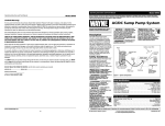
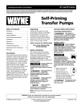
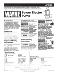
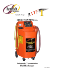
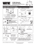
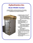
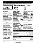
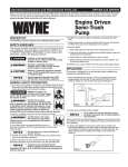
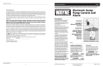
Model ISP40
Operating Instructions and Parts Manual
Operating Instructions and Parts Manual
Model ISP40
Limited Warranty
For two years from the date of purchase, Wayne Water Systems (“Wayne”) will repair or replace, at its option, for the
original purchaser any part or parts of its Sump Pumps or Water Pumps (“Product”) found upon examination by Wayne to be
defective in materials or workmanship. Please call Wayne (800-237-0987) for instructions or see your dealer. Be prepared to
provide the model and serial number when exercising this warranty. All transportation charges on Products or parts
submitted for repair or replacement must be paid by purchaser.
Please completely read and save these instructions. Read carefully before attempting to assemble, install, operate or
maintain the product described. Protect yourself and others by observing all safety information. Failure to comply
with instructions could result in personal injury and/or property damage! Retain instructions for future reference.
AC/DC
Sump Pump System
Record Serial Number here. (Serial
This Limited Warranty does not cover Products which have been damaged as a result of accident, abuse, misuse, neglect,
improper installation, improper maintenance, or failure to operate in accordance with Wayne’s written instructions.
Number is found on Pump Housing)
THERE IS NO OTHER EXPRESS WARRANTY. IMPLIED WARRANTIES, INCLUDING THOSE OF MERCHANTABILITY AND
FITNESS FOR A PARTICULAR PURPOSE, ARE LIMITED TO THREE YEARS FROM THE DATE OF PURCHASE. THIS IS THE
EXCLUSIVE REMEDY AND ANY LIABILITY FOR ANY AND ALL INDIRECT OR CONSEQUENTIAL DAMAGES OR EXPENSES WHATSOEVER IS EXCLUDED.
Description
Some states do not allow limitations on how long an implied warranty lasts, or do not allow the exclusions or limitations of
incidental or consequential damages, so the above limitations might not apply to you. This limited warranty gives you
specific legal rights, and you may also have other legal rights which vary from state to state.
In no event, whether as a result of breach of contract warranty, tort (including negligence) or otherwise, shall Wayne or its
suppliers be liable for any special, consequential, incidental or penal damages including, but not limited to loss of profit or
revenues, loss of use of the products or any associated equipment, damage to associated equipment, cost of capital, cost of
substitute products, facilities, services or replacement power, downtime costs, or claims of buyer’s customers for such
damages.
You MUST retain your purchase receipt along with this form. In the event you need to exercise a warranty claim, you MUST
send a copy of the purchase receipt along with the material or correspondence. Please call Wayne (800-237-0987) for return
authorization and instructions.
DO NOT MAIL THIS FORM TO WAYNE. Use this form only to maintain your records.
MODEL NO._______________ SERIAL NO.__________________________
INSTALLATION DATE_____________
ATTACH YOUR RECEIPT HERE
The AC/DC Sump Pump System
includes a submersible sump pump
and a Power Supply/Battery Charger
(PS/BC). Backup power is supplied by
two 12 volt batteries (not included).
The system is designed for home sump
applications. When an electrical power
outage occurs, the PS/BC automatically
switches the sump pump to battery
power so it will continue to pump
water. There is no need for a back up
sump pump. Using LED’s (Light
Emitting Diodes), the PS/BC also alerts
you to potential problems.
This pump is not
designed to handle
salt water, brine, laundry discharge,
water softener, sewage, graywater or
any other application which may
contain caustic chemicals and/or
foreign materials. Pump damage could
occur if used in these applications and
will void warranty.
NOTICE
Do not
!
use to
pump flammable or explosive
fluids such as gasoline, fuel
oil, kerosene, etc. Do not use
in a flammable and/or explosive
atmosphere. Personal injury and/or
property damage could result. Only use
pump to pump clear water.
DANGER
All wiring must be
!
performed by a
qualified electrician.
WARNING
Battery Jumper Wire
Pump
Stainless Steel
Filter
AC Circuit
Breaker
Power
Supply/
Battery
Charger
(PS/BC)
Battery
Cables
Safety Guidelines
This manual contains information that
is very important to know and
understand. This information is
provided for SAFETY and to PREVENT
EQUIPMENT PROBLEMS. To help
recognize this information, observe the
following symbols.
Danger indicates
!
an imminently
hazardous situation which, if not
avoided, will result in death or serious
injury.
DANGER
Warning indicates a
! WARNING potentially
hazardous situation which, if not
avoided, could result in death or
serious injury.
Caution indicates a
!
potentially
hazardous situation which, if not
avoided, may result in minor or
moderate injury.
CAUTION
Notice indicates
important
information, that if not followed, may
cause damage to equipment.
NOTICE
www.waynepumps.com
General Safety
Information
Pump
Power Cord
Pump Fuse
Power
Supply/Battery
Charger (PS/BC)
Power Cord
Figure 1 – System Components
Pump Specifications
Power supply requirements . . . . . . . . . . . . . . . . . . . . . . . . . . . . . . . . . . . .120V, 60 Hz
Motor . . . . . . . . . . . . . . . . . . . . . . . . . . . . . . . . . . . . . . . . .Brushless Integral Processor
Normal water removal . . . . . . . . . . . . . . . . . . . . . . . . . . . . . . . . . . .36 GPM @ 10 Feet
Liquid temperature range . . . . . . . . . . . . . . . . . . . . . . . . . . . . . . . . . . . . 40°F to 120°F
Circuit requirements . . . . . . . . . . . . . . . . . . . . . . . . . . . . . . . . . . . . . .4 amps AC (min)
Pump Dimensions . . . . . . . . . . . . . . . . . . . . . . . . . . . . . . . . . . . .111/2” high x 93/4” base
Pump starts at (factory set) . . . . . . . . . . . . . . . . . . . . . . . . . . . . . . . . .12” Water Level
Pump stops at (factory set) . . . . . . . . . . . . . . . . . . . . . . . . . . . . . . . . . .6” Water Level
Pump Construction
Motor housing, volute, filter cap . . . . . . . . . . . . . . . . . . . . . . . . . . . . . . . . . .Cast Iron
Impeller . . . . . . . . . . . . . . . . . . . . . . . . . . . . . . . . . . . . . . . . . . . . . .Glass-filled Ryton®
Shaft . . . . . . . . . . . . . . . . . . . . . . . . . . . . . . . . . . . . . . . . . . . . . . . . . .410 Stainless Steel
Discharge . . . . . . . . . . . . . . . . . . . . . . . . . . . . . . . . . . . . . . . . . . . . . . . . . . . . . .11/2” NPT
Float switch . . . . . . . . . . . . . . . . . . . . . . . . . . . . . . . . . . . . . . . . . . . . . . . . . . .2-position
Filter . . . . . . . . . . . . . . . . . . . . . . . . . . . . . . . . . . . . . . . . . . . . . . . . . . . . .Stainless Steel
REMINDER: Keep your dated proof of purchase for warranty purposes! Attach it to this manual or file it for safekeeping.
8
© 2002 Wayne Water Systems
For parts, product & service information
visit www.waynepumps.com
351900-001 4/02
Model ISP40
Operating Instructions And Parts Manual
General Safety
Information
(Continued)
If the
basement
has water or moisture on the
floor, do not walk on wet
area until all power is turned
off. If the shutoff box is in the
basement, call an electrician. Remove
pump and either repair or replace.
Failure to follow this warning could
result in fatal electrical shock.
!
DANGER
Pump Installation
may
NOTICE Installation
take several hours.
Do not disable an existing sump pump
until you have established an
appropriate way to evacuate sump pit.
1. Install pump in a sump pit with
minimum size as shown in Figure 2.
Construct sump pit of tile, concrete,
steel or plastic. If the sump pit
already exists, disconnect power to
existing pump and make certain pit
is the correct size.
Flood risk. If
!
flexible discharge
hose is temporarily used, make sure
pump is secured in sump pit to prevent
movement. Failure to secure pump
could result in flooding and property
damage.
Flexible discharge
hose is intended for
temporary use only. Rigid PVC or metal
pipe is required for a permanent
installation.
WARNING
NOTICE
3. Thread check valve (not included)
into pump body. Avoid stripping or
cross threading. Do not use pipe joint
sealant.
4. The pump has a 1-1/2” NPT discharge.
If the existing piping is smaller, use
an adapter. Smaller diameter piping
will reduce the pump flow rate and
decrease its performance.
5. Connect rigid pipe to rubber boot on
check valve. Tighten hose clamps.
Support pump and
! WARNING piping when
assembling and after installation.
Failure to do so could cause piping or
check valve to break, pump to fail, etc.,
which could result in property damage
and/or personal injury.
6. Protect electrical cord from sharp
objects, hot surfaces, oil and
chemicals. Avoid kinking the cord.
Replace a damaged cord immediately.
7. A sump pit cover must be installed to
prevent debris from clogging or
damaging the pump.
15”
Min.
8. Fill sump with at least 6 inches of
water.
Battery Information
Figure 2
10” Dia.
Min.
2. The sump pump should be located
on a solid, level foundation. Do not
place pump directly on clay, earth,
gravel or a sandy surface. These
surfaces contain small stones, gravel,
sand, etc. that may clog or damage
the pump and cause pump failure.
Remove any silt or debris from the
sump pit and surrounding area.
The system is designed to operate most
efficiently with sealed lead acid (SLA)
batteries at 24 volts. Two 12-volt 40amp hour SLA batteries provide
enough energy to pump more than
10,000 gallons of water from a
basement. Deep cycle marine batteries
or automotive style batteries can also
be used.
Operating Instructions and Parts Manual
Sealed lead acid batteries cost slightly
more, but they can last up to 10 years.
Deep cycle marine and automotive
batteries may have a shorter life – one
to two years. Among the
manufacturers of sealed lead acid
batteries are Hawker, Panasonic,
PowerSonic, Yuasa and Eagle Picher.
Troubleshooting Chart
The oversize battery case (included)
will accommodate two 12-volt SLA
batteries or two 12-volt deep cycle
marine batteries (up to a 27-frame
size).
Alarm sounds - yellow
light is on
Use new, identical batteries (from the
same manufacturer and of the same
capacity). When batteries wear out
replace them as a set. Chart 1
illustrates the expected performance
with various battery combinations. Do
not use batteries rated below 40 amp
hours.
Be certain that the area around the
batteries is well ventilated. Before
servicing the batteries, blow away
gasses by waving a piece of cardboard
near the batteries.
Dangerous
!
hydrogen gas can
be released from batteries while
charging. Sparks can ignite the gas in
an enclosed space. Wear safety
goggles when connecting batteries.
Battery connections should be made in
a well-ventilated area.
DANGER
Working in the
vicinity of lead acid
batteries can be dangerous. Before
making connections or servicing the
batteries, read and follow instructions
in all applicable instruction manuals.
To reduce the risk of battery explosion,
follow the instructions in this manual
and those published by the battery
manufacturer, as well as those of any
other equipment used in the
surrounding area.
!
DANGER
An assistant should be present or close
enough to come to your aid in the
event of an emergency. Have a
reliable source of fresh water and soap
Problem
AC Power Indicator
(red light) is not on
Possible Cause(s)
1. Power outage
2. Blown AC breaker
3. GFCI tripped
4. Low AC voltage
Alarm sounds - yellow
light is on and red
light is off
1. Pump fuse may be blown
2. Pump impeller may be
damaged
Low battery
Model ISP40
Corrective Action
1. None
2. Push AC breaker to reset. If breaker trips again, do not reset.
Have unit checked by qualified electrician
3. Reset GFCI
4. Have outlet checked by electrician
1. Replace pump fuse. Use Bussmann AGC10 or Littlefuse 312010
2. Remove impeller. Check for damage to bore or bearing
Apply AC power or replace batteries
Green Light is off
1. Battery polarity is incorrect
2. Battery voltage too low
1. Recheck battery polarity
2. Replace batteries
Pump will not stop
1. Lower float stuck
2. Pump too low in sump
1. Remove filter and clean. Remove debris from float switch area
2. Place a brick under the pump
Pump will not start
1. Pump power cord
2. Upper float switch stuck
3. Impeller rotor jam
1. Check for proper installation of power cord into the PS/BC
2. Remove filter and clean. Remove debris from float switch area
3. Remove filter and clean. Remove debris from float switch area
Pump starts/stops too
often
1. Backflow from discharge
pipe
2. Pump too low in sump
3. Clogged pump filter
1. Install or replace check valve
1. Blocked discharge pipe
1. Check for restrictions in discharge line, flood is immanent. Shut
off AC power before entering flooded area
2. Remove impeller, check for debris in inlet
Pump operates but
delivers little or no
water
“Click” inside PS/BC.
An overload is
indicated when you
hear a distinct “click”
from the DC circuit
breaker internal to the
PS/BC. A 3-5 minute
cooling off period
occurs before the PS/BC
resets itself. If the
overload condition still
exists, the cycle will
repeat. Regardless of
what is causing the
circuit breaker to cycle,
unattended or routine
operation in this
manner could result in
serious damage to the
PS/BC and the battery.
2. Partially clogged pump
filter
3. Broken thrust bearing
1. Discharged battery
2. Shorted cell battery
2. Place a brick under the pump
3. Remove filter and clean
3. Remove and inspect thrust bearing
1. If the battery is in otherwise good condition, it is normal for
the circuit breaker to cycle ON and OFF several times before
the battery recovers enough to allow a normal charge rate. If
this happens on a regular basis, however, the batteries may be
too large for the PS/BC and it could be damaged. Replace
batteries
2. A battery in this condition may cause the breaker to cycle
continuously. The battery will not accept a charge. Replace
both batteries
CHART 1 - STANDBY POWER PUMPING CAPACITY
Amp Hours Per Battery
40.0
80.0
120.0
Total Gallons Pumped*
11,000
22,000
33,000
* Assumes the sump pump is lifting water 10’
www.waynepumps.com
www.waynepumps.com
2
7
Model ISP40
Operating Instructions and Parts Manual
For Replacement Parts, call 1-800-237-0987
Please provide following information:
-Model number
Address parts correspondence to:
Wayne Water Systems
100 Production Drive
Harrison, OH 45030 U.S.A.
-Serial number (if any)
-Part description and number as shown in parts list
2. Through
Bolts (3)
1. Filter Cap
5. Power Cord,
Grommet &
Clamp
11. Power
Supply/Battery
Charger
Battery Information
(Continued)
PS/BC Installation
Power
NOTICE Use
Supply/Battery
nearby in case battery acid contacts
clothing, skin or eyes.
Charger (PS/BC) indoors, in a wellventilated area. Do not expose PS/BC
to rain or snow. Do not use an
extension cord. Do not disassemble
PS/BC. Be sure PS/BC ventilation holes
are unobstructed. If PS/BC is dropped
or damaged, do not operate; return to
manufacturer for service.
Wear eye and clothing protection
when working around lead acid
batteries.
Avoid touching your eyes when
working around lead acid batteries.
If battery acid
!
contacts your
eye(s), flush with cold running water
for 10 minutes and seek immediate
medical attention. If acid contacts your
skin or clothing, wash immediately
with soap and water.
Never smoke or
!
allow a spark or
flame in the vicinity of the battery.
Avoid dropping
!
metal tools on the
battery posts because they may spark
or short-circuit the system or battery,
causing an explosion.
WARNING
8. Conical Nut
& Thrust
Washer
Thrust
Bearing
WARNING
10. Shield
WARNING
6. Impeller
Rotor
PS/BC Features
4. Motor, Power
Cord & Float
Switch
• Provides power to the pump
7. Volute
& Shaft
3. Stainless
Steel
Filter
• Automatically charges and maintains
the charge to the batteries
• Operates on 120-volt AC or 24-volt
DC (two 12-volt batteries)
• Sounds alarm if fuse is blown or
battery power is low
• The PS/BC can be left on the
batteries indefinitely. Light Emitting
Diodes (LEDs) keep you informed of
the system’s status (see Chart 2).
Replacement Parts List
Ref.
No.
Description
ISP40
1
Filter Cap
40020-001
2
Through Bolts
67048-001
3
Stainless Steel Filter
11024-001
4
Motor, Power Cord & Float Switch
66079-WYN1
5
Power Cord, Grommet & Clamp
66080-WYN1
6
Impeller Rotor
32085-001
7
Volute and Shaft
66081-WYN1
8
Conical Nut, Thrust Washer, Thrust Bearing
66082-WYN1
9
Jumper Wire *
31029-001
10
Shield
43005-001
11
Power Supply/Battery Charger
30215-001
* Not Shown
Model ISP40
Operating Instructions And Parts Manual
The Power Supply/Battery Charger is a
7 ampere, 24 volt automatic battery
charger for conventional wet cell and
gelled electrolyte type deep cycle leadacid batteries. The PS/BC is designed
for use with your Wayne Water System
pump. DO NOT USE for any other
purpose.
Risk of electrical
(Black)
Negative
Battery Cable
(Red)
Positive
Battery
Cable
12V
Battery
! WARNING shock! Use a GFCI
(Ground Fault Circuit Interrupter)
receptacle to reduce the risk of fatal
electrical shock. Grounded receptacle
must be rated for at least 5 amps.
Always
disconnect AC
power and remove pump fuse before
connecting or disconnecting battery.
! WARNING
1. Select a suitable position on the floor
near the sump pit to place the
battery case. Be certain that the PS/BC
power cord will reach AC power, and
that the sump pump power cord will
reach the PS/BC. Make sure the
battery case vent holes are
unobstructed. Make no connections
at this time.
PS/BC
12V
Battery
Jumper Wire
Figure 3 - Series connection: two 12volt batteries equals a 24-volt battery
10. Reinstall pump fuse.The green LED
will light. If it does not light, make
sure polarity of batteries and PS/BC
cables are identical to Figure 3. The
voltage at the PS/BC cables must be
at least 18 volts or the PS/BC will
not operate. Once the green LED is
on, it will stay on unless the
combined batteries’ voltage falls
below 7 volts.
11. Be sure pump is submerged in at
least 6 inches of water.
3. Remove pump fuse and keep it in a
safe place.
12. Connect pump to PS/BC by inserting
locking ring of pump power cord
into opening on front of PS/BC –
see Figure 1.
4. Place batteries side by side in
battery case (see Figure 3).
Operation
2. Make sure the PS/BC power cord is
disconnected.
5. Feed PS/BC battery cables through
side access hole in battery case.
6. Carefully check battery polarity.
7. Attach jumper wire as shown in
Figure 3 to achieve 24 volts.
8. Connect PS/BC battery cables to
batteries as shown in Figure 3.
9. Tighten all battery connections
securely.
Always disconnect
!
the electrical supply
before attempting to install, service,
relocate or maintain the Power
Supply/Battery Charger (PS/BC). Never
handle PS/BC with wet hands or when
standing on wet or damp surface or in
water. Fatal electrical shock could occur.
DANGER
Risk of electrical
!
shock! The Power
Supply/Battery Charger (PS/BC) is
supplied with a grounding conductor
and grounding plug. Use a grounded
receptacle to reduce the risk of fatal
electrical shock.
DANGER
CHART 2 - PS/BC STATUS LIGHTS
LIGHT
Red
Green
Yellow
ON WHEN
AC power is connected
Battery connected
Battery voltage is below 23.2 volts – buzzer sounds
— OR —
Pump fuse blown – buzzer sounds
ACTION REQUIRED
None
None
Replace batteries – flooding is possible
Replace fuse
www.waynepumps.com
www.waynepumps.com
6
3
Model ISP40
Operating Instructions And Parts Manual
Operation
(Continued)
PROPER GROUNDING OF AC POWER
CORD
1. A ground fault circuit interrupter
(GFCI) is required (See Figure 4).
Power
Cord
TEST
RESET
Grounding
Blade
Figure 4 – Required GFCI Receptacle
2. The PS/BC is only for use on 120 volt
(single-phase), 60 hz service and is
equipped with a 3-conductor cord and
3-prong, grounding type plug. The
plug MUST be plugged into a
ground fault circuit interrupter
outlet that is properly installed
and grounded in accordance
with all local codes and
ordinances. If you ever feel even a
sight shock from this or any electrical
appliance, or equipment connected
to it, STOP. Turn off electricity to
outlet, and have it inspected by an
electrician. You may have a
dangerous, improperly wired outlet.
IMPORTANT: Never cut off the round
grounding prong. Cutting the cord or
plug will void the warranty and make
the pump inoperable.
3. Insert the PS/BC power cord plug
directly into the GFCI outlet (See
Figure 4).
2. Do not operate the pump unless it is
submerged in water. Dry running
causes pump failure.
3. While the pump is draining the pit,
verify that the discharge piping is
carrying the water to a point several
feet away from the foundation.
4. If pump discharge line is exposed to
freezing temperature, the exposed
line must be pitched to drain.
Trapped water will freeze and
damage the pump.
Maintenance
Always disconnect
!
the electrical
supply before attempting to install,
service, relocate or perform any
maintenance. If the power source is
out of sight, lock and tag in the open
(off) position to prevent unexpected
power application. Failure to do so
could result in fatal electrical shock.
Only qualified electricians should
repair this unit. Improper repair could
result in fatal electrical shock.
DANGER
When necessary,
remove the filter
for cleaning. If the pump is used in a
dirty environment, frequent cleaning is
necessary to assure adequate
performance. Never sweep dirt or
garbage into the sump pit.
NOTICE
Do not operate
the pump without
the filter in place. The filter protects
critical areas inside the pump from
damage due to foreign objects.
Operating the pump without the filter
will void the warranty.
NOTICE
2. Loosen the conical nut using an 1/8”
Allen wrench.
3. Carefully remove thrust washer and
thrust bearing, taking note of their
orientation. The thrust washer can
crack if it is dropped on a hard
surface.
4. Using needlenose pliers, remove
the impeller rotor. Take care not to
damage the mounting face of the
thrust washer with the pliers.
5. Thoroughly clean the filter with
soapy water.
6. Remove any debris from impeller
vanes and passages. Wash impeller
in soapy water. Impeller magnet
will crack if it is dropped on a hard
surface.
7. Inspect thrust bearing. If its
thickness is less than 0.15” or if it is
cracked or damaged, replace.
8. Inspect the three impeller drives
that engage with the thrust
washer. Replace impeller if they are
worn.
9. Inspect thrust washer. Replace if
the thrust surface is worn.
10. Reassemble parts in reverse order,
as shown in Figure 5. For proper
orientation of the thrust washer,
refer to Figure 6. Do not
overtighten the conical nut. Be
careful not to damage the float
when installing the filter cap.
Model ISP40
Operating Instructions and Parts Manual
Avoid dropping
BATTERIES
Dangerous
!
hydrogen gas can
be released from batteries while
charging. Sparks can ignite the gas in
an enclosed space. Wear safety goggles
when connecting batteries. Battery
connections should be made in a wellventilated area.
DANGER
Working in the
!
vicinity of lead acid
batteries can be dangerous. Before
making connections or servicing the
batteries, read and follow instructions
in all applicable instruction manuals. To
reduce the risk of battery explosion,
follow the instructions in this manual
and those published by the battery
manufacturer, as well as those of any
other equipment used in the
surrounding area.
DANGER
If battery acid
! WARNING contacts your
eye(s), flush with cold running water
for 10 minutes and seek immediate
medical attention. If acid contacts your
skin or clothing, wash immediately
with soap and water.
Never smoke or
!
allow a spark or
flame in the vicinity of the battery.
WARNING
! WARNING metal tools on the
battery posts because they may spark
or short-circuit the system or battery,
causing an explosion.
Follow battery manufacturer’s
maintenance procedures and
schedules. Be certain that the area
around the batteries is well ventilated.
Before servicing the batteries, blow
away gasses by waving a piece of
cardboard near the batteries.
Always
disconnect
the electrical supply before
attempting to install, service,
relocate or perform any
maintenance.
!
battery is at full charge. If the specific
gravity of any of the cells varies more
than .050, the battery should be
replaced.
NOTE: An inexpensive hydrometer
can be purchased at an automotive
parts dealer.
3. Inspect the terminals and clamps for
corrosion and tightness. Clean and
tighten as required.
4. Check for proper pump operation.
DANGER
1. Unplug the PS/BC.
2. For batteries with top caps that can
be removed, the electrolyte level
should be checked and filled to
manufacturer’s specifications. The
charge for each cell should be
checked with a hydrometer. A
specific gravity of 1.265 indicates the
BATTERY TEST
1. Unplug AC power.
2. Fill sump with water. Pump will start
automatically when water reaches
edge of filter cap.
3. If low battery light (yellow LED)
illuminates, batteries should be
replaced. Replace batteries as a set.
See Battery Information on Pages 2
and 3.
Notes
Before disabling
your pump, have
ready an appropriate way to evacuate
the sump pit should it refill with water
while your pump is out of commission.
Disconnect the power cord from the
Power Supply/Battery Charger (PS/BC)
to the pump. Simply unplugging the
PS/BC from the AC power will not shut
off the pump.
NOTICE
TO TEST
Make certain there
!
is at least 6 inches
of water in the sump prior to
connecting the pump to the PS/BC.
Failure to do so may cause damage to
pump.
WARNING
1. Fill sump with water. The pump will
start automatically when the water
has filled the sump to a depth of
approximately 12“. The pump will
stop when the water depth is
approximately 6”. The pump will
recycle thereafter as required.
FILTER, IMPELLER AND THRUST
BEARING
Figure 5
1. Remove the pump from the sump
pit. Loosen the three (3) through
bolts that hold the filter cap in
place.
Be careful not to
damage the float
switch, which is permanently installed
in the motor housing. Attempting to
remove the float switch will cause
irreversible motor damage.
NOTICE
Correct
Incorrect
Figure 6
www.waynepumps.com
www.waynepumps.com
4
5