1
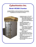
Cybortronics Inc.
Model HR2060W Chamber
The Model HR2060W is a single bay, water cooled,
temperature cycling chamber specifically designed for
the commercial electronics environment.
Specifications for the chamber are as follows:
•
•
•
•
•
•
•
•
•
•
•
Revision B1, 02/07/01
Temperature range of –10°C to +80°C
Temperature rate of change of 6°C per
minute with no live load and 50 lbs. of
Fixtured Product
60,000 BTU Refrigeration System
• Self contained within the
chamber.
• R-507 Ozone Safe Refrigerant
• Compressor Inhibit if Refrigerant
lost
40,000 BTU Heating System
1500 CFM Air Recirculation with
Vertical Airflow design
Watlow Model 981 Temperature
Controller
• 20 step Ramp & Soak profiling
• RS-232 , RS-422, or EIA 485
Communications Interface
Safety Alarms with LED Display and
Audible alert
• Over-Temperature
• Blower Failure
Front Panel Display and Control of
Alarm Status and UUT Power Control
Triple Pane Glass Doors for product
visibility
Brushed Stainless Steel and Granite
Grey Powder-Coat Exterior for
High-Tech appearance
AC Power requirements of 208 VAC, 3
Phase, 60 Amps
HR2060 Chamber Front View
Watlow
Temperature
Controller
UUT Power
Control On-Off
(Optional)
Chamber
Control
Components
under Hood
Over-temp Alarm
Reset Switch
User Cable
Pass-thru
Ports
Door `Stay’ Adjust
HR2060 Chamber Rear View
Removable access
cover for Main
Blower and
Cooling Fan
Main AC Input
Disconnect and
Circuit Breaker
Optional AC
Distribution Panel
CYB20440
With
6 Switched Outlets
and
2 User Outlets
Dehumidifier
Temperature
Controller
RS-232
Interface
Dehumidifier
Filters
( Front and Rear )
Dehumidifier
Exhaust Restrictor
Do Not Remove
Main AC Input
Connecter
Lift-Off Rear
Access Grill
208 VAC 3 Phase
60 Amps
Water Inlet
and Outlet
Connections
Condensate
Drip Pan
Compressor
Contactor
Compressor
Water Cleanout
Filter Location
Model HR2060W Chamber
User’s Guide
Section I
HR2060 Functional Description
Pg. 1
Section II
Maintenance
Pg. 8
Section III
CYB20440 AC Distribution Panel
Pg. 11
Section IV
Installation and Site Prep
Pg. 12
Section I
HR2060 Chamber Functional Description
Following is a functional description of the various elements of the HR2060
Chamber. These elements consist of the Front Panel, the Air Recirculation System,
the Heating System, the Cooling System, and the Alarm System. Please see
Figure 1.1 for a complete schematic of the electrical components of the HR2060
Chamber. All serviceable component parts with the exception of the blower and the
refrigeration components are located under the ‘hood’ of the chamber. This hood is
hinged at the top and has two knurled screws in the lower left and right corners to
allow access to the Power Control Plate, the CYB20480 Relay Module, and the
Watlow Model 146 Over-temperature Limit Control. See Figure 1.2 for the layout of
the control panel.
Front Panel The Front Panel contains the Watlow Model 981 Temperature Controller, the UUT
Power Control, and the Alarm Control . Please see Figure 1.3 for the layout of this
panel. The Watlow Temperature Controller is the ‘brains’ of the chamber, controlling
all heating and cooling functions. Output 1 (L1) of the controller is connected to the
heating circuit. Output 2 (L2) is connected to the cooling circuit. The fourth output
(L4) is the RS-232 communications interface. The L4 LED will flash whenever serial
data is being sent from the controller. An RJ-45 connector is mounted in the column
on the rear of the chamber providing the serial connection. Please see Figure 1.4 for
a quick guide to the Watlow operation. All further details of the Watlow can be found
in the Watlow ‘Series 982 User’s Manual’. Data communications interfacing and
commands can be found in the ‘Data Communications with the Watlow Series 988
Family of Controllers User’s Guide’.
The UUT Power Control consists of a switch to control the On/Off state of the AC to
the UUT outlets in the optional CYB20440 AC Distribution Panel. See Section III for
a description of this unit if this option is installed. An LED shows the status of this
switch.
The Alarm Control consists of LED’s showing the status of the Over-temp and
Blower alarms. If the associated LED is on, then an alarm condition exists.
The Audible switch allows resetting the Over-temp alarm if this alarm condition
exists.
Page 1
Air Recirculation System An 1500 CFM blower is powered continuously from 208 VAC through fuse F6. This
blower pulls air vertically up through the product, the refrigeration system’s evaporator
coil, across the heating coils, and then directs the airflow down the back wall of the
chamber. A separate 100 CFM cooling fan is attached to the blower motor.
Heating System The heating circuit is comprised of three 4000 watt nichrome heating elements
mounted just above the evaporator coil in the top of the chamber. For safety reasons,
three Solid State Relays (SSR2, SSR3, SSR4) are used to control these heating
elements. Each heater is removable and is fused at 30 amps by fuses F1, F2, and F3 .
The negative control line to all three SSR’s is the L1 output of the Watlow 981
Temperature Controller. If Output 1 (L1) is on, this terminal is grounded and will turn
on the SSR’s. The positive control line to the three SSR’s is a switched +12 VDC line.
This line will be opened by the K1 or K2 relays on the CYB20480 module if an
Over-temp or Blower alarm condition exists. All three legs of the 208 VAC input power
will then be removed upon an alarm condition.
Cooling System The cooling circuit consists of an 3.5 HP Copeland Compressor System with an associated control circuit. The system uses ozone safe R-507 refrigerant. Output 2 (L2) of
the Watlow 981 Temperature Controller, when active, will turn on the refrigeration
solenoid by grounding the negative side of SSR1. At the same time, relay SP2 on the
CYB20480 module is energized which closes the contact to the Off Delay Timer. The
timer then applies 115 VAC thru the pressure switches the 3 Phase Line Monitor to
contactor K2 to turn on the 208 VAC three phase to the compressor. Time delay fuses
(F11, F12, F13) of 15 amp capacity are used for the compressor due to the motor startup current draw. If the compressor has lost refrigerant, the pressure switches will open,
disabling contactor K2. The timer will keep the compressor running for a minimum of 3
minutes even if Output 2 has turned off. This extends the life of the compressor by assuring proper separation of the Freon and oil in the compressor. The flow of Freon is
controlled by the solenoid valve controlled by SSR1. When the Freon flow is turned off
but the compressor is still running, a ‘hot gas bypass’ valve is opened to allow the
Freon to re-circulate.
This system uses a water cooled condenser that requires 10 gallons per minute
of clean, room temperature or colder water for proper operation. Chamber cooling performance is very dependent on the flow rate and water temperature.
Page 2
Dehumidifier System A Munters dehumidifier is installed centered on the rear of the chamber. This dehumidifier is controlled by the Alarm 3 (L3) output of the Watlow and is turned on during a specific temperature range, typically between –1 and 35 deg. C. The SYS
menu on the Watlow Controller is where these programmed temperatures can be
found. Fuse F10 provides AC power to the dehumidifier and the K1 relay contact is
closed to turn on the dehumidifier via a low voltage control line. The dehumidifier
pulls in air from the chamber and blows it through a desiccant filled wheel that absorbs any moisture in the chamber. The air is then returned to the chamber. The
desiccant wheel rotates to another part of the dehumidifier where the moisture is removed by hot air being blown over it.
Alarm System The Over-temp Alarm consists of a Watlow Model 146 Limit Control that when activated, turns on relay K1 on the CYB20480 module. This in turn will close contacts to
turn on the front panel LED indicating an alarm condition and turn on the Sonalert
audible device. Another set of contacts will open the +12 VDC line controlling the
SSR’s used for the heating coils. This switched +12 VDC line is also used in the interface cable to the optional AC Distribution Panel. This will turn off the SSR’s in this
panel and remove all AC from the UUT’s, removing all heat load from the inside of
the chamber and protecting the UUT’s from damage. The Over-temp Alarm is a
latching alarm and will stay active until the problem is resolved and the alarm is
manually reset. The reset switch is a momentary rocker switch located below the
Alarm Display on the front panel. The chamber is shipped with the Over-temp Alarm
set to 75°C. Access to this control is obtained by raising the ‘hood’ of the chamber.
The Blower Alarm is an air-flow switch which when activated due to a blower failure
or slow spin condition, will turn on relay K2 on the CYB20480 module. A set of contacts will then turn on the front panel LED indicating the alarm condition along with
the Sonalert sounding. A second set of contacts performs the same functions as the
Over-temp Alarm, turning off the heaters and the AC to the UUT’s. This alarm is
self-resetting.
Page 3
1
2
3
4
5
6
F12 TRM25
Blue
CS1
8
1
A3T40
A3T40
2
60 AMPS
1
NEUTRAL
AC
AC
SSR1
SSR-40A
-
AC AC com no nc
OVERTEMP
TRM8
CONTROL
F5
80
AC
AC
AC
AC
AC
AC
SSR4
SSR-75A
SSR3
SSR-75A
SSR3
SSR-75A
-
+
-
+
-
+
RELAY
+
K3
3
F15
TRM8
4
F14
GROUND
2
3 PHASE
A3T40
3
FA
1
FB
208 VAC
4
FC
2
Solenoid
F4 AGC5
Black
3
PHASE 1
Bypass
Solenoid
Compressor
LED On When Phase OK
1
L3
A
K2
4
L2
5
2
2
L1
4
Low Side Pres.
3
MAIN
POWER
INPUT
3
CS2
Hi Side Pres.
1
Red
4KW Heater
4
PHASE 2
3 Phase
Line Monitor
4KW Heater
4KW Heater
F11 TRM25
A
8
COMPRESSOR
F13 TRM25
PHASE 3
7
AGC5
B
B
SET
P1
BLWR
15A
BLOWER
+
Load
`T'
LS1
Control Line
Plug
sw
Power Pack
-
MAIN
sw
12 VDC
TC+ TC- SW SW
F1
1
2
Off Delay Timer
SWITCH
Dehumidifier
Line
F10 AGC10
RELAY
K1
Dehumidifier AC
+
F2
15A
Distribution
Panel
F7
15A
CYB20477A
F8
To Optional AC
SONALERT
F9
11
2
3
15A
13
14
15A
16
17
J2
14
13
12
11
10
9
8
7
6
5
4
3
2
1
J1
23
RJ-45
TEMP
CONTROL
5
6
7
9
C
RS-232 to
CPU
22
WATLOW
TxD
RxD
GND
10
1
-
D2
C
`T' Type
+
2
D1
JP1
1
2
3
4
5
6
7
8
Thermocouple
3
4
6
6
4
4
6
4
8
8
8
11
11
13
13
11
13
9
9
16
1
16
K3
K1
PWR
ON
S1
5
6
PWR ON/OFF
7
AUDIBLE RESET (Mom.)
BLWR
ALM
PHZ
ALM
OT
ALM
SYS
PWR
9
16
1
K2
S2
1
FRONT PANEL
LED'S AND SWITCHES
8
CYB20480 MODULE Rev. B
On/Off Control for External Device
D
Figure 1.1
Cable on rear of Chamber
D
J3
1
2
3
4
5
6
Switched Ground
By Power On/Off Switch
Cybortronics Inc.
13845-C Alton Pkwy.
Irvine, CA 92618
1-800-289-8203
Switched +12 VDC
By Alarm Condition
Title
HR-2060 MAIN CONTROL SCHEMATIC
6 PIN MOLEX
Size
Document Number
Custom
CYB2060-SCH
Date:
1
2
3
4
5
6
7
Thursday, February 05, 2009
Rev
F
1
Sheet
8
of
1
HR Series Chamber Control Panel
( under front hood of chamber)
3 Phase Line
Monitor
Control Relay
Module
+12 VDC
Power Supply
Main AC Fuse
Block
F1 thru F10
Heater SSR’s
SSR2, SSR3, SSR4
Over-temp
Control Module
Compressor
Off Delay
Timer
Compressor
Fuses
F11, F12, F13
Spare Fuse
Block
Dehumidifier
Control
Relay
Compressor
Solenoid
SSR1
Figure 1.2
CHAMBER CONTROL PANEL
INDICATES STATUS OF
AC POWER TO POWER
SUPPLY RACK
ALARM INDICATER LED’s
IF LIT, INDICATES ALARM
CONDITION.
(BLOWER ALARM SHOWN)
67
70
INDICATES CHAMBER
+12 VDC POWER
SUPPLY IS
OPERATIONAL.
ENABLES/ DISABLES
AC POWER TO THE UUT
AC POWER PANEL OR
POWER SUPPLY RACK.
PUSH DOWN TO
RESET THE
OVER-TEMP
ALARM.
MOMENTARY
ACTION.
Figure 1.3
Watlow Controller Quick Operation Guide
RED DISPLAY
DISPLAY KEY
This display will
normally indicate the
current temperature in
the chamber. It will also
indicate the value of the
parameters displayed
in the GREEN display.
This key will cause the GREEN
display to step thru
displaying the set-point, the
deviation from set-point, the % of
output power, and wether the
temperature is displayed in °C or
in °F.
67
L1 - Indicates that the
heaters are on.
L2 - Indicates that the
cooling system is on.
L3 - Dehumidifier Control
L4 - Indicates that data is
flowing over the RS-232
port.
The 1st press of this key
will enter the SYS menu.
Use up arrow key to step to
PID menu or PROG menu.
See Watlow manual to set
PROG values and steps.
UP and DOWN ARROWS
These keys are normally used to
change the set-point of the
controller. When pressed
simultaneously for approx. 3
seconds, you will enter the setup
mode. Please see the WATLOW
MANUAL.
70
L1 thru L4 DISPLAY
MODE KEY
GREEN
DISPLAY
This display will
normally indicate the
current set-point. It
will also indicate
other functions
depending on the
use of the DISP key
and the MODE key.
Values of these
other functions are
displayed in the
RED display.
RUN / HOLD KEY
Pressing this key once will allow you to
select which of the 4 Ramp and Soak
profiles to run. The RUN Led will flash
at this time. Pressing the key again will
start the
selected profile. The RUN
Led will be on steady while a profile is
running. Ifa profile is running, pressing
this key will stop execution of that
profile and the RUN Led will be off.
Figure 1.4
Section II
Maintenance
The following items require periodic maintenance on the
Cybortronics HR2060 Chamber.
Condenser Water Cooling Line Strainer The Strainer for the water inlet line to the condenser should be cleaned on a
monthly basis. This strainer is shipped loose and should be mounted to the water
inlet line external to the chamber. Turn off water. Remove the square tipped end cap
from the strainer housing. Have a small pail available to catch any water that may
run out of the housing. Remove the strainer and wash off any foreign matter that
may have accumulated. Apply more sealing compound or Teflon tape to the end
cap, re-install the strainer, and screw on the end cap tightly. The water may now be
turned back on. Check that no water leaks from the end cap before operating the
chamber. All other refrigeration components are accessible by removing the access
grill at the rear of the refrigeration compartment. The grill hangs on two studs at the
top and is held in place by magnetic strips. Some models of chambers may also require the removal of the left side stainless panel of this compartment.
Strainer
Location
Outside of
Chamber
this side
Contactor K2
Compressor
Bypass TXV
Water
Cooled
Condenser
Drip Pan
Page 8
DEHUMIDIFIER SYSTEM FILTERS The dehumidifier filters at the front and rear ends of the dehumidifier system should
be checked and replaced as necessary every month dependent on factory conditions. These filters will slide out of their tracks with the dehumidifier still mounted to
the chamber. These filters can be disassembled, washed in water, dried and reused several times.
DEHUMIDIFIER REPLACEMENT FILTER: DF-90
Filter
Locations
Front and
Rear
Lift up to
remove
Exhaust Restrictor
Do Not Remove
BLOWER MOTOR LUBRICATION The circulation blower on the HR2040 should be oiled once a year. The oil filler
holes are located at the rear and the front faces of the motor at the 12:00 o'clock position. Using any light machine oil or automotive oil, apply only 2 drops of oil to each
bearing port.
CAUTION: ONLY US 2 DROPS OF OIL EACH SERVICE INTERVAL. TOO MUCH OIL ADDED CAN CONTAMINATE THE INTERIOR OF THE
SYSTEM AND IT'S PRODUCT
CONTENTS!
Oil hole
locations
Page 9
BLOWER REPLACEMENT INSTRUCTIONS (Complete assembly) Should the blower assembly need replacing, disconnect all
power from the chamber by removing the power cord from it's receptacle. Remove
the mounting screws for the stainless cover that houses the main disconnect On/Off
breaker. Remove and rest this cover on top of the chamber. The motor is mounted
on an 8 x 10 inch aluminum mounting plate. After removing the electrical connections from the blower terminal block, remove the 4 - #8 screws from the mounting
plate, lift and draw the motor, plate and blower wheel from the air box cover. Install
the new pre-assembled blower assembly and replace the 4 - #8 screws that secure
it. Before attaching the electrical, make certain that the blower wheel spins freely
and does not touch any surrounding metal. If the blower wheel collides with the
blower inlet ring, remove the assembly and adjust the blower wheel back toward the
motor face by 1/4 inch. Re-attach the electrical wiring to the correct terminals and
replace the stainless cover and hardware.
BLOWER COMPLETE ASSEMBLY PART NUMBER: BMA3M487
BLOWER MOTOR ONLY: 3M487
REFRIGERATION SYSTEM CHECK This is only required if the cold cycle performance seems to be slow, or if the refrigeration system does not run when cooling is commanded. The refrigeration system
is comprised of a 3.5 hp three phase, 208-230 V compressor system charged with
R507 refrigerant. The lubrication oil is a synthetic oil know as Polyol Ester Oil. At
normal operating load, the current draw by the compressor should measure approximately 8 to 13 Amps. This chamber should transition from 70°C to 0°C in approximately 6 minutes with no heat generated internally by the product under test and a
condensing water temperature of 20°C or less. Should this transition test take 50 %
longer or more under these conditions, a leak detection should be done on the system, and gas can be added as required. Each system is configured with a low and
high pressure gas switch. If no contactor is heard when the L2 lamp is lit on the controller (signifying request for cooling) and the compressor does not start, the system
should be checked for leaks. Under normal operating conditions, the high pressure
side of the system should not exceed 350 pounds. The low pressure side of the system should not exceed 80 pounds of suction. The total capacity of the HR2060 system is 10 pounds of R507. Do not overfill.
Page 10
Section III
CYB20440 AC Distribution Panel
The CYB20440 AC Distribution Panel is an option available in both 115 VAC and 208
VAC single phase versions. This panel provides six (6) Switched Outlets and two (2)
User Outlets which are on continuously. The 6 Switched Outlets are controlled by individual Solid State Relays. Each of these SSR’s are turned on or off by a connection
to the DTR signal line on the RJ-45 interfaces located below the outlets. Two RJ-45’s
are provided for each outlet such that an serial control cable may be `passed thru’ the
panel to facilitate the connection to ground and DTR for the SSR’s. An LED is also attached to each DTR line. The ground line is passed thru a relay connected to the
chamber control circuit. This relay is controlled via the Power On/Off switch located
on the front panel of the chamber. The relay will also be turned off if any alarm condition is present in the chamber. This will then disable all SSR’s and remove AC power
to any product plugged into the 6 UUT Outlets.
UUT AC
Outlet Circuit
Breaker and
Indicator
UUT AC
Power Outlets
RJ45 UUT
Power Control
Interface
Temperature
Controller
RS-232 Serial
Interface
User Outlets
and
Circuit Breaker
Page 11
Section IV
Installation and Site Prep
Power Requirements The Cybortronics Model HR2060W Chamber requires an AC input of
208 VAC, 3 Phase `Y’, at 60 Amps. Actual chamber current draw is typically 45 Amps. Proper phasing of the AC line MUST be followed for the
chamber to work properly. An 3 Phase Line Monitor will inhibit compressor operation if it detects an out of phase condition. This Line
Monitor is located under the control panel on the front of the chamber
and has an LED indicator to indicate if the AC is connected in phase or
not. This indicator must be on. If not, reversing 2 of the 3 phase line will
usually correct the problem. If the chamber is to be connected directly
to a Junction box and not using the provided plug, the following is the
color code of the line cord attached to the chamber:
Phase 1 Phase 2 Phase 3
Neutral Ground -
Black
Red
Orange
White
Green
Water Requirements The chamber requires clean water provided at a flow rate of at least
10 gallons per minute. A throttle valve will regulate the flow rate as the
chamber is going cold. Proper performance depends on this water being 20°C or colder. The ramp rate of the chamber going cold will be determined by this water temperature.
Dimensions and Electrical /Water Connection
Locations The following 3 pages show all chamber dimensions, electrical and
water connection locations.
Page 12
HR2060 Chamber Dimensions
Front View
8 5. 7 5 "
61. 00"
I nt er i or
6 8. 5 0 "
24 . 0 0"
I nt er i or
2 8 . 30 "
Page 13
HR2060 Chamber Dimensions
Side View
Deh umi di f i e r
HBL 56 0P9W
85. 75"
2 08 VAC
3 0 ` Y'
6 0 amps
Wa t e r
Fi t t i n g s
o n Re a r
68. 50"
1 I nc h
NPT
33. 75"
47. 50"
Page 14
HR2060 Chamber Dimensions
Footprint
Wa t er
Co n ne c t i on s
1 I n c h NPT
4 7. 5 0 "
Fr o n t
Do o r
28. 30"
Page 15