1
OPERATING INSTRUCTIONS
DIVERSITY WIRELESS TUNER
WT-870
Please follow the instructions in this manual to obtain the optimum results from this unit.
We also recommend that you keep this manual handy for future reference.
TOA Corporation
GENERAL DESCRIPTION
Designed for virtual elimination of problem "null spots" or "dropouts" (momentary loss of radio signal
reception), the TOA WT-870 is a diversity tuner that permits simultaneous use of up to two optional
wireless tuner modules WTU-870 and WTU-871. To ensure its reliability, the WT-870 employs a
compressor/expander system noise reduction circuit to minimize the influence of high-frequency noise
generated from digital equipment such as personal computers and word processors as well as a
combined noise/tone squelch circuit.
HANDLING PRECAUTIONS
Check for proper operating voltage of your tuner before use.
The model WT-870 "L" is intended for operation on 120V AC/60 Hz, and the WT-870 "H" for
220-240V AC/50 Hz.
When using a component rack, avoid installing the unit above heat generating equipment, such as a
power amplifier.
To avoid severe electrical shocks and possible catastrophic damage, never open the unit nor touch
its internal components.
To clean the unit's exterior, wipe with a soft dry cloth. Never use benzine, thinner, or other solvents,
which may damage the painted parts of the unit.
FEATURES
Diversity reception system minimizes the effects of fading during reception of a radio signal.
A tone squelch prevents disturbing radio signals from producing noise when the wireless microphone
is not in use.
Modular construction facilities channel expansion and frequency changes.
Space-saving design and simultaneous dual channel operation.
Rack mountable. (Optional brackets required.)
Wide dynamic range and less susceptibility to high frequency noise in space thanks to a
compressor/expander circuit.
–2–
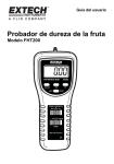
NOMENCLATURE
[Front Panel]
Power Switch
Reception Indicator
Press this switch to turn power on. To turn power
off, press this switch again. Power Indicator lights
when the power is switched on.
The left lamp lights when antenna A receives a
signal. The right lamp lights when antenna B
receives a signal.
Power Indicator
Level Indicator
Tuner Receptacle
Lights in proportion to the intensity of input into a
wireless microphone.
Insert an optional tuner module WTU-870 or WTU-
871.
Frequency Label
Volume Control
Attach the label (supplied with the WTU-870 and
WTU-871)to the unit.
Adjusts the output volume.
Blank Panel
[Rear Panel]
Antenna Connector
Mixing Output Level Selector
(BNC, 75 , Phantom Power Ouptut: 9V DC)
Connects to an optional wireless antenna, and
supplies DC power to the YW-620 having a built-in
booster amplifier.
Switches mixing output levels.
Audio Output XLR Connector
(–60 dBV, Output Impedance : 600 , Balanced)
Provides individual outputs of built-in tuner
modules.
Mixing Output
Line Output : 0 dBV, Output Impedance : 10k ,
Unbalanced
Mic Output:–60 dBV, output impedance : 600 ,
unbalanced.
Mixes built-in tuner module outputs.
–3–
Line Output : Connects to the line (AUX) input
terminal of connected component.
Mic Output : Connects to the mic input terminal of
connected component.
DC IN (12V DC)
Power input terminal for external DC power supply.
AC Inlet (3 pins)
Power input terminal for AC power supply. Use the
supplied power cord.
TUNER MODULE INSTALLATION AND REPLACEMENT
CAUTION
These servicing instructions are for use by qualified personnel only. To avoid electric shock do
not perform any servicing other than that contained in the Operating Instructions unless you
are qualified to do so. Refer all servicing to qualified service personnel.
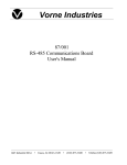
1. New Installation
(1) Press the stopper of the tuner
panel with a screw driver.
(3) Open the tuner panel.
(4) Insert a tuner module,
(2) Pull the tuner panel towards
you while pressing the stopper.
D1234
(5) After checking to confirm the
tight connection of the tuner
panel connector, fit the tuner
panel in place.
(6) Attach the frequency label
supplied with the tuner module
to the assigned space.
After the frequency label has
been attached, make sure to
attach a color identification
label on it.
Color Identification Label
Attach one of the supplied labels of different colors to the tuner's panel. (Both the tuner and its
corresponding hand-held microphone have to be marked with the same color for easy association
with their frequencies.)
2. Installation (Expansion)
The tuner module WTU-870 or WTU-871 and the tuner panel WP-860 are required.
(1) Remove the blank panel of the unit.
(2) Attach the unit's connector to the tuner panel connector.
(3) Insert a tuner module (WTU-870 or WTU-871)
(4) Fit the tuner panel in place.
(5) Attach the frequency label supplied with the tuner module.
3. Replacement
Pull out the tuner module with long nose radio pliers.
[Note] Be sure to refer the installation and replacement to qualified service personnel.
–4–
OPERATIONS
(3) Adjust the volume control of the module of which reception indicator lights.
(2) Set the wireless microphone's power switch to ON. The (1) Switch the power on.
corresponding module's reception indicator lights. Out
The power indicator lights.
of two reception indicators for antenna A and B, one
corresponding to the antenna receiving the strongest
radio signal lights.
Note on level indicator
The level indicator lights depending on the intensity of input into the wireless microphone, regardless of the
volume control setting. When the indicator lights red frequently, your voice can be distorted at a microphone
circuit. In such cases, move your mouth away from the microphone so that the indicator lights yellow at a
maximum level. This is not needed if the indicator lights red only occasionally.
If the microphone is equipped with a sensitivity control, adjust the control so that the level indicator lights yellow
when spoken loud.
CONNECTIONS
When using with the mixing console, connect the output of WT-870 to XLR-type input connectors of
the the mixing console.
Wall-mount dipole
wireless antenna
YW-620
Mobile wireless Whip wireless
antenna
antenna
YW-610
YW-600
Wall-mount dipole Mobile wireless Whip wireless
antenna
wireless antenna antenna
YW-620
YW-600
YW-610
YW-600 : Direct mount type to the tuner. Requires no antenna cable.
YW-610 : Mobile type antenna. Antenna cable must be under 10m (33 feet)
in length.
YW-620 : Fixed mount type antenna having a built-in booster amplifier.
Wireless microphones can be used in wide ranges.
AC IN
E
DC IN Connector
COLD
HOT
Mixer, etc.
–5–
INSTALLATION PRECAUTIONS
Install the tuner, antennas, and antenna cable away from high frequency noise generating
equipment, such as fluorescent lamps and personal computers, whenever possible.
Avoid installing receiving antennas in close proximity to metal stuff, such as steel frames and
lockers. Install receiving antennas at least 30cm (1 foot) away from the wall.
The distance between two antennas must be over 3m (10 feet). If both are installed in the same
location, the diversity reception is not effective.
Coaxial cable's high frequency loss increases as frequencies become higher. Keep the connection
cable between antenna and tuner as short as possible.
Maximum Antenna Cable Length
Cable type
External diameter
RG-59/U
6.1 mm (0.24")
RG-6U
7.4 mm (0.29")
Max. length
(when YW-620 is used.)
48m (160ft.)
48~70m (160-230 ft. )
RACK MOUNTING
Optional mounting kit is required for rack mounting. Remove rubber supporters from the equipment.
1. Mounting one unit in a rack. (Optional mounting kits MB-14 and BK-014B are to be used.)
2. Mounting two units in a rack. (Optional mounting kits MB-14 and J-700 are to be used.)
3X16 tapping screw
WT-870
WT-870
3 X 1 6 tapping screw
(Supplied with the MB-14)
MB-14
Flat head screw (M3X6)
included in J-700
J-700
Fiber washer (Supplied with the MB-14)
Mounting screw (Supplied with the MB-14)
–6–
ADDITIONAL EXPLANATIONS
1. Diversity Reception
Conventional single-antenna system receivers have often produced "null spots" where a radio signal
is suddenly lost during its reception. The diversity reception method enables stable signal reception all
the time.
2. Squelch Circuit
In a receiver employing only a noise or carrier squelch, the squelch circuit is actuated and provides
the output whenever the receiver receives the same RF carrier as a receiving frequency. This causes
even a disturbing radio signal to be received provided its frequency is the same as the receiving
frequency. As a result, it can happen that sound is suddenly heard from the speaker due to disturbing
radio signal even when the wireless microphone's power switch is left OFF.
The squelch circuit of TOA's wireless systems consists of both the tone and noise squelches, and is
not actuated if only same RF carrier as the receiving frequency is received. It is so designed as to be
actuated and output a signal only when the received RF carrier contains a very exact pre-determined
tone frequency component. Therefore, disturbing radio signals are rejected and the speaker can be
kept completely quiet when the wireless microphone's power switch is set to OFF, ensuring reliable
use in every application.
3. Frequency Indicators
Component frequency ratings are expressed in combinations of alphabetic and numeric characters,
with letters substituted for all numbers to the left of the 1 MHz digit.
For example:
C = 160 MHz
F = 190 MHz
D = 170 MHz
G = 200 MHz
E = 180 MHz
H = 210 MHz
All numbers to the right of the 10 MHz digit are still expressed as numerals.
Therefore : D5432 = 175.432 MHz
G7654 = 207.654 MHz
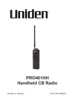
BLOCK DIAGRAM
VR 1
DISTRIBUTER 1
CH 1 OUTPUT
–60 dBV, 600
BALANCED
(XLR TYPE)
TUNER 1
ANT. IN
1
CH 2 OUTPUT
–60 dBV, 600
BALANCED
(XLR TYPE)
TUNER 2
VR 2
ANT. IN
2
0 dBV, 10k
MIXED
OUTPUT
(Phone Jack)
DISTRIBUTER 2
ATT.
–7–
– 60 dBV, 600
SPECIFICATIONS
WT-870
Power Requirements
120V AC, 60 Hz ("L" version)
220~240V AC, 50 Hz ("H" version)
Power Consumption
DC Input
Antenna Input
Audio Output
Mixing Output
Operating Temperature
Dimensions
Weight
Finish
10W (when 2 WTU-870's or WTU-871's are mounted)
12-18V DC, 400mA max.
75
, BNC
Power supplied to antenna : 9V DC, 30mA max.
–60 dBV, 600 , balanced
LINE : 0 dBV, 10k , unbalanced
MIC : –60 dBV, 600 , unbalanced
–10°C~50°C (14°F~122°F)
210X47.5X280mm (8.3"X1.9"X1.0")
Approx. 2.3kg (5.07lb.)
Panel: black
Module and blank panel: resin (black)
WT-870 equipped with WTU-870 or WTU-871
Receiving Frequency
169.445 MHz~171.905 MHz (FCC Part 90/USA)
174.250 MHz~215.250 MHz (FCC Part 74/USA,D.O.C/CANADA)
173.8 MHz~175.0 MHz (MPT1345/UK)
202.1 MHz~203.7 MHz (DOC 60/AUSTRALIA)
Receiving Sensitivity
Squelch Sensitivity
Frequency Response
Residual Noise
Under 20 dBµ V(S/N : 75 dB/Deviation : 15 kHz)
(S/N : 80 dB/Deviation : 40 kHz)
Approx. 14 dB µ V
100 Hz~12kHz±2dB
Less than 30 µ V (8 µ V : A -weight)
Overall System Performance (WT-870, WTU-870/WTU-871, WM-280/WM-281/
WM-290/WM-291)
Transmission Distance
Dynamic Range (SNR)
30~100m (100~330 feet)
Distortion
Under 1 %
Better than 90 dB (102 dB : A-weight)(60 dB µ V, 15 kHz Deviation)
Better than 95 dB (102 dB : A-weight)(60 dB µ V, 40 kHz Deviation)
*Specifications are subject to change without notice.
Accessories
Power cable .......................... 1
DC input connector...............1
Color identification labels.......1
Operating instructions........... 1
Warranty card ....................... 1 (only "L" version)
TOA Corporation
KOBE, JAPAN
133-07-074-90