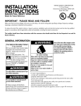
1
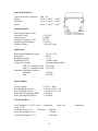
SERVICE NOTEBOOK
VCWB300 PROFESSONAL MODEL
BUILT-IN FULL HEIGHT WINE COOLER
Table of Contents
Technical Information--------------------------------------------------------------------- 4
Sealed System------------------------------------------------------------------------------ 5
Control Panel Assembly------------------------------------------------------------------- 6
Mode of Operation------------------------------------------------------------------------ 6
Temperature Readout and Setting----------------------------------------------- 7
Display Off------------------------------------------------------------------------- 7
Compressor Protection------------------------------------------------------------ 7
Fan Operation---------------------------------------------------------------------- 7
Alarm Security--------------------------------------------------------------------- 8
Holiday Mode---------------------------------------------------------------------- 8
Service Mode----------------------------------------------------------------------- 8
Display Interface Board----------------------------------------------------------- 8
Glass Mullion Shelf---------------------------------------------------------------- 9
Electronic Function Description-------------------------------------------------------- 10
Display Panel Keyboard---------------------------------------------------------- 10
Power Disconnect Switch--------------------------------------------------------- 10
Showroom Switch----------------------------------------------------------------- 10
Display Panel Operation----------------------------------------------------------------- 11
Keyboard Entry Tone------------------------------------------------------------- 11
Zone Pad---------------------------------------------------------------------------- 11
Lower Temp Pad------------------------------------------------------------------- 11
Higher Temp Pad------------------------------------------------------------------ 11
Lights-------------------------------------------------------------------------------- 11
Display Pad------------------------------------------------------------------------- 12
Alarm-------------------------------------------------------------------------------- 12
Wine Cooler Leveling---------------------------------------------------------------------- 12
Door Stop Adjustment---------------------------------------------------------------------- 13
Hinge Adjustment--------------------------------------------------------------------------- 13
Diagnostic Check Points------------------------------------------------------------------ 14
E1 – Display Board Output------------------------------------------------------- 14
E2 – Touch Switch Inputs-------------------------------------------------------- 14
E3 – Outputs and Line Voltage Inputs------------------------------------------ 14
E4 – Thermistor Inputs------------------------------------------------------------ 15
Compressor Relay------------------------------------------------------------------ 15
Alarm Wires------------------------------------------------------------------------- 15
Display Board----------------------------------------------------------------------- 15
Compressor (General Information)-------------------------------------------------------- 16
Thermister Resistance Reading------------------------------------------------------------- 17
Solenoid Valve / Evaporator Fan----------------------------------------------------------- 18
Wiring Schematic---------------------------------------------------------------------------- 19
Wiring Diagram------------------------------------------------------------------------------ 20
3
VCWB300
DDWB300 DESIGNER – DFWB300 FULL OVERLAY
BUILT-IN FULL HEIGHT WINE COOLER
VIKING TECHNICAL INFORMATION
*
DUE TO POSSIBLITY OF PERSONAL INJURY OR PROPERTY DAMAGE, ALWAYS
CONTACT AN AUTHORIZED TECHNICIAN FOR SERVICING OR REPAIR OF THIS WINE
COOLER.
The Viking Built-in Full Height 30” W. wine cooler (VCWB series) is designed to meet
the needs of the upscale wine connoisseur while also meeting Viking Range
Corporation’s stringent product standards. The product is 30” (76.2cm) wide and 84”
(213.4cm) tall. The product has adjustable leveling legs to allow the height to be
adjusted from 82 1/2” TO 84 3/4” (209.6 to2120.7cm). The sealed system is located on
the top of the product.
The product has commercial type construction and is available with various features and
color options.
General Specifications
Model
Internal Volume Capacity
Electrical Requirements
Maximum Amp Usage
Refrigerant Type
Refrigerant Charge
Overall Width
Overall Depth without Handle
Includes Door Extrusions
(Designer DDWB300)
(Full Overlay DFWB300)
Overall Height (Rollers to Top
of Air Grille)
VCWB300#
150 Bottles
115VAC, 60 HZ and 15 Amps
2.0 Amps
HFC – 134a
See Rating Label
30 inches (76.2cm)
24”
24 ½”
24 ¾” to Front of Grille
82 ½” to 83 ¾”
4
SEALED SYSTEM
The sealed system consists of the following components (listed in order of refrigerant
flow):
1 condenser coil
1 dryer assembly
3 solenoid valves
3 heat exchangers
3 evaporators
1 compressor
1 discharge tube
1 drain pan heater
1 pre-condenser loop
Refrigerant Type – HFC 134a
Refrigerant Charge – 7.3 oz.
Evaporator Temperature Range
14°F to - 31°F
Expanding Device – Cap tube
Compressor Cooling:
LBP 32° C Ambient temp 98 to 140V
LBP 43° C Ambient temp 98 to 140V
Maximum Condensing Pressures:
Operating
230 psig
Peak
293 psig
Electrical Data:
Normal Voltage 115VAC / 60Hz
Start Winding Resistance – 21.20Ω (at
77°F) ± 8%.
Run Winding Resistance – 7.90Ω (at
77°F) ± 8%.
Locked Rotor Amps (60Hz) – 9.80
Amps.
Full Load Amps (60Hz) – 1.20 Amps.
5
CONTROL PANEL ASSEMBLY
The wine cooler is equipped
with
a
control
panel
conveniently located in the top
front of the top compartment
of the wine cooler. From this
point the user can operate all
functions of the wine cooler’s
temperature management and
various electronic features.
The control panel housing is
constructed of injected molded
plastic. A glass keyboard is
fastened to the housing by
means of snap clips that are
incorporated into the molded
housing. The keyboard is then
secured in place with an
adhesive. The keypad utilizes
a special technology that
senses mass. When the user
places a finger on the glass
surface at designated “button”
locations
the
control
recognizes this and converts
this to an electronic signal.
This signal is then processed by the wine cooler’s control that promptly results in a
change of temperature settings or some of the other wine cooler electronic features.
On the underside of the control panel a means for attaching two light bulbs is molded in
place. The light tubes are installed into a separate lamp holder, which is then attached to
the control panel by four “molded in” clips and four screws.
Mode of operation: Microprocessor based 3 – channel temperature / logic control.
Normal cooling operation: Control will independently read and regulate the average
temperatures of each chamber to its corresponding set point as shown on the vacuum
florescent display (“VFD”). When cooling is called for, the zone valve will energize and
the compressor will energize 60 seconds later. Only one zone valve / fan can be
energized at a time. Chamber 1 will take precedence over chamber 2, which will take
precedence over chamber 3 in the event that more than one chamber is calling for cooling
at the same time. Each chamber will run for a maximum of 10 minutes after which it will
switch to the next chamber requiring cooling. When a chamber reaches 1º below set
temperature the zone valve is de-energized. The control will energize the compressor
6
and appropriate zone valve based upon the temperature at the evaporator thermistor and
will turn off the zone valve based upon the temperature at the chamber thermistor.
Temperature readout and setting: Pressing the zone button will change which chamber
is selected for adjustments. The selected chamber will have a bar displayed over the
temperature reading on the VFD. Pressing the higher or lower buttons will raise or lower
the set point of the selected chamber in one degree F increments. Every time any set
point is changed a “set time” delay will start. When the “set time” delay is completed
without another change in the temperature the currently displayed number will become
the new set point. The new set point will be stored in non-volatile memory. The unit will
begin controlling the particular chamber to the new set point, and the actual chamber
temperature will be displayed. Temperature can be displayed in either Degrees F
(default) or in Degrees C. It can be changed from one to the other by pressing and
holding both the display on/off and the display alarm buttons simultaneously for 5
seconds. The display will show “F” or “C” appropriately. This setting will be stored in
non-volatile memory and will be saved during period of power loss.
Display off: To turn the display off, momentarily press the display. The display will turn
off as soon as the button is released.
To turn the display on, momentarily press the display button. The display will turn on as
soon as the button is released.
Compressor protection: At any time the compressor needs to start, including that power
up the appropriate zone valve will energize for 60 seconds before the compressor is
allowed to start. This is intended to allow to discharge any pressures in the system so that
the compressor will not start under heavy load. Any time that all chambers reach set
temperatures(s), the compressor will continue to run for an additional 30 seconds. This is
intended to reduce compressor start / stop cycles as the various chambers call for cooling.
Fan operation: The evaporator fans, if running will shut off whenever the door switch
opens and turns back on when the door switch closes. When operating in Holiday Mode
the Fan(s) will not turn off, if running, when the door switch opens.
Chamber lighting: The light inside the chambers can be always on, or only on when the
door switch is open. Pressing the lights button on the front panel toggles this setting.
Also see holiday mode.
Alarm security: Alarm operation can be toggled on or off by pressing the alarm front
panel button for 2 seconds. When the temperature inside any chamber is higher than the
set temperature by more than 5 degrees F for longer than the “2 hours” delay, the display
will flash on and off and an audible signal will sound. When the alarm mode is active, an
enunciator will appear in the display. Upon initial power-up, the alarm will be disabled
for a start-up delay to allow for the unit to reach temperature. The alarm can be disabled
by pressing the alarm off button. A door alarm is provided that will sound if the door
switch is open for longer than the door alarm delay. The alarm will shut off upon reclosing the door and the delay time will be reset. Temperature alarm operation will be
inhibited in show room mode. Home security contacts will transfer during an alarm
condition. When operating in Holiday Mode, the high temperature alarm and door
alarms are disabled.
7
Showroom mode: This mode, selected by closing the showroom switch is intended to simulate
normal operation in all ways except the cooling and temperature alarm functions. Closure of this
switch will over-ride normal cooling. Temperature displayed for the chambers will be the last
temperatures stored in memory, or the factory defaults setting if they have not been changed.
Lights and functions will occur as in normal cooling operation described above.
Holiday mode (Sabbath mode): Pressing and holding the display button continuously for 10
seconds accesses this mode. (Note: The Display must be “on” before entering Holiday Mode.)
To cancel Holiday Mode, press and hold the display button continuously for 10 seconds. When
Holiday Mode is selected, a random time delay of 15 to 25 seconds will be applied to the
compressor relay start and stop. The chamber lights relay will remain de-energized. The display
will not be illuminated. Audible sound (beep) from the control will be disabled. Fan outputs will
not be affected by opening or closing of the door switch. All front panel buttons will be
inoperative except a 10 second press of the display button causing the control to exit Holiday
Mode. All other functions will continue as in normal cooling described above. The Alarm
sounds is disabled and the home security relay will not transfer.
Service mode: This mode, selected by pressing and holding zone, higher temp and lights buttons
simultaneously for 5 seconds is intended for manual operation of the compressor, valves and fans
for purposed of servicing / diagnosing and repair. When put in to this mode, valve 1 will energize
for 10 seconds to relieve any pressures in the system. The compressor will then energize and
continue to run continuously while in service mode. Pressing the zone button will change which
chamber is active as indicated on the display. The solenoid valve and evaporator fan will
energize in the chamber that is active. To leave the service mode, press and hold the zone higher
temperature and lights buttons simultaneously for 5 seconds, normal operation will then resume.
Charge mode: Pressing the lower temp button while in service mode selects charge mode. In
this mode all zone valves are open and all other functions are “off”. This is to vacuum, evacuate
and charge the sealed system. To exit charge mode the power must be removed, turn “off” the
power switch or unplug the product.
Display interface board: Mode of operation: Interface board for Vacuum fluorescent display
module.
During normal operation, temperatures in all three chambers are displayed and the red lens is
blinking approximately once per second when the RS-232 signal is being received. A “bar”
symbol is displayed over the “active” temperature reading. The “adjusted” temperature will be
displayed as blinking, approximately .5 seconds on .5 seconds off.
When the “alarm mode enabled” signal is being received the “alarm” symbol will be displayed.
If the “alarm” signal is being received, the “alarm” word will be displayed for approximately 4
seconds and the chamber temperature will be displayed for the next 4 seconds. The piezoelectric
sounder will turn on for 100 milliseconds, approximately every 8 seconds. The display will be
on, even if the “display blank” command is being received.
8
GLASS MULLION SHELF
Each compartment is separated be a fixed glass shelf (“Mullion” – two per wine cooler).
These glass shelves are uniquely designed such that they act not only as an insulated
divider wall, but also provides a means of draining the condensate water from the top and
middle compartments and as a means of attaching and supporting the light tubes for the
middle compartment.
The bottom trim of the shelf has holes for mounting the assembly to the cabinet of the
wine cooler. This is accomplished through the use of “L” brackets that are attached to
the liner walls of the cabinet and then attached to the shelf at an angle of 90° with respect
to the walls of the wine cooler. Two of these “L” brackets are used: one on each side.
The condensate drain nozzle is tapered so that a drain tube can be interference free onto
the outer diameter of the nozzle. The drain tube directs condensate water to a desired
location. For the top compartment, the tube directs water to the middle compartments
mullion drain sump. For the middle compartment, the drain tube directs water to the
sump in the liner bottom.
Each mullion shelf has
two “flanges” and two
screw bosses located at
the front bottom of the
device. The two light
tubes for the middle
compartment are snapped
into the flanges at each
end and are then secured
in place at each end with
a screw and a light tube
clamp. The wires for the
light tubes are then routed
along the left side of the
shelf and secured and
covered with an extruded
wire channel.
9
DISPLAY PANEL KEYBOARD
ELECTRONIC FUNCTION DESCRIPTION
Power Disconnect Switch:
The power on/off switch is used to turn the power off to the wine cooler when cleaning it
or changing the light tubes. The wine cooler is shipped with the power on/off switch in
the on position. To turn the power off, remove the center grille assembly by grasping the
three center louvers, lifting up and pulling outward. Press the power on/off switch to the
“ON” position. Replace the center grille assembly by aligning the hooks in the assembly
with the slots in the brackets which are attached to the grille. Push in over the hooks and
slide grille assembly downward.
Showroom Switch:
The showroom switch
allows
electronic
controls and interior
lights to function
independently of the
refrigeration system.
Your wine cooler is
shipped with the
showroom switch in
the “OFF” position.
To use the showroom
mode, remove center
grille assembly and
turn the showroom
switch to the “ON”
position. Showroom
mode
will
be
engaged.
10
DISPLAY PANEL OPERATION
Keyboard Entry Tone
Zone Pad
Indicates a pad was pressed, command read and accept.
1. Toggle between zones for set point temperature adjustment.
Pressing immediately toggles from Top to mid to bottom,
respectively that order. Entry tone will sound at each depression
of pad.
2. Used in conjunction with “Higher Temp” and “Lights” pads to
enter service mode. Press “Zone”, “Higher Temp” and “Lights”
simultaneously for 5 seconds to activate service mode.
3. Used in conjunction with “Higher Temp” and “Lights” pads to
exit service mode. Press “Zone”, and “Lights” simultaneously
for 5 seconds to exit service mode. Normal operation will then
resume.
4. In service mode toggles between zones. Pressing immediately
toggles from Top to mid to bottom respectively that order.
Lower Temp Pad 1. Lowers Temperature settings in 1 degree increments. Entry tone
will sound at each depression of pad until desired temperature
setting is achieved.
2. Activates charge mode – Press lower temp pad when in “service
mode” to activate charge mode.
Higher Temp Pad Raises temperature settings in 1 degree increments. Entry tone will
sound at each depression of pad until desired temperature setting is
achieved.
1. Used in conjunction with “Zone” and “Lights” pads to enter
service mode. Press “Zone”, Higher Temp” and “Lights”
simultaneously for 5 seconds to activate service mode.
2. Used in conjunction with “Zone” and “Lights” pad to exit service
mode.
Press “Zone”, “Higher Temp” and “Lights”
simultaneously for 5 second to exit service mode. Normal
operation will then resume.
Lights
Toggle between lights on when door open only and lights always on.
Warning: May affect temp regulation of Wine Cooler. Entry tone
will sound at each depression of pad.
1. Used in conjunction with “Zone” and “Higher Temp” pads
to enter service mode. Press “Zone”, Higher Temp” and
“Lights” simultaneously for 5 seconds to activate service mode.
2. Used in conjunction with “Zone” and “Higher Temp” pads to
exit service mode. Press “Zone”, “Higher Temp” and “Lights”
simultaneously for 5 seconds to exit service mode. Normal
operation will then resume.
11
Display Pad
1. Activates control panel. Pressing button for 2 seconds
toggles the display on/off. Entry tone will sound at after 2
seconds of pad depression.
2. Activates Holiday Mode. Pressing button for 15 seconds
toggles the holiday mode on/off.
3. Used in conjunction with “alarm” pad to toggle between
“F” Fahrenheit and “C” Celsius temperature reading. Press
and hold “Alarm” and “Display simultaneously for 10
seconds to change from one to the other (“F” or “C”)
4. Used in conjunction with “Alarm” button, temperature can
be displayed in either Deg F (default) or in Deg C. It can
be changed from one to the other by pressing and holding
both the “Display” and the “Alarm” buttons simultaneously
for 5 seconds. The display will show “F” or “C”.
Alarm
Toggles between alarm on and off. By pressing the alarm pad
for 2 seconds.
1. Activates alarm feature.
2. Deactivates alarm feature.
3. Disables alarm in the event of a high temperature condition.
4. Used in conjunction with “Display” button temperature can
be displayed in either Deg F or in Deg C. It can be
changed from one to the other by pressing and holding both
the “Display” and the “Alarm” buttons simultaneously for 5
seconds. The display will show “F” or “C”.
Wine Cooler Leveling:
A. Lift the wine cooler off the rollers, adjust to
the desired height and level wine cooler by
using a 5/16” hex head wrench. (Refer to
Figure at the right).
1. To raise right side rear, rotate the right side
rear hex rod Clockwise.
2. To raise the left side rear, rotate the left side
rear hex rod Clockwise.
3. To raise the right side front, rotate the right
side front hex rod Clockwise.
4. To raise the left side front, rotate the left side
front rod Clockwise.
NOTE: DO NOT use an electric driving device. Over tightening can cause damage.
B. Align wine cooler with sides of cabinets by adjusting leveling legs. Rotate leveling
legs until firmly in place against floor.
C. To secure wine cooler, raise until compartment cover is firmly seated under the soffit
or anti-tip boards.
12
LEVELING ADJUSTMENTS
DOOR STOP ADJUSTMENT
1.
2.
Using a 3/16” allen wrench, remove door stop pin located in bottom hinge.
The pin is factory set 110°. For 120° swing, move the pin to the utmost forward
stop hole. For 90° swing, move the pin to the utmost rear stop hole.
HINGE ADJUSTMENT
1.
2.
3.
Using 3/16” allen wrench, remove the door stop
pin located in bottom hinge.
Using the height adjustment shim as a wrenching
device, rotate the height adjustment bushing
counterclockwise to raise or clockwise to lower
the location of the door.
When proper adjustment is reached, align shim
with door stop pin holes and replace door stop
pin. Firmly tighten pin in place.
13
DIAGNOSTIC CHECK POINTS
(Rfer to Wiring Schematic on Page 19)
Number
DescriptionA
E1
1
2
3
Display Board Send
+5Vdc
data signals
ground
1
2
3
4
5
6
7
8
9
10
11
12
Touch switch inputs (with switches connected), typical
+5VDC
Ground Common for measurements on E2
Not connected
When button is touched +4Vdc to +5Vdc, otherwise less than +1Vdc.
When button is touched +4Vdc to +5Vdc, otherwise less than +1Vdc.
When button is touched +4Vdc to +5Vdc, otherwise less than +1Vdc.
+5Vdc
Ground Common for measurements on E2.
Not connected.
When button is touched +4Vdc to +5Vdc, otherwise less than +1Vdc.
When button is touched +4Vdc to +5Vdc, otherwise less than +1Vdc.
When button is touched +4Vdc to +5Vdc, otherwise less than +1Vdc.
E2
E3
1
2–7
8
9
10
11
12
13
14
15
16
Outputs and line voltage inputs (loads connected) typical.
Showroom switch off = 0V, on = 120VAC
Not connected.
Door switch open = 0V, closed = 120VAC.
When Zone* is being cooled or service mode = 115 VAC , off = 0V
When Zone* is being cooled or service mode = 115 VAC , off = 0V
When Zone* is being cooled or service mode = 115 VAC , off = 0V
When zone** is being cooled or service mode = 115 VAC , off = 0V
When zone** is being cooled or service mode = 115 VAC , off = 0V
When zone** is being cooled or service mode = 115 VAC , off = 0V
When zone* lights to be on = 115 VAC , off = 0V
Power line neutral. Common for all E3 measurements.
* E3 pin 9 Solenoid #1 / pin 10 Solenoid #2 / pin 11 Solenoid #3
** E3 pin 12 Evap. Fan #1 / pin 13 Evap. Fan #2 / pin 12 Evap. Fan #3.
NOTE: All wiring controlling Fan #3, Sol #3, and both #3 Thermisters have Black strips.
All wiring controlling Fan #2, Sol #2 and both #2 Thermisters have Red strips.
All wiring controlling Fan #1, Sol #1 and both #1 Thermisters have White strips.
14
DIAGNOSTIC CHECK POINTS (con’t)
E4
Thermister inputs (measured with thermisters disconnected).
1 to 8
3 to 4.5 VDC – TE2 (Evaporator Thermister #2)
2 to 9
3 to 4.5 VDC – TC1 (Compartment Thermister #1)
3 to 10
3 to 4.5 VDC – TE1 (Evaporator Thermister #1)
4 to 11
3 to 4.5 VDC – TC3 (Compartment Thermister #3)
5 to 12
3 to 4.5 VDC – TE3 (Evaporator Thermister #3)
6 to 13
3 to 4.5 VDC – TC2 (Compartment Thermister #2)
7 to 14
3 to 4.5 VDC
Compressor Relay
(use E3 – 16 as common for measurements)
Com
115 VAC continuous (power line supply).
NO
115 VAC when compressor is running.
NC
Not connected.
Alarm wires
Black
Red
White
(check for continuity – these are contact closures only)
Common
Normally closed (in no – alarm condition)
Normally open (in no – alarm condition)
Display Board
(IDB5D –4330)
E1
Display Board receive
1
+5VDC
2
data signals
3
ground
E2
Futaba VFD display data connection
TE = Thermister / Evaporator -- Cut-in (39°F minimum) for Evaporator Temperature
TC = Thermister / Compartment – Compartment cut-out Temperature.
Thermister Tolerance ± 2 degrees.
15
General Information:
Approved Board Certification
Suction
Discharge
Process
CSA – UL
0.256” + 0.005” / - 0.003”
0.194” + 0.003” / - 0.003”
0.256” + 0.005” / - 0.003”
Mechanical Data:
Low Starting Torque (LST)
Lubricant Charge
Lubricant type
Lubricant Viscosity @ 40° C
Weight (with Oil Charge)
Nitrogen Charge
6.76 fl. Oz.
ESTER
ISO 22
15.43 lbs.
2.84 to 4.27 psig.
Application:
Evaporating Temperature range
Refrigerant
Refrigerant Charge
Expanding Device
Compressor Cooling
LBP 32° C Ambient Temp.
LBP 43° C Ambient Temp
Maximum Condensing Pressures
Operating
Peak
14°F to -31°F
R134a
7.5 oz.
Capillary Tube
Operating Range (60Hz)
98 to 140V
98 to 140V
230 psig.
293 psig.
Electrical Data:
Normal Voltage
Start Winding Resistance
Run Winding Resistance
Locked Rotor Amperage (60Hz)
Full Load Amperage (60Hz)
115VAC – 60Hz
21.20 Ω (at 77°F) ± 8%
7.90 Ω (at 77°F) ± 8%
9.80 Amps.
1.20 Amps
Check Point Data:
Test Conditions: @115V - 60Hz (Evaporator
Temp.-10°F
Temp.130°F)
Cooling Capacity ± 5%
275 Btu/h
81 Watts
Power Consumption ± 5%
75 Watts
Current Consumption ± 5%
0.98 Amps
16
/
Condensing
THERMISTER RESISTANCE READING
Using a Cup of Water (full of ice) at 32°F , place the Thermister in the water and
you should read approximately 7353 Ω’s.
DEG. F
25
26
27
28
29
30
31
32
33
34
35
36
37
38
39
40
41
42
43
44
45
46
47
48
49
50
51
52
53
54
55
56
57
58
59
60
61
62
DEG. F
63
64
65
66
67
68
69
70
71
72
73
74
75
76
77
78
79
80
81
82
83
84
85
86
87
88
89
90
91
92
93
94
95
96
97
98
99
100
RESISTANCE
8989
8732
8483
8242
8009
7783
7556
7353
7148
6949
6756
6570
6389
6213
6043
5879
5719
5564
5414
5269
5127
4990
4858
4729
4604
4482
4365
4250
4140
4032
3927
3826
3727
3632
3538
3449
3361
3276
17
RESISTANCE
3153
3113
3035
2959
2865
2814
2744
2676
2610
2546
2484
2424
2365
2308
2252
2198
2145
2084
2044
1996
1948
1902
1856
1814
1772
1731
1690
1651
1613
1576
1540
1505
1471
1437\
1405
1373
1342
1312
Solenoid Valve / Evaporator Fan
FEATURES: Direct acting solenoid
valve, designed to shut off refrigerating
media.
MOUNTING:
Vertical with coil
upwards preferred. During welding the
central part of the body must not exceed
100° C.
VALVE: Medium temperature from
10° C to + 90° C. Opening time 20 ms –
closing time 20ms.
COIL: Voltage tolerance +10% --15%.
Compartment and Evaporator
Thermister Location.
18
VCWB300 WIRING SCHEMATIC
19
VCWB300 WIRING DIAGRAM
20
TROUBLESHOOTING GUIDE
PROBLEM
A. Warm temperature
in all Wine storage
compartments.
POSSIBLE CAUSE
CORRECTION
1. Control set too warm
Check set-points. Adjust setpoints colder.
2. Unit in Showroom
Mode
Adjust set-points and listen
for compressor and condenser
fan operation. If they do not
energize, switch unit OFF then
press
and
hold
upper
compartment colder & warmer
keys while pressing unit On/OFF
key.
3. Unit Recently Energized Allow 24 hours for unit to
pull down.
4. Unit Recently Stocked
5. High Room Ambient
6. Door Ajar
a. Wine rack obstruction
b. Door out of adjustment
c. Door or cabinet hinge
problem.
7. Evaporator Fan Circuit
Fault
a. Evaporator fans in all
compartments not
functioning.
b. Only one compartment
evaporator fan not
operating.
21
Instruct customer.
Instruct customer that unit
performs best between 60°F /
15°C --90°F / 32°C.
a. Adjust wine rack.
b. See door adjustment
procedures (See page 11)
in this manual.
c. Check hinges. Replace if
defective.
a. Check for 115VAC input
to the control module. (See
page 14)
b1. Check wiring from the
control module to the
evaporator fan.
(E3 pin # 12 – compartment #1,
E3 pin #13 – compartment #2,
E3 pin #14 – compartment #3)
TROUBLESHOOTING GUIDE (con’t)
PROBLEM
POSSIBLE CAUSE
A. Warm temperature
In all Wine Storage
Compartments.
CORRECTION
b2 Check for continuity across
the motor windings of the
inoperative fan motor (See
pages 14 and 19).
8. Condenser Air / Flow
Condenser Fan Fault
a. Dirty condenser
b. Condenser fan blade
loose or obstructed.
c. Fan motor disconnected
or malfunctioning.
a. Clean condenser
b. Check fan blade. Tighten or
remove obstruction.
c. Check fan motor operation.
and electrical connections.
back to compressor. Check
for 115VAC from compressor
to motor. Reconnect or repair
wires or replace motor if
defective.
9. Compressor Fault
a. Compressor electrical
a. Check integrity of compressor
components disconnected
electrical components (See page
or malfunctioning.
15 and 16). Check electrical
connections back to control
board. Replace defective component or repair wiring. Check
for 115VAC from the control
board. Correct any wiring
problems or replace compressor
components if defective. If no
power from control board.
replace control board.
b. Compressor inefficient
b. For Compressor specifications,
electrical inputs and output
(See page 16).
c. Compressor locked
c. (See page 16).
B. Warm Temperature 1. Control Set too Warm
a. Check set-points. Adjust setin only one wine
points.
storage compartment. 2. Unit Recently Energized a. Allow time for unit to pull down.
3. Unit Recently Stocked
a. Instruct customer
with Wine.
4. High Room Ambient
22
a. Instruct customer that unit
performs best between 60°F /
16°C -- 90°F / 32°C.
TROUBLESHOOTING GUIDE (con’t)
PROBLEM
POSSIBLE CAUSE
CORRECTION
5. Door Ajar
a. (See page 21)
6. Evaporator Thermistor
Fault.
a. (See page 17)
7. Condenser Air / Condenser Fan Fault.
a. (See page 22)
8. Check Thermistors
a. (See E4 checks, page 15)
9. Refrigerant Valve
Solenoid Fault
a. Solenoid disconnected
or malfunctioning.
10. Sealed System leak or
Restriction
a. (See solenoid checks page 14)
a. (See compressor data page 16)
C. Product Temperature is actually 10°
or more colder than
displayed
temperature.
1. Compartment
Thermistor Fault
a. Check thermistor ohms (See
page 15 and 17). Replace if
defective. If thermistors are
OK, replace control board.
D. Cold Temperature in all Wine
Storage
Compartments
1. Control Set too cold
a. Check set-points. Adjust setpoint Warmer.
2.
a.
b.
c.
Door Ajar
Wine rack obstruction
Door out of adjustment
Door or cabinet hinge
problem.
3. Control Set too Cold
4. Room Temperature
Below Set-Point
E Cold Temperatures 1. Door Ajar
a. Wine rack Obstruction
In only one Wine
Storage Compartment b. Door out of adjustment
23
a. Adjust wine rack
b. See door adjustment page 13.
c. Check hinges. Replace if
defective.
a. Check set-points. Adjust setpoints WARMER.
a. Instruct Customer
a. Adjust wine rack.
b. See door adjustment
procedures (See page 11) in
this manual.
TROUBLESHOOTING GUIDE (con’t)
PROBLEM
POSSIBLE CAUSE
2. Refrigerant Valve
Solenoid Fault,
Stuck Open
3. Room Temperature
Below Set-Point
CORRECTION
a. Initiate manual valve activation
mode on opposite valve as that
suspected. Toggle to evaporator
temp readings associated with
suspected valve to verify it is
closed. If it is open, check
solenoid electrical connections
to make sure they are not
crossed. Unplug solenoid to
see if valve closes. If valve
closes, replace solenoid. If valve
does not close, replace valve.
a. Instruct customer.
F. 1. “Extremely”
1. Control Set to Display
Cold Temperatures
Celsius but Customer
Displayed (3° to 18°)
Thought it was
2. If outside US –
Fahrenheit.
Could be “Extremely” 2. If Outside US – Control
Warm Temperatures
Set to Display FahrenDisplayed (38° to 65°)
heit but Customer
Thought it was Celsius.
1. Initiate temperature units
selection mode and select
Fahrenheit units of measure.
G. Lights Stay on in
Either Wine Storage
Compartments.
1. Press & release lights On/Off
key.
2. Check wiring at fan & light
switch, and at control board.
Rewire if incorrect.
3. Press & release lights On/Off
key, then depress light switch.
Repeat steps. If no effect,
replace switch.
1. Lights Switched “On”
100%
2. Fan and Light Switch
Wiring Crossed
3. Light Switch
Malfunction
H. Lights will not
Energize in One or
All Wine Storage
Compartments
1. Unit in Holiday Mode
2. Light Burned Out
3. Light Switch Disconnected of Malfunctioning.
24
2. Initiate temperature units
selection mode and select
Celsius units of measure.
1. Press & release unit On/Off key.
2. Plug in known good lights. If
they work, replace defective
lights.
3. Check light switch operation
and electrical connections.
Check for 115VAC to and from
Switch. reconnect wires or
Replace switch if defective.
TROUBLESHOOTING GUIDE (con’t)
PROBLEM
POSSIBLE CAUSE
4. No Power from
Control Board
I. Control Panel
Keys Inoperative or
Malfunctioning
4. Check E15 to ground (See
page 14).
1. Control Panel Ribbon
Cable Plugged in
Wrong
2.
J. LED’s Do Not
Illuminate.
CORRECTION
1.
2.
3.
1. Check control panel ribbon
cable (silver area on the ribbon
cable terminal should be
facing away from the control
board). Plug in correctly if
Incorrect.
Control Panel or Ribbon 2. Check E2 test points page 14.
Cable Defective (Or)
No Signal Read at
Control Board.
Unit Switched Off
1. Press unit On/Off key
LED Ribbon Cable
2. Check LED ribbon cable. Plug
Plugged in Wrong.
in correctly if incorrect.
No Data from Control
3. Replace control board.
Board.
K. All LED’s Stay
Illuminated.
1. Bad Data from Control
Board.
1. Replace control board.
L. Same Segment(s)
Missing From All
Display Windows
1. Bad Data from Control
Board.
1. Replace control board.
M. Segment(s) MissIng From Only one
Display Window.
1. Bad LED Board in
Control Panel.
1. Replace control panel assembly.
N. Door or Unit
1. See Page 12 this Manual 1. See page 12 this manual.
25