1
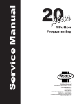
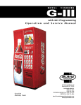
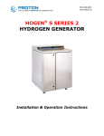
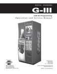
V21 Parts & Service Manual
Trade Equipment
REV A – 10/2012
P/N: 1124016
12.1 PROGRAMMING
SECTION
V21 Trade 12.1 Programming Section | P-1
V21 Parts & Service Manual
Trade Equipment
REV A – 10/2012
P/N: 1124016
All programming of the V21 is done in the service mode as indicated in the following steps
below. The main service modes are indicated in white text and the sub-modes are indicated in
black text.
V21 Trade 12.1 Programming Section | P-2
V21 Parts & Service Manual
Trade Equipment
REV A – 10/2012
P/N: 1124016
THREE-BUTTON PROGRAMMING
All programming of the V21 control board is done in the service mode. To enter the service
mode open the vendor door, find the service mode button located on the control board, then
press and release the service mode button. To scroll though all the service modes, use selection
button one.
The first three selection buttons are used to navigate through the programming as follows:
Button
Description
Usage
Selection Button 1
Up/Down
Increase/Decrease, Next/Previous
Selection Button 2
Enter
Go to sub-level, activate function
Selection Button 3
Exit
Return to previous level, exit, save
FIGURE 1
The controller will automatically return to the Open-Door Sales Mode if:
1. No information from the selection switches is received within approximately 30 seconds.
2. The service mode button is pressed a second time.
3. The (Exit) button is pressed.
When the programming is entered, any established credit is returned. When and if the door is
closed, the controller will exit the service mode and return to the sales mode.
MIS Data
As soon as the outer door is opened, the non-resettable MIS data will be displayed if no errors
exist. “CAns XXX” will flash for approximately 30 seconds, indicating the total number of units
the machine has sold. After 30 seconds, “CASh XX.XX” will begin to scroll, indicating the total
dollar amount the machine has accumulated. NOTE: Pressing selection button one will eliminate
the 30-second wait time and advance you immediately to the “CASh XX.XX” scroll.
To access MIS data by individual selection, press selection button two during the “CAnS XXXX”
or “CASh XX.XX” scroll. Use selection button one to advance forward or backward through the
selections. Please see page PG-7 to choose between count by selection or count by price.
NOTE: The MIS data that is displayed when the outer door is opened (“CAnS XXXX” and CASh
XX.XX”) is non-resettable. This data is accumulated over the life of the control board and can
only be changed by replacing the control board.
V21 Trade 12.1 Programming Section | P-3
V21 Parts & Service Manual
Trade Equipment
REV A – 10/2012
P/N: 1124016
SET-UP AND CODE DESCRIPTION
Eror
Error Display Mode
If selection button two is pressed at the “Eror” prompt, the controller will enter the Error Display
Mode. If no errors have occurred, the display will show “nonE”. If an error has been detected
since the last error reset, the display will show the first error summary code that has occurred. If
selection button three is pressed while displaying any summary code, the controller will return
to the “Eror” prompt.
Note: See the Trouble Shooting section for errors and how to clear them.
EXAMPLE: “CJO1” would indicate a column jam error in column 1.
COIn
Coin Pay Out/Tube Fill Mode
If selection button two is pressed at the “COIn” prompt, the controller will enter the Coin Pay Out
Mode. Pressing selection one will scroll through the denominations and pressing selection
button two will start the denomination flashing. The display will indicate the denomination
along with the number of that coin stored in the coin mechanism. If selection button two is
pressed, a pay out of the displayed value will be made. Coins will continue to pay out as long as
that selection button is held down.
EXAMPLE: If selection button two is pressed while 5 cents is displayed it will pay out a nickel.
When the controller enters the “COIn” mode, the operator is allowed to deposit any coin into the
coin changer’s acceptor when that coin’s tube is not full. The tube inventory level will be displayed
after each coin is accepted.
tESt
Test Mode
If selection button two is pressed at the “tESt” prompt, the controller will enter the Test Mode
where you are able to test the motors, the display, the compressor, the lights, the evaporator
fans and the heater.
UEnd
Vend Testing
Pressing selection button two at the test mode will enter the controller into the vend test mode.
Upon entry into the vend test mode the display will show the first summary test, “COL1” (column
1). Pressing selection button one will scroll through the column selections. Pressing selection
button two will test vend the displayed column. In order to exit the setting, press selection
button three.
V21 Trade 12.1 Programming Section | P-4
V21 Parts & Service Manual
Trade Equipment
REV A – 10/2012
P/N: 1124016
SET-UP AND CODE DESCRIPTION (CONTINUED)
JoG
Jogging the Column
Pressing selection button two at the “JoG” mode, will enter into the Jog test mode. Upon entry
into the Jog test mode the display will show the first summary test, “COL1” (column 1). Pressing
selection button one will scroll through the column selections. Pressing selection button two will
access for (forward) or rEU (reverse). Pressing selection button two again will move the motor
in the desired direction. To exit the setting, press selection button three.
diSP
Display Testing
Pressing selection button one at the Jog test mode will advance the controller to the Display test
mode. Upon entry into the Display test mode the display will flash a series of lines and dashes if
all characters in the display are operational. To exit the setting, press selection button three.
rELY
Relay Testing
Pressing selection button one at the display test mode will advance the controller into the Relay
test mode which allows the user to test the lights, compressor, evaporator fans or the heater.
Upon entry into the relay test mode the display will read “cnPO” for the compressor test. To
scroll through the components for testing, press selection button one. To activate the
component, press selection button two and the “0” will begin to flash. Use selection button one
to toggle between “0” (deactivate) and “1” (activate). Pressing selection button two will activate
the component if the display reads “XXX1”. To exit the setting, press selection button three.
CnPO/1 – Compressor test
Lit0/1 – Light test
FAn0/1 – Evaporator fan test
Htr0/1 – Heater testing
cASh
MIS Data – Cash Mode
If selection button two is pressed at the “CASh” prompt, the display will show the non-resettable
historical amount of money accepted by the machine. If selection button one is pressed, the
display will show “SL 1”(selection one) and the amount received for selection button one.
Continue pressing selection button one to scroll through all of the selections. To exit the setting,
press selection button three.
V21 Trade 12.1 Programming Section | P-5
V21 Parts & Service Manual
Trade Equipment
REV A – 10/2012
P/N: 1124016
SET-UP AND CODE DESCRIPTION (CONTINUED)
SALE
MIS Data – Sales Mode
If selection button two is pressed at the “SALE” prompt, the display will show the non-resettable
historical amount of units sold by the machine. If selection button one is pressed, the display will
show “SL 1” (selection one) and the units sold for selection button one. Continue pressing
selection button one to scroll through all of the selections. To exit the setting, press selection
button three.
COSt
Cost Setting Mode
The purpose of this mode is to enable the controller to set the vend price for each of the
selections. If selection button two is pressed at the “COSt” prompt, the display will indicate “SL 1”.
Pressing selection button one will scroll through all of the selections or “ALL” to have all the
vend prices set at the same price. Pressing selection button two will enter into the displayed
selection button. Pressing selection button one will change the displayed vend price. Pressing
selection button two again will save the price and selection button three will exit the mode.
dCtr
Discount Counter (Only shows when discounts are used)
The discount counter allows you to access the sales and cash data for vends that have been
discounted. Press selection button #2 when the display reads dCtr. The display will change to
read CASh. Press selection button #2 when the display reads CASh. The display will change to
read CASh and XXXX.XX, where XXXX.XX is the value of all discounts towards paid sales. This
total is non-resettable and begins when the discount feature is enabled. Pressing selection
button #1 will scroll through all of the selection buttons and display the value of the discounts
toward product sales. The amounts for the individual selections can be reset using the rules in
the oPts mode. To exit this mode, press selection button #3. The display will return to CASh. To
advance to the sales information, press selection button #1. The display CASh will change to
SALE. Press selection button #2 to access this information. The total number of discounted sales
will be displayed. This total is non-resettable and begins when the discount feature is enabled.
Pressing selection button #1 will scroll through all of the selection buttons and display each
selection’s number of discounted sales. The amounts for the individual selections can be reset
using the rules in the oPts mode.
FCtr
Free Counter (Only show if free vends during closed-door sales mode have been made)
The free counter allows you to access the sales and cash data (loss) for vends that have been
free. Press selection button #2 when the display reads FCtr. The display will change to read
XXXX.XX, where XXXX.XX is the value of all lost money based on the price value setting. This
total is non-resettable and begins when the free vend override feature is enabled. Pressing
selection button #1 will change to the second screen. The display will change to read SALE
XXX.XX. It will display the total number of free vends that have occurred. This total is nonresettable and begins when the free vend override feature is enabled. Press selection button #3
to exit the mode.
V21 Trade 12.1 Programming Section | P-6
V21 Parts & Service Manual
Trade Equipment
REV A – 10/2012
P/N: 1124016
SET-UP AND CODE DESCRIPTION (CONTINUED)
dSEt
Depth Setting Mode
The purpose of this mode is to enable the controller to set the vending depth for each column.
If selection button two is pressed at the “dSEt” prompt, the display will indicate “0X”. Pressing
selection button one will scroll through all of the columns. Pressing selection button two will
enter into the displayed column. Pressing selection button one again will change the displayed
depth settings from 1-4. Pressing selection button two will save the depth setting and selection
button three will exit the mode.
OPtS
Option Mode
If selection button two is pressed at the “OPtS” prompt, the controller will enter the Option
mode. The purpose of this mode is to allow the controller to select the configuration options
desired.
Display
Description
Meaning
Force Select
Force select enabled (y) or disabled (n)
Bill Escrow
Bill Escrow enabled (y) or disabled (n)
Error/Sold Out Indicator
Error/Sold Out indicator “o” enabled (y) or disabled (n)
Single Price
Single Price enabled (y)/Multi-Price enabled (n)
Count by Price/Count
y = count by price
by Selection
n = count by selection
CC
Correct Change Light
Correct Change Light enabled (y)/Correct Change Light
disabled (n)
OP
Allow Overpay
Allow overpay enabled (y)/Allow overpay disabled (n)
SC
Save Credit
Credit will remain for 5 minutes (y)/Credit will remain
indefinitely (n)
NU
Multi Vend
Multi vend enabled, single vend disabled (y)/ Single
vend enabled, multi vend disabled (n)
dL
Learning Mode*
Learning mode enabled (y)/Learning mode disabled (n)*
AR
Auto MIS reset
MIS data will reset with DEX read (y)/MIS data will not
reset with DEX read (n)
FS
bE
SE
SP
ct
FIGURE 2
* The learning mode uses self adaptive logic to “learn” what the depth setting of the column is,
in the event that the control board depth setting isn’t programmed properly.
V21 Trade 12.1 Programming Section | P-7
V21 Parts & Service Manual
Trade Equipment
REV A – 10/2012
P/N: 1124016
SET-UP AND CODE DESCRIPTION (CONTINUED)
StS
Space-to-Sales Setting Mode
If selection button two is pressed at the “StS” prompt, the controller will enter the Space-toSales option. Upon entry into this setting the display will show the current option setting.
Pressing selection button one will scroll through the various space to sales options as listed
below. Pressing selection button two will change the current option and selection button three
will save the desired option. For proper configuration settings refer to the label located on
the inner door shear panel (See figure 3.)
SPACE-TO-SALES CONFIGURATIONS
SEL#
1
2
3
4
5
6
7
8
9
10
11*
12*
STS10
COL
1
2
3
4
5
6
7
8
9
10
~
~
STS9
COL
1,2
1,2
3
4
5
6
7
8
9
10
~
~
STS8
COL
1
2
3
4
5
6
7
8
~
~
~
~
STS7
COL
1
2
3
4
5
6
7
~
~
~
~
~
STS6
COL
1,2,3
1,2,3
1,2,3
4
5
6
7
8
9
10
~
~
STS5
COL
1,2
1,2
3
4
5
6
7
8
~
~
~
~
STS4
COL
1
1
2
2
3
4
5
6
7
8
9
10
STS3
COL 1,2
1,2
3
4
5
6
7
8
9
9
10
10
STS2
COL ALL
ALL ALL ALL ALL ALL ALL ALL ALL ALL ALL ALL STS1
COL
NONE
NONE
NONE
NONE
NONE
NONE
NONE
NONE
NONE
NONE
NONE
NONE
FIGURE 3
*Where available
Note: If none of the space-to-sales configurations are suitable, the operator can use the Custom
Space-to-Sales Setting Mode.
CStS
Custom Space-to-Sales Setting Mode
If selection button two is pressed at the “CStS” prompt, the controller will enter the Custom
Space-to-Sales option. Upon entry into this setting the display will show the current selection
setting followed by the columns connected to that selection button.
Programming Connection Option
If selection button two is pressed while “SL X” is displayed, the display will change to “C0 1”.
Pressing selection button one will increase or decrease the column number displayed. Pressing
selection button two will actuate the changed connection status of the column number
displayed. If the column number is flashing it is assigned to the selection that was entered. If the
column number is steady, it is not assigned to the selection button. To exit this mode, press
selection button three to display “SAVE”, then press selection 2 to confirm save.
V21 Trade 12.1 Programming Section | P-8
V21 Parts & Service Manual
Trade Equipment
REV A – 10/2012
P/N: 1124016
SET-UP AND CODE DESCRIPTION (CONTINUED)
Cddr
Closed Door Data Retrieval Mode
If selection button two is pressed at the “Cddr” prompt, the controller will enter the Closed Door
Data Retrieval Mode by displaying “XXXX” where “XXXX” is the password. Pressing selection
button number one while the digits are flashing will change the current password. The available
digits are 0-6. (See note below.) Pressing selection button two will save the change and
advance to the next digit. In order to save the password and exit the mode, press selection
button two while the last/fourth digit is flashing.
Note: If one of the digits in the password is “0” this feature will be disabled since selection button
“0” does not exist.
Note: This feature is not available when the vend price is set to “0.00”.
LAnG
Language Mode
If selection button two is pressed at the “LAnG” prompt, the controller will enter the Language
Mode by displaying the currently assigned language. The available languages are EnG – English,
Frn – French, GEr – German, ItA – Italian, Port – Portuguese, and ESP – Spanish. Pressing
selection button one will toggle though the language options. If selection button two is pressed,
the display will save the language change and return the display to LAnG.
CLOC
Clock Setting Mode
If selection button two is pressed at the “CLOC” prompt, the controller will enter the Clock Mode
which allows you to set the clock on the control board. This field must be set in order to operate
any modes associated with the time. Pressing selection button two while any of the options are
displayed will enter you in to the clock setting options. Pressing selection button one will toggle
you through the options. Pressing selection button three will exit this mode.
CLOCK SETTING OPTIONS
YEAr
dAtE
Hour
dSt
CtLC
Current Year (Example: 2002)
Current Date (month, day)
Current Time (hours, minutes)
Daylight Savings Time
Clock Control
V21 Trade 12.1 Programming Section | P-9
V21 Parts & Service Manual
Trade Equipment
REV A – 10/2012
P/N: 1124016
SET-UP AND CODE DESCRIPTION (CONTINUED)
LitE
Lighting Control Mode
If selection button two is pressed at the “LitE” prompt, the controller will enter the Lighting
Control Mode which allows you to have the lights turned off and on during specific time periods
to conserve energy. Pressing selection button two while any of the settings are displayed will
enter you in to the light control settings. Pressing selection button one will toggle you through
the options. Pressing selection button three will exit this mode.
LIGHTING CONTROL SETTINGS
Enb
StrI
dAY
Hour
End1
dAY
Hour
Str2
dAY
Hour
End2
dAY
Hour
rFrG
Lighting control enabled (1)/disabled (0)
Start Time – Time lights shut off
Days associated with start time
Hour associated with start time
End Time – Time lights turn back on
Days associated with end time
Hour associated with end time
2nd Start time – time lights shut off
Days associated with 2nd start time
Hour associated with 2nd start time
2nd End Time – Time lights turn back on
Days associated with 2nd end time
Hour associated with 2nd end time
Refrigeration Mode
If selection button two is pressed at the “rFrG” prompt, the controller will enter the Refrigeration
Control Mode by displaying “SEtP” for set point temperature. Pressing selection button two
again enters the temperature settings from “hhhh”(warmest) to “cccc”(coldest). Pressing
selection button one will toggle through the settings. If selection button two is pressed, the
display will return to “SEtP”. Pressing selection button one will change the display to “tNP” for
temperature. To view the temperature, press selection button two. To change the degree scale,
press selection button two when the display reads “ForC” for Fahrenheit or Celsius. To change
the current degree scale, press selection button one to scroll between F and C. Pressing
selection button two will return the display to “ForC”.
Note: The displayed thermostat setting and the actual temperature sensor reading for
refrigeration control are listed below in Figure 4:
V21 Trade 12.1 Programming Section | P-10
V21 Parts & Service Manual
Trade Equipment
REV A – 10/2012
P/N: 1124016
SET-UP AND CODE DESCRIPTION (CONTINUED)
Thermostat Setting Displayed
cccc
ccc
cc
c
norn
h
hh
hhh
hhhh
Cut-in Temperature (F)
34°
35°
36°
37°
38°
39°
40°
41°
42°
Cut-out Temperature (F)
30°
31°
32°
33°
34°
35°
36°
37°
38°
Nominal Temperature (F)
32°
33°
34°
35°
36°
37°
38°
39°
40°
Nominal Temperature (C)
0
0.6
1.1
1.7
2.2
2.8
3.3
3.9
4.4
FIGURE 4
There are two sub-modes within the refrigeration mode that can be activated to achieve energy
conservation
The first sub-mode, FAnX, refers to an optional evaporator fan relay. When X =
0 - the fan mode is disabled and the evaporator will turn on/off with the activation of the
compressor
1 - (Fan Mode 1) the evaporator fan will turn off 5 minutes after the compressor fan is turned
off
The second sub-mode, dEFX, refers to the Periodic Defrost mode. If X =
0 - the periodic defrost mode is disabled
1 - the machine will defrost every 6 hours for 30 minutes - used in high humidity
environments .
Within the refrigeration mode, there is also a refrigeration conservation mode which raises the
cabinet temperature 18º F or 10º C during specified periods of time. Pressing selection button
two while any of the settings are displayed will enter you in to the refrigeration control settings.
Pressing selection button one will toggle you through the options. Pressing selection button
three will exit this mode.
V21 Trade 12.1 Programming Section | P-11
V21 Parts & Service Manual
Trade Equipment
REV A – 10/2012
P/N: 1124016
SET-UP AND CODE DESCRIPTION (CONTINUED)
REFRIGERATION CONTROL SETTINGS
Enb
Refrigeration control enabled (1)/disabled (0)
Str1
Start Time – Time temperature rises 18°F/10°C
dAY Days associated with start time
Hour Hour associated with start time
End1
End Time – Time temperature returns
dAY Days associated with end time
Hour Hour associated with end time
Str2
2nd Start time – Time temperature rises 18°F/10°C
dAY Days associated with 2nd start time
Hour Hour associated with 2nd start time
End2
2nd End Time – Time temperature returns
dAY Days associated with 2nd end time
Hour Hour associated with 2nd end time “nno” – Monday
“tUE” – Tuesday
“UUE” – Wednesday
“Thu” – Thursday
“Fri” – Friday
“SAt” – Saturday
“Sun” – Sunday
“ALL” – All Days
bLC1
Block Selection Setting
This feature is used to choose a group of selections and the time when those selections will be
blocked from vending product. If selection button two is pressed at the “bLC1” or “bLC2” prompt,
the controller will enter the Selection Blocking Control Mode. Upon entry into this program, the
display will show the first sub-mode “CtL1” or “CtL2” depending on which blocking mode you are
using. Using selection button one will let the operator toggle between the following modes:
V21 Trade 12.1 Programming Section | P-12
V21 Parts & Service Manual
Trade Equipment
REV A – 10/2012
P/N: 1124016
SET-UP AND CODE DESCRIPTION (CONTINUED)
BLOCK SELECTION OPTIONS
diSC
CtL1
SbL1
Str1
dAY
hour
Controls blocking option
StP1
dAY
hour
Set time for machine to turn back on
Set selection buttons – (y) assigned/(n) not assigned
Set time for machine to turn off
Set days for blocking to start
Set hours for blocking to start
Set days for blocking to stop
Set hours for blocking to stop
Discount Setting Mode
This feature is used to choose a group of selections that will be discounted, the amount of
discount, and the time when the discount will occur. If selection button two is pressed at the
“diSC” prompt, the controller will enter the Discount Setting Mode. Upon entry into this program
the display will show “CtL1”. If selection button one is pressed it will toggle through the discount
setting mode as listed below. Pressing selection button three will save the settings and return to
the “diSC” mode.
DISCOUNT SETTING OPTIONS
CtL1
SdSC
Strt
dAY
Hour
Turns the discount setting On/Off
StoP
dAY
Hour
LESS
Set time for discounting to stop
Set selection buttons – (y) assigned/(n) not assigned
Set time for discounting to begin
Set days to discount
Set time for discounting to begin
Set days for discounting to stop
Set time to start (24 hours)
Set discount amount
V21 Trade 12.1 Programming Section | P-13
V21 Parts & Service Manual
Trade Equipment
REV A – 10/2012
P/N: 1124016
SET-UP AND CODE DESCRIPTION (CONTINUED)
OUEr
Over-Ride Mode (Units equipped with optional key switch)
This feature is used to allow you to manually over-ride (via a key switch) pricing, blocking, low
energy operation and discounting. If selection button two is pressed at the “OUEr” prompt, the
controller will enter the Over-Ride Mode. Upon entry into this program the display will show
“FrEn”. If selection button one is pressed it will cycle through the override setting options as
listed below. Pressing selection button three will save the currently displayed setting and return
the operator to the “OUEr” prompt.
OVER-RIDE SETTING OPTIONS
FrEn
FrEn
Enable/Disable free vend (Edit mode Y/N)
bLCn
Selection blocking over-ride
Litn
Lighting over-ride
rFGn
Refrigeration over-ride
dScn
Discounting over-ride
Over-Ride Free Vend
If selection button two is pressed at the “FrEn” prompt, the controller will enter the Free Vend
Enable Option. Upon entry into this program the display will show the current setting “FrEn”.
Press selection button two. Pressing selection button one will toggle between “y” for enabled
and “n” for disable. Pressing selection button two will save the currently displayed setting.
Pressing selection button three will return the operator to the “FrEn” prompt.
“Y” = Enable free vend.
“N” = Disable free vend.
bLCn
Over-Ride Selection Blocking
If selection button two is pressed at the “bLCn” prompt, the controller will enter the Selection
Blocking Over-Ride Enable Option. Upon entry into this program the display will show the
current setting “bLCn”. Press selection button two. Pressing selection button one will toggle
between “Y” for enable and “N” for disable. Pressing selection button two will save the currently
displayed setting. Pressing selection button three will return the operator to the “bLCn” prompt.
“Y” = Enable selection blocking.
“N” = Disable selection blocking
V21 Trade 12.1 Programming Section | P-14
V21 Parts & Service Manual
Trade Equipment
REV A – 10/2012
P/N: 1124016
SET-UP AND CODE DESCRIPTION (CONTINUED)
Litn
Over-Ride Lighting
If selection button two is pressed at the “Litn” prompt, the controller will enter the Lighting
Over-Ride Option. Upon entry into this program the display will show the current setting “Lit4”
for enable and “Litn” for disable. Pressing selection button one will toggle between “y” for
enabled and “n” for disable. Pressing selection button two will save the currently displayed
setting. Pressing selection button three will return the operator to the “Litn” prompt.
“Y” = Enable Over-Ride Lighting blocking.
“N” = Disable Over-Ride Lighting blocking
rFGn
Over-Ride Refrigeration
If selection button two is pressed at the “rFGn” prompt, the controller will enter the
Refrigeration Over-Ride Option. Upon entry into this program the display will show the current
setting “rFG4” for enable and “rFGn” for disable. Pressing selection button one will toggle
between “y” for enabled and “n” for disable. Pressing selection button two will save the currently
displayed setting. Pressing selection button three will return the operator to the “rFGn” prompt.
“Y” = Enable refrigeration over-ride.
“N” = Disable refrigeration over-ride.
dSCn
Over-Ride Discount
If selection button two is pressed at the “dSCn” prompt, the controller will enter the Discounting
Over-Ride Enable Option. Upon entry into this program the display will show the current setting
“dSC4” for enable and “dSCn” for disable. Pressing selection button one will toggle between “y”
for enabled and “n” for disable. Pressing selection button three will save the currently displayed
setting and return the operator to the “dSCn” prompt.
“Y” = Enable discount over-ride.
“N” = Disable discount over-ride.
V21 Trade 12.1 Programming Section | P-15
V21 Parts & Service Manual
Trade Equipment
REV A – 10/2012
P/N: 1124016
V21 Trade 12.1 Programming Section | P-16
V21 Parts & Service Manual
Trade Equipment
REV A – 10/2012
P/N: 1124016
V21 Trade 12.1 Programming Section | P-17
V21 Parts & Service Manual
Trade Equipment
REV A – 10/2012
P/N: 1124016
NOTE: If the outer door is left open for over an hour, the lights, and compressor will
become active. In order to over-ride this option, press the door switch one time.
V21 Trade 12.1 Programming Section | P-18