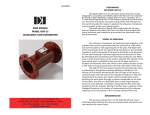
1
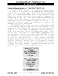
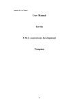
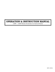
OPERATORS
INSTRUCTION MANUAL
For
CIRCUIT BREAKER TEST SET
MODEL DDA-1600
It is essential that this instruction book be read thoroughly by the operator of the test equipment before
putting the equipment in service.
Part No._ 50551
Rev. 1, 03/12/1998
Revision History
Revision
0
1
ECN #
Date
03/11/97
27999
03/12/98
IMPORTANT
The information and data contained within this instruction manual are proprietary property of
AVO International. The equipment described herein may be protected by one or more U.S.
patents. AVO International specifically reserves to itself all rights to such proprietary information
as well as all rights under any such patent, none of which is waived by the submission of this
instruction manual.
The recipient, if a Government agency, acknowledges that this instruction book and the
equipment described were procured with "Limited Rights" to technical data as described in
ASPR 9-203 (b).
Copyright AVO International Inc. 1997
TABLE OF CONTENTS
SECTION I .................................................................................................................................... 1
1.
INTRODUCTION ................................................................................................... 1
A.
GENERAL DESCRIPTION ........................................................................ 1
B.
SPECIFICATIONS ..................................................................................... 2
SECTION II ................................................................................................................................... 4
1.
DESCRIPTION of CONTROLS and INSTRUMENTATION................................... 4
A.
GENERAL DESCRIPTION ........................................................................ 4
B.
CONTROLS AND INSTRUMENTATION ................................................... 4
SECTION III .................................................................................................................................. 9
1.
FRONT PANEL DISPLAY AND PROGRAMMING MENUS .................................. 9
2.
Flow Diagram of Display Menus .......................................................................... 10
A.
METERING DISPLAY.............................................................................. 10
B.
MAIN MENU ............................................................................................ 10
C.
LCD CONTRAST MENU ......................................................................... 11
D.
SCR CONTROL MENU ........................................................................... 11
E.
PULSE DURATION AND FIRING ANGLE MENUS ................................ 12
F.
ACQUISITION CONTROL MENU ........................................................... 13
SECTION IV INPUT AND OUTPUT CIRCUITS .......................................................................... 14
1.
INPUT: ................................................................................................................. 14
A.
INPUT VOLTAGE .................................................................................... 14
B.
INPUT LEADS ......................................................................................... 14
C.
GROUNDING .......................................................................................... 14
D.
SAFETY PRECAUTIONS ........................................................................ 14
SELECTION OF INPUT LEADS .............................................................. 14
A.
SELECTION OF OUTPUT CONNECTIONS ........................................... 16
SERIES OR PARALLEL OUTPUT .......................................................... 16
SERIES CONNECTION .......................................................................... 17
PARALLEL CONNECTION ..................................................................... 18
C.
DUTY RATINGS AND OVERLOAD CAPACITIES .................................. 19
DUTY CYCLES ON ............................................................................................ 19
TEST PROCEDURES AND TEST SET OPERATION ................................................................ 20
UNIT INTERCONNECTION ............................................................................................ 20
SECTION V ................................................................................................................................. 20
1.
TEST PROCEDURES FOR TESTING OF MOTOR OVERLOAD RELAYS ....... 20
2.
TEST PROCEDURE FOR TESTING OF MOLDED CASE AND LOW VOLTAGE
POWER CIRCUIT BREAKERS ........................................................................... 24
3.
MAINTENANCE OF PROTECTIVE APPARATUS MAINTENANCE OF MOTOR
OVERLOAD RELAYS ......................................................................................... 28
4.
MAINTENANCE OF MOLDED CASE CIRCUIT BREAKERS ............................. 31
5.
MAINTENANCE OF LOW VOLTAGE POWER CIRCUIT BREAKERS ............... 33
6.
SUGGESTED RECORD FORMS - INSPECTION AND TEST RESULTS ......... 35
SECTION VI ................................................................................................................................ 36
2.
SERVICE DATA .................................................................................................. 37
SECTION VII. .............................................................................................................................. 39
1.
SCHEMATIC DRAWING ..................................................................................... 39
i
BULLETIN
SECTION ISECTION I
1. INTRODUCTION.
INTRODUCTION
A.
GENERAL DESCRIPTIONA. GENERAL DESCRIPTION
2
B.
SPECIFICATIONSB. SPECIFICATIONS
DDA-1600 Specifications
Input
DDA-1600
460 V
5%, 60 Hz, 150 A
A variety of input power options, including 415 V/50 Hz, 380 V/50 Hz, are available.
Output
Output Current
Model Number
DDA-1600
Maximum
Continuous
Current
Max. Amps Through an Air
Frame Circuit Breaker
Max. Amps Through
a Molded Case
Circuit Breaker
1,600 A
19,200 A
14,400 A
Instrumentation
Digital Ammeter
Operating Mode
Memory
Continuous
Digital Display
5 - digit display with 0.281 in (7 mm) numerals
Ranges
200 / 2,000 / 20,000 / 200,000 A
Accuracy
Continuous - 1% of Reading
Pulse (Peak) - 2% of Reading
Pulse (RMS) - 1.5% of Reading
Digital Timer
Digital Display
5 - digit display with 0.281 in (7 mm) numerals
Ranges
0.0001 to 99999 s
0.0001 to 99999 cycles
Accuracy
1% of Reading for times that are 2 cycles and longer
Digital Voltmeter
Operating Mode
Input Voltage
Output Voltage
External Voltage
Digital Display
5 - digit display with 0.281 in (7 mm) numerals
Ranges
600 V
Accuracy
1% of Reading
Dimensions and Weight
3
ModelNo.
DDA-1600
Module
Weight
Dimensions
lb
kg
H x W x D (in.)
H x W x D (cm.)
Control and
Instrumentation
19
8.6
9.9 x 14.1 x 11.3
27 x 54 x 24.8
Power
100
45.4
14 x29 x 12.5
35.6 x 73.6 x 31.8
Output
210
95.4
7.5 x 33 x 45.7
19 x 83.8 x 45.7
4
SECTION IISECTION II
1. DESCRIPTION of CONTROLS and INSTRUMENTATION. DESCRIPTION of CONTROLS
and INSTRUMENTATION
A. GENERAL DESCRIPTIONA. GENERAL DESCRIPTION
AVO International Circuit Breaker Test Sets are portable high current units designed for
testing and adjusting low voltage circuit breakers and other current actuated devices. The
units incorporate a variable high current ac output, and uses the latest in Digital Signal
Processing (DSP) technology to control the circuit breaker test sets as well as measure the
reactions of the breaker under test. The units are self protected against overloads and short
circuits.
B. CONTROLS AND INSTRUMENTATIONB. CONTROLS AND INSTRUMENTATION
1) OUTPUT CONTROLS:
Adjustment of the output is accomplished by the combination
of the OUTPUT SELECTOR Switch and VERNIER
CONTROL.
a)
OUTPUT SELECTOR
Switch:
This is a multi-position switch which provides coarse
adjustment of the output. Position 1 provides minimum output.
The last position provides maximum output. The OUTPUT
SELECTOR Switch is interlocked with the output initiating
circuit. Depressing the switch to change positions operates
the interlock and de-energizes the output and will not reenergize without pressing the START Button.
b)
VERNIER CONTROL
(Power Stat):
Provides fine adjustment of the output between steps of the
OUTPUT SELECTOR Switch.
2. Circuit Breaker:
Functions as the input POWER ON/OFF Switch and also
provides short-circuit and overload protection.
3. FUSE:
Protects control and isolation transformers
4. AUX. OUTLET
A ground fault protected 120-volt outlet is provided for
convenient connection of accessory equipment.
5. Input Receptacles
Receptacles for input power connection.
6. Equipment Ground
Test set chassis ground. For safety purposes, this
should be connected to a power system ground .
5
Front View
Reverse View
6
4.
DDA CONTROL PANEL
TEST
1. START Button - Energizes the output
2. STOP Button - De-energizes the output.
3. EXT. START Terminals - An external switch can be plugged into these terminals (blue) to
provide remote initiation of the test set.
TEST FUNCTION
4. TIMER STOP MODE - Three modes of operation are available to control the output and
timer operation.
C.A. (Current Actuate) - When the device to be tested has no contacts other than those
involved in the passing of test current, this type of operation is used. In this position, the
timer will run from the initiation of the test until the test circuit is interrupted. This position is
the position most commonly used for controlling timer operations (Default setting). The
output will de-energize when the current level drops below 8% of range.
N.O. (Normally Open) - When it is desired to control the timer from a set of normally open
contacts (such as an auxiliary contact) this type of operation may be used. In this position,
the timer will run from the initiation of the test until the opening of the contacts connected to
the TIMER STOP (Yellow) terminals.
N.C. (Normally Closed) - When it is desired to control the timer from a set of normally closed
contacts (such as a multi-pole circuit breaker), this type of operation may be used. In this
position, the timer will run from the initiation of the test until the opening of the contact
connected to the TIMER STOP (Yellow) terminals.
7
5. TIMER STOP Terminals - These terminals (yellow) facilitate connection to a set of contacts
on the device under test to monitor contact opening and closure. The timer stops and
output is de-energized when the device operates (used in conjunction with the TIMER
STOP MODES of N.O. and N.C).
6. TIME UNITS Selection- Selects the mode of count; either cycles or seconds.
7. OUTPUT Mode - The following two selections are available
PULSE - When selected, the output of the test set is on for a short, specified time period
(default is 5 cycles) and then is turned off. (Should the device under test operate after
pushing the START Button, the output will be de-energized). This position is normally used
when setting the test current prior to the timing test and providing short high current pulses
for instantaneous tests. However, the duration of this output pulse can be programmed via
the Display Menu. (See the Section III, E. Front Panel Display and Programming Menus.)
(Default Setting).
MAINT. - When selected, and the START Button is pressed, the control circuit maintains the
output of the test set until the device under test operates or the STOP Button is pressed.
This is the normal position for Time Delay tests.
VOLTS (voltmeter selection) Switches
8. VOLTS - three different selections are available for display
IN - When this voltage display selection is made, the voltage at the input plugs of the test set
will be displayed (Default Setting).
OUT - When this voltage display selection is made, the voltage at the output terminals of the
test set will be displayed.
EXT. - When this voltage display selection is made, the voltage applied to the EXT. VOLTS
terminals will be displayed.
9. EXT. VOLTS terminals - These two terminals enable the digital voltmeter to
measure external a.c. voltages up to 600 Volts.
AMMETER
10.AMMETER RANGE Switches - Selects the desired full scale range of the meter.
NOTE: The output current level from the test set must be at least 8 percent
of any full
scale value before the ammeter will indicate an output reading.
Please be aware that
changing ammeter ranges while the output is energized may result in erroneous
ammeter readings. The 4 range
selections are 0.2kA/ 2kA/ 20kA / and 200 kA range.
Default Setting is the 200 kA range.
11. AMMETER MODE
MEM/CONT - Selects the mode of the ammeter circuit. In the MEM position,
the highest
measured current is indicated on the ammeter. The CONT mode permits the ammeter to
continually indicate the value of output current.
When in the CONT. and MAINT. Modes
of operation, it will require 30 cycles of output current before a current value will be
displayed. Default Setting is MeM.
8
SER/PAR - When operating the unit with the output in a series configuration,
this switch
must be in the SERIES position in order for the ammeter to read the correct amount of
output current. (See Section IV, 2, A for more details.)
The default setting is
PARALLEL.
FRONT PANEL DISPLAY AND INDICATORS
12. LCD Display Panel - This panel displays Output Amperage, Vac, and Time.
It is also
used to program many other features of the DDA control panel (See Section III, Front
Panel Display and Programming Menus for more details).
13. Front Panel Indicators
Over Range - Illuminates to indicate that output current has exceeded the
RANGE selected.
AMMETER
Output Energized - Illuminates to indicate that the SCR has gated and the
energized.
output is
Thermal Warning - Indicates that the thermal status of the test set is approaching an over
temperature condition.
Thermal Shutdown - Indicates that the thermal status of the test set has reached an over
temperature condition. The test set will not operate as long as there is an over temperature
condition.
14. Softkeys - Used to set programmable functions indicated on the LCD display panel.
9
SECTION IIISECTION III
1. FRONT PANEL DISPLAY AND PROGRAMMING MENUS.
DISPLAY AND PROGRAMMING MENUS
2. Flow Diagram of Display
Menus. Flow Diagram
of Display Menus
A. METERING DISPLAYA.
METERING DISPLAY
10
FRONT PANEL
All of the programmable menu options may be accessed by pressing the soft key
underneath the word MENU in the metering display screen. When pressed, the following
display will appear.
B. MAIN MENUB.
MAIN MENU
From the MAIN MENU the user may select programming menus to make adjustments to the LCD display
contrast, SCR controls, or Acquisition control (current calculation method). The user may also select to EXIT
back out to the metering display screen. The desired option would be selected by pressing the soft key directly
beneath that option.
11
C. LCD CONTRAST MENUC.
LCD CONTRAST MENU
The LCD CONTRAST MENU provides two options for optimizing a user s ability to view the
display. Pressing the soft key directly beneath UP will cause the intensity of the display to
be increased. Pressing the soft key directly beneath DOWN will cause the intensity of the
display to be decreased. This menu also provides the option to return to the previous menu
by pressing the soft key directly beneath EXIT.
D. SCR CONTROL MENUD.
SCR CONTROL MENU
The SCR CONTROL MENU provides the ability to enter into two different areas of SCR
adjustment. Pressing the soft key directly beneath PULSE DURATION will display a menu
that will allow the user to program the number of cycles that the output of the test set will be
energized during a momentary pulse. Pressing the soft key beneath FIRING ANGLE will
display a menu that will allow the user to program the angle at which the output signal of the
test set is initially energized.
12
E. PULSE DURATION AND FIRING ANGLE MENUS
The PULSE DURATION MENU allows the user to program the number of cycles that the output
of the test set will energized during a momentary pulse. The number of cycles can be
increased or decreased by pressing the soft keys directly beneath UP or DOWN. Pressing the
soft key beneath EXIT will return the user to the previous menu. The default pulse duration
setting is 5 cycles.
The FIRING ANGLE MENU allows the user to program the initial firing angle at which the output
signal of the test set is energized. This is important when dealing with asymmetrical waveforms.
The more inductive the test specimen, the more asymmetrical the output of the test set will be
due to DC offset. Asymmetry in the output of the test set has become of increased importance
when performing instantaneous trip tests on circuit breakers. By providing the ability to adjust
the firing angle of the test set, the user can minimize the effect of DC offset and therefore collect
more accurate information with regard to the instantaneous characteristics of the test specimen.
See ACQUISITION CONTROL MENU for information on how to determine if the output of the
test set is symmetrical and how to adjust the firing angle if it is not. The default firing angle is
70O.
13
F. ACQUISITION CONTROL MENUF. ACQUISITION CONTROL MENU
The Acquisition Control MENU allows the user to select between two different current
measurement methods. By pressing the softkey directly beneath either PEAK or RMS, the
user selects which calculation will be used in displaying measured current on the metering
display. PEAK measures the highest peak and multiplies it by a constant 0.707. This
method of measurement should initially be compared to the RMS measurement method
(with all output setting being the same), which is a true rms measurement. If the output
waveform is symmetrical, the two measurements will be approximately the same current
value. If these two measurements are not approximately the same value, adjust the firing
angle in such a way as to bring the two measurements closer together. Although the
PEAK and RMS measurement will never be the same value, the goal is to find the
firing angle that will bring these two measurements as close together as possible in
order to minimize DC offset. See FIRING ANGLE MENU for adjustment of firing angle.
The method of current measurement is selected by pressing the soft key beneath the
desired method. Pressing the softkey beneath EXIT will return the user to the previous
menu.
NOTE: The DDA controller will default to the PEAK Measurement Method. Most modern
day trip units are RMS sensing devices. Therefore it is highly recommended that the
Measurement Method be changed from PEAK to RMS upon powering up the test
equipment. Because the majority of electronic trip units on circuit breakers manufactured
today are RMS sensing,
it is suggested to
leave the DDA unit in
RMS mode for
most testing
applications.
However, some of the
older styles of
circuit breakers have
peak sensing
instantaneous trip
elements. In
these cases it would be
desirable to select
the PEAK Measurement
Method in order to
more closely model the
current
measurement method of
the circuit breaker
under test.
14
SECTION IV INPUT AND OUTPUT CIRCUITSSECTION IV INPUT AND OUTPUT CIRCUITS
1. INPUT:.
INPUT
A. INPUT VOLTAGEA. INPUT VOLTAGE: The AVO International Circuit Breaker Test Sets
are designed to operate on a single phase voltage source. If the nominal rated voltage
source is not available, or if use at various locations requires the capability to operate
the test set from several different input voltages an optional input autotransformer may
be used (see Sales Bulletin for description).
B. INPUT LEADSB.
INPUT LEADS: The AVO International Circuit Breaker Test Sets are
designed to operate on a single phase voltage source. If the nominal rated voltage
source is not available, or if use at various locations requires the capability to operate
the test set from several different input voltages an optional input autotransformer may
be used (see Sales Bulletin for description).
NOTE: To achieve published output currents, the rated input voltage must be maintained at
the test set terminals during the test.
C. GROUNDINGC.
GROUNDING: The AVO International Circuit Breaker Test Sets are
designed to operate on a single phase voltage source. If the nominal rated voltage
source is not available, or if use at various locations requires the capability to operate
the test set from several different input voltages an optional input autotransformer may
be used (see Sales Bulletin for description).
D. SAFETY PRECAUTIONSD. SAFETY PRECAUTIONS:
CAUTION
For safety of the operator, it is absolutely essential that the test set be properly and
effectively grounded.
SELECTION OF INPUT LEADSSELECTION OF INPUT LEADS:
When utilizing maximum output from the test set, the input line currents may be as high as
400% of nameplate rating. The following table has been prepared to aid in selecting the
proper wire size for the input leads. To use the table, follow these four steps:
1.
2.
3.
4.
Determine the rated input current from the nameplate on the test set. Be sure to
choose the correct current for the input voltage being used.
Multiply this value by four.
Determine the length of input lead required. This is in circuit-feet, therefore it is the
one-way distance from the test set to the power source.
Select the proper wire size from the table using factors 2 and 3 above.
15
NOTE: For input currents exceeding 600 amperes, it is recommended that 2/0 cable
be used and not exceed 50 feet in length.
LENGTH OF INPUT LEADS
DISTANCE FROM TEST SET TO POWER SOURCE
FOUR TIMES (4X)
RATED INPUT POWER 20
50
75
100
125
150
175
200
225
250
275
300
325
350
375
400
425
450
475
500
525
550
575
600
8
8
8
8
8
8
8
8
8
8
8
8
8
8
8
8
8
6
6
6
6
6
6
40
60
80
100
120
MINIMUM WIRE SIZE A.W.G.
8
8
8
8
8
8
8
8
6
6
6
6
4
4
4
4
4
4
4
2
2
2
2
8
8
8
8
8
6
6
6
4
4
4
4
2
2
2
2
2
2
2
1
1
1
1
8
8
8
6
6
4
4
4
4
2
2
2
2
2
1
1
1
1/0
1/0
1/0
1/0
2/0
2/0
16
8
8
6
6
4
4
4
2
2
2
2
1
1
1/0
1/0
1/0
2/0
2/0
2/0
2/0
8
8
6
4
4
2
2
2
2
1
1
1
1/0
2/0
2/0
2/0
140
FEET
8
6
4
4
2
2
2
1
1
1/0
1/0
2/0
2/0
2/0
The wire sizes in this
chart will result in
voltage drops of ten
volts or less
2. OUTPUT:
A. SELECTION OF OUTPUT CONNECTIONSA.
SELECTION OF OUTPUT
CONNECTIONS: Two output connections, parallel and series, provide various voltage
and current ratings to adapt AVO International Circuit Breaker Test Sets to a wide
variety of test circuit impedances.
The test sets can be operated most efficiently by utilizing the parallel connection, which
provides the HIGHEST CURRENT rating consistent with being able to obtain the desired
test current. In this way, finer adjustment can be obtained by making maximum use of the
variable autotransformer range. Even the smallest currents can be obtained from the
parallel connection. The series connection should be used only when testing high
impedance devices where the parallel connection does not have sufficient voltage to "push"
the desired test current through the device. The operator should start with the parallel
connection and move to the series connection only when necessary. To operate the test set
in the parallel connection does not require any changes be made by the operator. However
the test set in series requires that a special series bar be placed on the output bus to
complete the series connection.
SERIES OR PARALLEL OUTPUTSERIES OR PARALLEL OUTPUT:
The test set can be used to provide either a 6 or a 12 volts. This is selected through the
connection of the output bus. Refer to Figure #1 and Figure # 2 for output connections. The
proper test set configuration must be selected to provide correct metering.
1.
SERIES supplies double the voltage and half of the available output current. This is
used to test breakers with high characteristic impedance.
2.
PARALLEL supplies all of the current but half of the available output voltage. This is
used to test breakers with low characteristic impedance.
17
Figure #1
SERIES CONNECTIONSERIES CONNECTION
1.
Connect the S-Bar to output terminals 2 and 3.
2.
Connect test cables to terminals 1 and 4.
1
2
S-Bar
3
4
18
Figure #2
PARALLEL CONNECTIONPARALLEL CONNECTION
1.
Jumper output terminals 1 and 3 together and output terminals 2 and 4 together
2.
Connect one test lead to the left side (terminals 1 and 3). Connect the other test
lead to the right side (terminals 2 and 4).
1
2
3
4
The Stab Adapter Plates connect output terminals 1 and 3 and terminals 2 and 4
together for parallel operation.
19
C.
DUTY RATINGS AND OVERLOAD CAPACITIESC. DUTY RATINGS AND
OVERLOAD CAPACITIES:
AVO International equipment is rated on a continuous duty basis as described by NEMA for test
equipment in intermittent service; that is, 30 minutes ON followed by 30 minutes OFF. In other
words, the equipment can supply rated output current for a maximum period of 30 minutes ON
provided a 30 minute cooling OFF period follows. This is a satisfactory basis of rating for
testing of circuit breakers and primary injection testing of relay and current transformers. When
AVO International equipment is being used for heat runs on cables, busbars, terminations, etc.,
the 30 minute ON time will be exceeded. In such cases the output current should be limited to
70 percent of the rated output current and may be continued for an indefinite time.
In addition to the continuous duty rating defined above, all units have considerable short-time
overload capability. Duration of the overload is governed by thermal considerations within the
test set. The maximum current available is determined essentially by the impedance of the
load. The duty cycles of the CB-9110 and CB-9116 are as follows:
DUTY CYCLES ON DUTY CYCLES ON DDA-1600
CIRCUIT BREAKER TEST SET
(Current Rating Through Circuit Breaker)
DDA-1600
CURRENT
TIME ON
TIME OFF
1,600 A
3,600 A
4,800 A
9,600 A
19,200 A
Continuous
650 sec.
200 sec.
50 sec.
0.5 sec.
N/A
60 min.
21 min.
35 min.
120 sec.
THERMAL SET POINTS*
Normal: 72o to 80oF
Warning: 160 to 190oF
Shutdown: 191 to 248oF
*Temperature measured at output stabs adapter plates.
20
TEST PROCEDURES AND TEST SET OPERATIONTEST PROCEDURES AND
TEST SET OPERATION
UNIT INTERCONNECTIONUNIT INTERCONNECTION
Use the following steps for interconnecting the unit.
NOTE: When connecting to the power supply, always connect from load to source.
1.
Insure that the supply power is off.
2.
Connect all interconnecting cables.
A.
Connect the control cable from the Control and Instrumentation Section to
the Power Section.
B.
Connect the metering cable from the Output Section to the Control and
Instrumentation Section.
C.
Connect the ground Interconnect cable between the Power Section and
the Output Section.
D.
Connect the power interconnect cable between the Power Section and
the Output Section.
3.
Ground the unit.
4.
Connect the input power cables to the receptacles.
NOTE: To achieve published output currents, the rated input voltage must be maintained
at the test set terminals during the test.
5.
Connect the power cables to an appropriate input power source.
21
SECTION VSECTION V
1.
TEST PROCEDURES FOR TESTING OF MOTOR OVERLOAD RELAYS.
PROCEDURES FOR TESTING OF MOTOR OVERLOAD RELAYS
TEST
Always refer to the manufacturer's literature applicable to the particular overload relay before
testing. The test operator should be familiar with the operating characteristics of the relay, the
tolerances applicable to the operating characteristics and any means of adjusting the relay.
The test usually performed on these devices is to verify the time delay characteristics of the
relay when subjected to an overload condition. One test point is usually suggested to establish
whether the relay is operating correctly and within the band of the time-current curve for the
relay. The suggested test current is three times (3x) the normal current rating of thermal
overload relays or three times (3x) the pick-up current (setting) of magnetic overload relays.
It is, of course, easiest to make the connections and perform the tests on the relays if they are
removed from the starter. However, it is not necessary to remove the relay as long as the
power circuit is de-energized and the test leads can be connected to the device. The high
current leads from the test set to the relay under test should be kept as short as possible and
should be twisted to minimize losses caused by inductive reactance.
Run the test and note the time required for the overload relay to trip. If the tripping time
exceeds the manufacturer s recommended value, or if the relay does not trip at all, the relay
may not be protecting the motor properly. If the relay operates too quickly, it may result in
unnecessary nuisance trips. It should be remembered that these devices operate over a wide
band and precise results should not be sought. A tolerance of + 15% is usually acceptable for
electromechanical devices.
If a thermal overload relay is not operating properly, tripping too soon or too late, remove the
heater element. Note its type, rating, etc., and compare with manufacturer's data for operating
characteristics of the motor. If correct for the application, substitute a new heater of the same
rating and retest. If either under- or over-sized heater elements are being used, replace with
the proper size heater and retest.
If a magnetic overload relay is not operating properly, refer to the relay manufacturer's literature
for instructions on making adjustments of the time delay. If the relay is operating improperly, it
also may be desirable to verify the pickup point (minimum operating point) of the relay. To
perform this test, it is necessary to disengage the time delay feature of the overload relay.
Refer to the manufacturer's literature for detailed instructions.
22
TESTING OF TIME DELAY:
1.
Connect the test set to a suitable source of power. Be sure that the ON/OFF Switch on
the test set is OFF.
2.
Make sure the motor circuit is de-energized.
3.
Connect the output of the test set to the terminal of the heater of operating coil to be
tested. (See Section IV, 2, B - SELECTION OF OUTPUT CONNECTION).
4.
Connect a set of light leads from the terminals marked TIMER STOP to the control
circuit contacts of the relay being tested.
5.
Turn test set's ON/OFF Switch "ON". The Control Panel Display should illuminate.
6.
Set up of controls before testing:
7. In the Measurement Method menu, select the RMS method.
CONTROL
POSITION
Circuit Breaker
ON
OUTPUT SELECTOR Switch
1
VERNIER CONTROL
Zero (counterclockwise)
OUTPUT MODE
PULSE
TIMER STOP MODE
N.O. or N.C... Selection that is most
appropriate for the TIMER STOP
Contacts being used.
Ammeter MODE
MEMORY. Also set to Parallel or
Series depending on output
configuration.
AMMETER RANGE
So that test current can be read in
the proper range of the ammeter
VOLTMETER CIRCUIT Selection
As desired, depending on voltage to
be measured
23
8.
Set the desired test current by rotation of the VERNIER CONTROL, and then pressing
the START button per the following procedure.
NOTE: Depending on the position of the OUTPUT SELECTOR Switch, the current may
be increased by either clockwise or counter clockwise rotation of the VERNIER
CONTROL (refer to chart of OUTPUT RANGES). For example, if the desired test
current is 7500 amperes, the proper procedure would be to start with the OUTPUT
SELECTOR Switch in position 1 and increase the VERNIER CONTROL from "0" toward
"100". However, if the impedance of the device is such that you cannot get 7500
amperes at "100" on the VERNIER CONTROL with the tap selector on position 1 ,
switch the OUTPUT SELECTOR Switch to position number 2. On TAP position #2 the
Black scaling is used to increase the output current. Rotate the VERNIER CONTROL
counterclockwise toward "Black 100". If at full rotation of the VERNIER CONTROL, the
desired current is not obtained, turn the OUTPUT SELECTOR Switch to the next higher
position and repeat the procedure until the desired test current is reached. Since the
PULSE OUTPUT MODE is selected, the output will only stay energized for programmed
number of cycles (Default is 5 cycles. See PULSE DURATION MENU). The ammeter
display will hold the reading of the amperage set. Continue until the desired current is
achieved. If at the last position the desired test current is not reached, connect the
output of the test set in series (See SELECTION OF OUTPUT CONNECTION, Section
IV, 2, A.). Switch the Ammeter PARALLEL/SERIES Switch to the SERIES position,
return the OUTPUT SELECTOR Switch to position 1 and repeat the above procedure
until the desired current is achieved.
9.
Select the MAINTAINED OUTPUT MODE .
10.
elect the CONTINUOUS AMMETER MODE.
11.
Wait several minutes to allow the overload relay to cool or the plunger to settle in the
dash pot.
12.
Initiate current by pressing START button. The timer will stop and the output will
automatically de-energize when the overload relay operates.
NOTE: Check the ammeter reading during the test for accuracy. Minor adjustments may
be made with the OUTPUT CONTROL while the test is in progress.
13.
Record the results and compare them to the manufacturer's specifications.
24
2.
TEST PROCEDURE FOR TESTING OF MOLDED CASE AND LOW VOLTAGE
POWER CIRCUIT BREAKERS.
TEST PROCEDURE FOR TESTING OF MOLDED
CASE AND LOW VOLTAGE POWER CIRCUIT BREAKERS
Always refer to the manufacturer's literature applicable to the particular circuit breaker before
testing. The test operator should be familiar with the operating characteristics of the circuit
breaker, the tolerances applicable to the operating characteristics and any means for adjusting
the circuit breakers.
Molded case breakers are usually tested for verification of the time delay characteristics and the
minimum operating point (pick-up point) of the instantaneous element. Low voltage power
circuit breakers with solid state or electro-mechanical trip devices are usually tested for
verification of the time delay characteristics of the long time delay and short time delay elements
and for the minimum operating point (pick-up point) of the instantaneous element. Each circuit
breaker pole should be tested independently so that all trip devices are tested.
One test point is usually sufficient to establish whether the long time delay or short time delay
element is operating properly and within the band width of its time-current characteristics. For
molded case breakers the suggested test current of the time delay element is three times (3x)
the current rating of the breaker; for low voltage power circuit breakers, suggested test current
is three times (3x) the pick-up setting of the long time delay element and one and one half times
(1.5x) the short time delay setting where the type of trip characteristics is incorporated on the
trip device.
On both molded case and low voltage power breakers, the instantaneous element is tested to
verify the minimum current necessary to cause the breaker to consistently trip instantaneously.
When testing instantaneous trip elements, run the test below to find the minimum current
required to trip the breaker instantaneously and compare to the setting. Remember the
instantaneous elements have an operating tolerance of from + 10% to + 25% of setting,
depending on the particular trip device. On molded case circuit breakers, it is suggested that
the time delay elements be tested before any instantaneous tests are performed.
Most modern low voltage power circuit breakers are of the "draw-out" type. These breakers
should be tested using AVO International Model DDA-1600 equipped with the appropriate stabs
to directly connect the breaker to the test set. When testing molded case breakers or any other
breaker where leads are required to connect it to the test set, the leads should be as short as
possible and twisted to minimize losses. See section on Output Leads.
25
TESTING OF TIME DELAY:
1.
Connect the test set to a suitable source of power. Be sure that the ON/OFF Switch on
the test set is OFF.
2.
Make sure the line side circuit of the breaker to be tested is de-energized or
disconnected. Close the breaker to be tested.
3.
Connect the test set output terminals to one pole of the breaker to be tested. (See
SELECTION OF OUTPUT CONNECTION Section IV, 2, A.)
4.
If the N.O. or N.C. TIMER STOP MODEs are to be used, connect a set of light leads
from the TIMER STOP terminals to another pole of the breaker under test or the desired
auxiliary contact.
5.
Turn test set ON/OFF circuit breaker ON. The Control Panel Display should illuminate.
6.
Set up of controls before testing:
7.
In the Measurement Method menu, select the RMS method.
CONTROL
POSITION
Circuit Breaker
ON
OUTPUT SELECTOR Switch
1
VERNIER CONTROL
Zero (counterclockwise)
OUTPUT MODE
PULSE
TIMER STOP MODE
If desired, the N.O. or N.C. selections may be
used to control timer operation. Otherwise use
the C.A. (Current Actuate) selection.
Ammeter MODE
MEMORY and PARALLEL.
AMMETER RANGE
Select a range such that the test current can be
read as near full scale as possible.
VOLTMETER CIRCUIT
Selection
As desired, depending on voltage to be
measured
26
8.
Verify proper ammeter range.
9.
Set the desired test current by rotation of the VERNIER CONTROL, and then pressing
the START button per the following procedure.
NOTE: Depending on the position of the OUTPUT SELECTOR Switch, the current may
be increased by either clockwise or counter clockwise rotation of the VERNIER
CONTROL (refer to chart of OUTPUT RANGES). For example, if the desired test
current is 7500 amperes, the proper procedure would be to start with the OUTPUT
SELECTOR Switch in position 1 and increase the VERNIER CONTROL from "0" toward
"100". However, if the impedance of the device is such that you cannot get 7500
amperes at "100" on the VERNIER CONTROL with the TAP Selector on position #1,
switch the OUTPUT SELECTOR Switch to position number 2. On TAP Position #2 the
red scale is used to increase the output current. Rotate the VERNIER CONTROL
counterclockwise toward "0". If at full rotation of the VERNIER CONTROL, the desired
current is not obtained, turn the OUTPUT SELECTOR Switch to the next higher position
and repeat the procedure until the desired test current is reached. Since the PULSE
OUTPUT MODE is selected, the output will only stay energized for programmed number
of cycles (Default is 5 cycles. See PULSE DURATION MENU). The ammeter display
will hold the reading of the amperage set. If at the last position the desired test current
is not reached, connect the output of the test set in series (See SELECTION OF
OUTPUT CONNECTION, Section IV, 2, A). Switch the Ammeter PARALLEL/SERIES
Switch to the SERIES position, return the OUTPUT SELECTOR Switch to position 1 and
repeat the above procedure until the desired current is achieved.
10.
elect the MAINTAINED OUTPUT MODE .
11.
Select the CONTINUOUS AMMETER MODE.
12.
Initiate unit by pressing START button. The timer will stop and output will automatically
de-energize when the circuit breaker operates.
NOTE: Check the ammeter reading during the test for any change in output setting.
Minor adjustments may be made with the output control while the test is in progress.
13.
Record the results and compare them to the manufacture's specifications.
27
TESTING OF INSTANTANEOUS PICK-UP:
1.
Connect the test set to a suitable source of power. Be sure that the ON/OFF Switch on
the test set is OFF.
2.
Make sure the line side circuit of the breaker to be tested is de-energized or
disconnected. Close the breaker to be tested.
3.
Connect the output of the test set to one pole of the breaker to be tested (see
SELECTION OF OUTPUT CONNECTION, Section IV, 2, B).
4.
Connect a set of light leads from the binding post marked TIMER STOP to another pole
of the breaker being tested.
NOTE: Not applicable when testing single-pole breakers using the C.A. TIMER STOP
MODE.
5.
Turn test set circuit breaker ON. The front panel display should illuminate.
NOTE: To set up controls, see "SETUP OF CONTROLS before testing in the
previous section.
NOTE: The DDA controller will default to the PEAK Measurement
Method. Most modern day trip units are RMS sensing devices.
Therefore it is highly recommended that the Measurement Method
be changed from PEAK to RMS upon powering up the test
equipment. Because the majority of electronic trip units on circuit
breakers manufactured today are RMS sensing, it is suggested to
leave the DDA unit in RMS mode for most testing applications.
However, some of the older styles of circuit breakers have peak
sensing instantaneous trip elements. In these cases it would be
desirable to select the PEAK Measurement Method in order to
more closely model the current measurement method of the circuit
breaker under test
6.
Select the proper ammeter range so that the instantaneous pick-up current of the
instantaneous element can be read as near to full scale as possible.
7.
Place the ammeter mode switch in the MEMORY. (See Section III, 2, E to program
pulse duration.)
8.
Rotate VERNIER CONTROL while alternately pressing the START button until the
circuit breaker under test trips instantaneously. Read ammeter for value of current
required to trip breaker.
If breaker does not trip instantaneously with VERNIER CONTROL fully rotated, turn
OUTPUT SELECTOR Switch to next higher position and repeat procedure (refer to
procedure NOTE under TESTING OF TIME DELAY in the previous section).
If at the last position the required test current still is not reached, connect the test set's
output in series. (See SELECTION OF OUTPUT CONNECTION, Section IV, 2, B).
Switch the AMMETER MODE selection from PARALLEL to SERIES position and repeat
28
3.
the procedure.
MAINTENANCE OF PROTECTIVE APPARATUS MAINTENANCE OF MOTOR
OVERLOAD RELAYS.
MAINTENANCE OF PROTECTIVE APPARATUS
MAINTENANCE OF MOTOR OVERLOAD RELAYS
APPLICATION:
The primary function of the motor overload relay is to prevent operation of a motor for too long a
period of time to prevent damage to that motor when an overload condition exists.
In general, motor starters are applicable to a given horsepower range of motors. The voltage
and current requirements of the application will "size" the starter under NEMA requirements, but
the actual starting current, running current, ambient temperature and severity of atmospheric
conditions will determine the overload relay rating required to protect the motor without nuisance
tripping.
Selection of the properly rated overload relay heater or coil can be made by reference to tables
or charts supplied by the manufacturer of the overload relays. Whenever a motor trips out it is
poor practice to indiscriminately install a larger heater or coil, since the motor may actually be
working under an overload condition or the overload relay may be operating improperly.
Installing a larger heater or coil could allow an overloaded motor to continue to run, resulting in
deterioration of the motor insulation and reduction of motor life. Therefore, careful analysis
should be made as to the cause of the trip before changing the rating of the overload relay
heater. Operating characteristics of the motor overload relay should be verified at regular
intervals. The inspection and test interval can vary widely depending on the type of service
involved, the importance of the motor to process or production, and environmental conditions.
TYPES:
Motor overload relays incorporate an element which actuates a set of contacts connected to the
motor control circuit. These contacts open the circuit of the holding coil in the motor starter and
interrupt the power to the motor.
In general, there are three types of motor overload relays in use:
1.
2.
3.
Thermal - melting alloy or solder pot
Thermal - bimetallic strip
Electromagnetic
In thermal type relays, time-current characteristics are obtained by the thermal properties of the
melting alloy or bimetallic strip. In the magnetic type, a damped plunger or moving iron device
is used to produce time delays.
29
1.
Thermal - melting alloy or solder pot:
In this type, tripping is the result of heat generated by the motor overload current passing
through a "heater" in the overload relay. This overload relay consists of a brass shaft
which is surrounded by solder. Fixed to one end of the shaft is a small ratchet wheel.
As long as the solder is solid, this assembly is immobile. When the motor control circuit
contacts are closed, a spring in the motor overload relay is held compressed by the
immobility of the ratchet wheel. An overload condition in the motor increases the current
through the heater, thus melting the solder allowing the ratchet wheel to move, and
releasing the energy in the spring. This interrupts the circuit of the holding coil in the
motor starter and shuts down the motor.
The starter may be reset only after the heater has cooled sufficiently to permit the solder
to solidify and again make the ratchet and shaft immobile. Reset is usually
accomplished by an external push button on the face of the starter. Many motor
overload relays offer a selection of either manual or automatic reset.
2.
Thermal - Bimetallic strip:
This type uses a bimetallic strip---two pieces of dissimilar metal bonded together. An
increase in heat will cause movement of the bimetallic unit and eventually open a set of
contacts in the motor control, thus opening the holding coil circuit and shutting down the
motor.
The principle of operation is the same as the melting alloy type. When the bimetallic
element has cooled sufficiently, the motor control circuit may be reset either manually or
automatically.
3.
Electromagnetic:
In this type of motor overload relay, a damped plunger or moving iron device is used to
produce the delays required and initiate the trip signal to the interrupting device. In the
most common type of magnetic relay, movement of an armature or piston rod is delayed
by a dashpot.
When the electromagnetic field produced by the operating coil is strong enough, the
piston in the dashpot moves through the oil to trigger the opening of the relay contacts,
shutting down the motor. Usually, magnetic overload relays with oil dashpots have
facilities which permit adjusting their minimum operating current (pick-up point) and their
time delay characteristics.
30
PLANNED MAINTENANCE PROGRAM:
A scheduled program for maintenance of motor overload relays consists primarily of "good
housekeeping" in conjunction with visual inspections, tightening of electrical connections, and
electrical testing. A brief outline is given below:
1.
CLEAN - All types of motor overload relays should be cleaned periodically to ensure
continued, reliable operation. It is possible for dirt or dust created by conditions in the
plant to prevent parts of the relay from moving. Also, these same conditions can prevent
the proper dissipation of normal heat, resulting in unnecessary operation of thermal type
overload relays.
2.
TIGHTEN CONNECTIONS - This is particularly important in thermal overload relays.
Loose electrical connections can cause extra heat which may result in a nuisance
operation of the relay.
3.
INSPECT HEATER SIZE - Determine that the specified heater is used in thermal
overload relays. Too often, oversized heaters are arbitrarily installed to eliminate
unexplained trips. Actually, the original heaters may have oxidized over a period of time,
becoming smaller in cross section. Then, the heat required to operate the relay is
provided by a smaller amount of current than that intended by the original design. This
may make the relay trip prematurely and the heater appear undersized.
4.
INSPECT SETTINGS (Where applicable) - Most magnetic overload relays have
adjustable settings for minimum operating current and time delay characteristics. These
should be adjusted to the specified settings.
5.
TEST - The motor overload relay should be subjected to a simulated overload and the
tripping time measured. This time should be compared to the manufacturer's
specifications of the relay's time-current curves to make certain that the relay is
operating properly. A tolerance of + 15% is usually acceptable. If the relay's curves or
specifications are not available, it is suggested that the Heat Damage Curve of the motor
be used as a guide for maximum trip time at 300% of motor full load current.
31
4.
MAINTENANCE OF MOLDED CASE CIRCUIT BREAKERS.
MOLDED CASE CIRCUIT BREAKERS
MAINTENANCE OF
DESCRIPTION:
The molded case circuit breaker essentially consists of two separate elements. One element is
a set of contacts and suitable mechanical linkage for manual operation of the breaker as a
switch in an electric circuit. The other element is a device to sense and react to an overload or
short circuit. Normally, the time delay overload device is thermal and the instantaneous
overload device, when supplied, is magnetic. Some newer styles include solid-state trip
elements and operate very similar to low voltage power circuit breakers.
The thermal element uses a bimetallic strip---two pieces of dissimilar material bonded together.
An overload causes an increase in heat which will result in moving the bimetallic unit due to the
difference in heat expansion characteristics, releasing a latching spring which trips the circuit
breaker.
A small percentage of molded case circuit breakers achieve their time delay through the use of
an electromagnet, whose operation is opposed by a fluid filled dash pot. The magnetic element
operates with no intentional time delay to provide instantaneous protection against high
magnitude faults.
In small molded case circuit breakers, the instantaneous element is not adjustable as it is
factory set and sealed. In larger molded case breakers, the instantaneous pickup of the trip
may be adjustable and is set with an adjustment screw. This type breaker may be shipped from
the factory with the instantaneous element set at maximum if the setting is not specified by the
purchaser; therefore, it is necessary to check these adjustable instantaneous settings before
putting the breaker in service.
PLANNED MAINTENANCE PROGRAM:
A scheduled program for maintenance of molded case circuit breakers consists primarily of
"good housekeeping" in conjunction with visual inspections, tightening of connections and
electrical testing. A brief outline is given below:
1.
CLEAN - All types of molded case circuit breakers should be externally cleaned
periodically so that the heat produced in normal operation can be dissipated properly. It
is possible for dirt or dust caused by normal plant conditions to accumulate and prevent
proper dissipation of heat, resulting in a nuisance operation of the breaker.
2.
TIGHTEN CONNECTIONS - This is particularly important, because loose electrical
connections will cause deterioration of the breaker terminals and an eventual phase to
phase or phase to ground fault.
3.
TEST - The molded case circuit breaker should be subjected to a simulated overload
and the tripping time measured. This is important because after a period of inactivity,
the overload device may become stiff or inoperable. The only way to determine this
condition and eliminate the stiffness is to electrically operate the breaker on a periodic
basis. Manually opening and closing the main contacts of the breaker does not move
any of the mechanical linkage associated with the overload device. Testing may be as
often as every 6 months or as long as every 3 or 4 years, depending upon conditions
where the breaker is installed.
32
5.
MAINTENANCE OF LOW VOLTAGE POWER CIRCUIT BREAKERS.
MAINTENANCE OF LOW VOLTAGE POWER CIRCUIT BREAKERS
APPLICATION:
The low voltage power circuit breaker has a wide application and may be used to protect circuits
up to 600 volts ac or 250 volts dc. These devices have essentially two separate elements. One
element is a set of contacts with suitable mechanical linkage for operating the breaker as a
switch. The other element is a device to sense and react to an overload or short circuit
condition. Low voltage power circuit breakers are manufactured with either electro-mechanical
or solid state trip devices.
1.
SOLID STATE TRIP ELEMENTS - This type of breaker uses a sample of the load
current to supply a signal to an electronic sensing element. When an overload or short
circuit condition exists, the solid state sensing element sends a signal to a solenoid
which releases the latching mechanism and trips the circuit breaker. This type
eliminates the magnetic coil and dashpot mechanism of the electro-mechanical trip
device.
2.
ELECTRO-MECHANICAL TRIP ELEMENTS - Series tripped, direct acting low voltage
power circuit breakers are tripped by the movement of an armature which strikes the trip
bar of the breaker. The trip bar operates a latch which releases stored energy to rapidly
open the breaker contacts. The armature of the trip unit is attracted to a pole piece
through the magnetic field set up by current through a coil. The current through the coil
is either the actual load current or the secondary output of a current transformer. For
time delay the armature is restrained mechanically. Tripping time is a function of
magnitude of current through the breaker.
Low Voltage Power Circuit Breakers are available with three types of tripping characteristics:
1.
LONG TIME DELAY - The long time delay characteristic provides overload protection
with typical time delays of approximately 10 -60 seconds at 300% of pickup.
2.
SHORT TIME DELAY - The short time delay characteristic provides protection for short
circuit or fault conditions. It is used whenever a small delay is necessary for
coordination or selectivity with other protective devices. Typical delays are
approximately 6-30 cycles.
3.
INSTANTANEOUS - The instantaneous trip characteristic is used for short circuit or fault
protection and has no intentional time delay.
33
PLANNED MAINTENANCE PROGRAM:
A scheduled program for maintenance of low voltage power circuit breakers consists primarily of
"good housekeeping" in conjunction with visual inspection, tightening all connections and nonpivotal joints, and electrical testing.
1.
CLEAN AND TIGHTEN - Low voltage power circuit breakers should be periodically
cleaned, tightened and inspected. The manufacturer's instruction book for the breaker
should be read thoroughly and their recommendations for lubricating and clearances
should be followed closely.
2.
TEST - The voltage power circuit breaker should be subjected to simulated overload
conditions to verify that the breaker is operating within its specifications and tolerances.
This is important because, after a period of time, vibration and environmental conditions
can render the breaker inoperable. Manually opening or closing the main contacts of the
breaker does not "exercise" the overload trip device.
34
6.
SUGGESTED RECORD FORMS - INSPECTION AND TEST RESULTS . SUGGESTED RECORD FORMS - INSPECTION AND TEST RESULTS
INSPECTION
Circuit No
Trip Device Mfg.
Location
Trip Device Type
Breaker Mfg.
Long Time Delay Range
Breaker Type
Short Time Delay Range
Instantaneous Range
Date
Process Clearance
Circuit De-energized
Circuit Properly Tagged
Breaker Removed
Primary Fingers
Arc chutes
Contacts
Clean
Aligned
Pressure
Mechanical Operation
Proper Lubrication
Racking Device
Rollers
Trip Mechanism
Tightened, Bolted and Screwed Connections
Trip Bar
Trip Arm
Electrical Tests
Inspector
Date
Specified
P
S
H
L.T.D
E
A
Std/Inst.
T
P
T
H
L.T.D
I
B
Std/Inst.
N
P
G
H
L.T.D.
S
C
Std/Inst.
P
L
H
T
Curr
A
D
Time
S
S
E
T
S
A
Inst. Curr.
T
P
L
T
D
Curr
T
E
D
Time
Curr
H
A
S
Time
S
T
D
Curr
E
Time
R
B
Inst. Curr.
E
P
L
T
Curr
35
D
S
H
U
A
L
S
S
E
T
Time
Curr
T
S
D
C
Time
Inst. Curr.
36
SECTION VISECTION VI
1. Trouble Shooting Note
If the Control Panel Display is too dim to read when the test set is initially turned on,
perform the following:
A. Press the right hand menu softkey once.
B. Press the left hand menu softkey until the display is appropriately illuminated.
C.
Press the right hand menu softkey (underneath the word exit) twice to
return to the metering display.
37
2. SERVICE DATA.
SERVICE DATA
The test set utilizes straightforward circuits and components which require little or no service
except for routine cleaning, tightening of connections, etc. The test set should be serviced in a
clean atmosphere away from energized electrical circuits. The following maintenance is
recommended:
1. Open the unit every six months and examine for:
a.
dirt/dust
b.
moisture
c.
corrosion
2. Remove dirt/dust with dry, compressed air.
3. Remove moisture as much as possible by putting test set in a warm, dry environment.
4. As corrosion may take many forms, no specific recommendations can be made for its
removal.
5. Check cable connections for solid connections (look for loose pin connections) and printed
circuit boards for tightness.
REPAIR AUTHORIZATION
If factory service is required or desired, contact the factory for return instructions.
A Repair Authorization & (RA) number will be assigned for proper handling of the unit when it
arrives at the factory.
If desired, a letter with the number and instructions can be provided.
Provide the factory with model number, serial number, nature of the problem or service desired,
return address, your name, and where you can be reached should the factory need to contact
you.
A purchase order number, cost limit, billing, and return shipping instructions may also be
provided if desired.
National Bureau of Standards traceable calibration and certification of two types is available, if
desired, at additional cost.
Class One:
A certificate is provided verifying the traceability and calibration of the
equipment.
Class N: That which is required for nuclear power plants. A certificate of traceability and
calibration along with "as found" and "as left" data are provided.
If an estimate is requested, provide the name and contact information of the person with
approval/disapproval authority.
38
Pack the equipment appropriately to prevent damage during shipment. If a reusable crate or
container is used, the unit will be returned in it if in suitable condition.
Put the RA number on the address label of the shipping container for proper identification and
faster handling.
NOTE: Ship the equipment without instruction manuals or nonessential items such as test
leads, spare fuses, etc. These items are not needed to conduct repairs. Do ship the equipment
with all interconnect cables, etc. which make the unit operational.
Preparation for Reshipment
Save the shipping container that your unit came in. The shipping container your unit came
in is designed to withstand the normal bumps and shocks of shipping via common commercial
carrier. For example, you may wish to reship your unit to AVO International for annual
calibration certification.
Warranty Statement
AVO International warrants to the original purchaser that the product is free from defects in
material and workmanship for a period of one (1) year from date of shipment. This warranty is
limited and shall not apply to equipment which has damage, or cause of defect, due to accident,
negligence, unauthorized modifications, improper operation, faulty installation by purchaser, or
improper service or repair by any person, company or corporation not authorized by the AVO
International.
AVO International will, at its' option, either repair or replace those parts and/or materials that it
deems to be defective. Any costs incurred by the purchaser for the repair or replacement of
such parts and/or materials shall be the sole responsibility of the original purchaser.
THE ABOVE WARRANTY IS IN LIEU OF ALL OTHER WARRANTIES, EITHER EXPRESSED
OR IMPLIED ON THE PART OF THE AVO INTERNATIONAL, AND IN NO EVENT SHALL
THE AVO INTERNATIONAL BE LIABLE FOR THE CONSEQUENTIAL DAMAGES DUE TO
THE BREACH THEREOF.
39
SECTION VII.SECTION VII.
1.
SCHEMATIC DRAWING.
SCHEMATIC DRAWING
40