1
USE/INSTALLATION
INSTRUCTIONS
VIKING RANGE CORPORATION
111 FRONT STREET
GREENWOOD, MISSISSIPPI 38930 USA
(662) 455-1200
15” W. UNDERCOUNTER/FREESTANDING
ICE MACHINE
Retain for Future Reference
IMPORTANT - PLEASE READ AND FOLLOW
•
•
•
•
•
Before beginning, please read these instructions completely and carefully.
Do not remove permanently affixed labels, warnings, or plates from the product. This may void the warranty.
Please observe all local and national codes and ordinances.
Please ensure that this product is properly grounded.
The installer should leave these instructions with the consumer who should retain them for local inspector’s use and
for future reference.
WARNING:
To reduce the risk of fire, electrical shock, or injury when using your undercounter ice machine, follow basic
precautions including the following:
•FOR YOUR SAFETY•
DO NOT STORE OR USE GASOLINE OR OTHER FLAMMABLE VAPORS AND LIQUIDS IN THE VICINITY OF THIS OR
ANY OTHER APPLIANCE. THE FUMES CAN CREATE A FIRE HAZARD OR EXPLOSION.
It is your responsibility to be sure your ice machine is:
•located so the front is not blocked to restrict incoming or discharge air flow.
•properly leveled.
•located in a well ventilated area.
•properly connected to a water supply and drain.
•connected to the proper kind of outlet, with the correct electrical supply and grounding. A 115 volt, 60 Hz, 15 amp
fused electrical supply is required. NOTE: Time delay fuse or circuit breaker is recommended.
•not used by anyone unable to operate it properly.
•used only for its intended purpose.
•properly maintained.
•SAVE THESE INSTRUCTIONS•
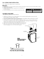
PROPER DISPOSAL OF YOUR OLD REFRIGERATION PRODUCT
DANGER
Suffocation Hazard
Remove doors from your old ice
machine.
Failure to do so can result in
child entrapment, which can
cause death or brain damage.
IMPORTANT: Child entrapment and suffocation are not problems of the past.
Junked or abandoned refrigeration products are still dangerous, even if they will
sit for “just a few days.” If you are getting rid of your refrigeration product,
please follow the instructions below to help prevent accidents.
BEFORE YOU THROW AWAY YOUR OLD REFRIGERATION PRODUCT:
•Take off the doors.
•Leave the shelves in place so that children may not easily climb inside.
41006471
Rev. E
GENERAL INFORMATION
Unpack
1. Remove banding from bottom of carton. Lift carton up and off of the ice machine
2. Remove all tape and packaging material from the outside and inside of the cabinet.
3. Keep all carton packaging until your ice machine has been thoroughly inspected and found to be in good
condition.
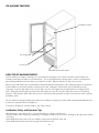
Area Requirements
1. Place unit so the front side will be completely unobstructed to provide proper air flow. The unit may be closed in
on the top and three sides, but the front MUST BE unobstructed for air circulation and proper operation.
Installation should be such that the cabinet can be moved for servicing if necessary.
2. Unit should be in a well ventilated area. Best results are obtained at temperatures between 550F (130C) and 800F
(270C) for built-in indoor models, between 550F (130C) and 900F (320C) for indoor freestanding models, and between
450F (7.20C) and 1100F (430C) for outdoor models.
3. Provisions for electricity should be determined before placing unit in proper place.
4. For best performance, outdoor units should be installed away from direct sunlight or under a counter or sink.
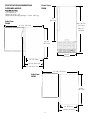
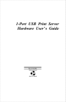
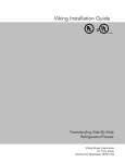
UNDERCOUNTER CABINET
CUTOUT
A
15” (38.1 cm)*
B
Min. 34 1/2” (87.6 cm)
A
Max. 35 1/8” (89.2 cm)
C
B
24” (61.0 cm)
*15” (38.1 cm) width for cabinet only. If door
is recessed between cabinets, cabinet cutout
must be 15-1/4” (38.7 cm.).
C
2
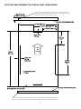
SPECIFICATIONS/DIMENSIONS
PROFESSIONAL MODELS
Front View
VUIM
Basic Electric Data
•115 VAC/60 Hz
•Maximum amps - 3.0
Approximate Shipping Weight - 110 lbs.
(49.5 kg)
Min. 34 1/4”
(87.0 cm)
26”
(66.0 cm)
Max. 35”
(88.9cm)
Side View
VUIM
14 3/4”
(37.5 cm)
37 9/16” (95.4 cm)
34 1/4”
(87.0 cm)
22” (55.9 cm)
24 5/8” (62.6 cm)
27 1/8” (68.9 cm)
3
SPECIFICATIONS/DIMENSIONS
DESIGNER MODEL
Front View
DUIM
Basic Electric Data
•115 VAC/60 Hz
•Maximum amps - 3.0
•Approximate Shipping Weight - 110 lbs. (49.5 kg)
26”
(66.0 cm)
Side View
DUIM
Min. 34 1/4”
(87.0 cm)
37 9/16” (95.4 cm)
Max. 35”
(88.9cm)
34 1/4”
(87.1 cm)
14 3/4”
(37.5 cm)
22” (55.9 cm)
24 5/8” (62.6 cm)
25 5/8” (65.1 cm)
37 9/16” (95.4 cm)
Side View
DFIM
34 1/4”
(87.1 cm)
22” (55.9 cm)
24 5/8” (62.6 cm)
4
FULL OVERLAY PANEL INSTALLATION
Note: Weight of wood panel must not exceed 20 lbs.
Wood Screws
1. A #8 pan head wood screw should be used to properly secure the wood panel. A total of 8 screws will be needed.
2. Only use pan head screws.
3. DO NOT select a screw that is longer than the wood thickness at
Working Material
Wood Screw Size #8
the screw locations.
Hardwood
3/32 (0.24 cm)
4. Use recommended pilot holes for the frame material. (See chart)
Softwood
5/64 (0.20 cm)
Assembling Door Hinge Brackets
(Disregard if hinge brackets are already attached)
1. Attach the top and bottom door hinge brackets to the door with the #10-32 machine screws and a 1/8”
allen head driver as shown in Figure 1 below.
2. Press in the shoulder bushings to the top and bottom door hinge brackets. Make certain that the shoulder
is to the outside of the door as shown in Figure 1 below.
3. Test fit the door to the unit to make certain door will hang correctly. The door is hung correctly when the
top of the door is parallel to the top of the unit. Adjustments can be made by loosening the door hinge
machine screws and moving the door hinge brackets on the door.
4. Tighten all four (4) machine screws after adjustments have been made.
Shoulder Bushing
5. Remove the door from the unit by removing the units top hinge set
screw and angling the door off of the bottom hinge pin.
Door Hinge Bracket
#10-32 Machine
Screw
Door Hinge
Screw Holes
FIGURE 1
Typical Top and Bottom Door
Hinge Bracket Assembly
FRONT
Bottom View of Door with Left Hand Swing
5
Door Front
Surface
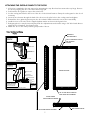
SELECTING AND PREPARING THE OVERLAY PANEL (DFIM MODELS)
1/4” x 3/8” Deep hinge screw clearance hole. Locate and drill
using door hinge hole after the door has been aligned to the unit
and when the wood is positioned on door.
Min. 5/8” (1.7 cm)
Max. 3/4” (1.9 cm)
Mounting surface (non-face) side
14 3/4” (37.5 cm)
8 15/16” (22.7 cm) TYP
5 13/16” (14.8 cm)
23/32 “ TYP
(1.8 cm))
5”
(12.7 cm)
TYP
TOP
OF
DOOR
25 5/8”
(65.1 cm)
13/16” TYP
(2.1 cm)
Both Sides
19 3/16”
(48.7 cm)
TYP
Pre-drilled pilot holes
8 places
Mounting surface (non-face) side
Mounting surface (non-face) side
1/4” x 3/8” Deep hinge screw clearance hole. Locate and drill using door hinge hole
after the door has been aligned to the unit and when the wood is positioned on door.
6
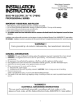
ATTACHING THE OVERLAY PANEL TO THE DOOR
1. If the door is attached to the unit, remove by unscrewing the top allen head set screw at the top hinge. Remove
the door by angling the door off of the bottom hinge pin.
2. Peel back the door gasket to expose the screw holes.
3. Set the overlay panel flush to the front of the door in the desired location. Clamp the overlay panel to the door if
necessary.
4. Insert the wood screws through the back of the door into the pilot holes in the overlay panel and tighten.
5. Reinstall the door gasket by pressing into the door channel. Make certain the corners are inserted fully.
6. Install the door to the unit. Use the supplied plastic washer as shown in the figure below.
7. Realigning the door may be necessary. Any final door adjustments can be made using a 1/8” allen head driver to
adjust the door’s brackets. (See figure below)
8. Attach the door to the unit by reversing step number 1 above.
Hinge Hardware Installation
Details
CAUTION
DOOR CAN BECOME
DISENGAGED IF
WASHERS ARE
NOT INSTALLED
MAGNETIC
DOOR GASKET
(2) NYLON
HARDWARE
COMPONENTS
AT TOP HINGE
0Ø0.38
3/8” CLEARANCE
CLEARANCEHOLES
HOLES
FOR
FOR SCREWS
SCREWS
88 HOLES
HOLES
.625 OD X .218 ID
WASHER
SHOULDER BUSHING
DOOR HINGE
BUSHING BRACKET
OVERLAY PANEL
TOP HINGE CORNER
CAUTION
DOOR CAN BECOME
DISENGAGED IF
WASHERS ARE
NOT INSTALLED
REFRIGERATOR
DOOR
REAR OF DOOR
OVERLAY PANEL
DOOR HINGE
BUSHING BRACKET
SHOULDER BUSHING
.75 OD X .443 ID
WASHER
.75 OD X .257 ID
WASHER
CAUTION
DOOR MAY NOT SWING
PROPERLY IF ALL NYLON
COMPONENTS ARE NOT
INSTALLED AS SHOWN
(3) NYLON
HARDWARE
COMPONENTS
AT BOTTOM
HINGE
BOTTOM HINGE CORNER
1/8”
ALLEN
HEADHEAD
SCREWS
1/8 INCH
ALLEN
SCREWS
FOR HINGE ADJUSTMENT
DOOR HINGE
ADJUSTMENT SCREWS
ATTACHED OVERLAY PANEL
7
BOTTOM OF DOOR
LEG LEVELER INSTALLATION
READ BEFORE INSTALLING LEG LEVELERS
WARNING
Do not lay unit on top, side, back, or front. If unit is accidentally laid in any position other than right side up, then the
unit must remain in the right side up position for at least 24 hours before plugging the unit in.
1. Tip unit backwards so there is (1) foot of clearance on front of the unit. Have someone to assist you in tilting the
unit, to prevent it from falling on you while installing the leg levelers.
2. Screw front two leg levelers into the screw impressions. Leg levelers should be screwed in until snug.
3. Repeat steps 1 & 2, with the exception of tipping the unit forwards now, to screw in the back two leg levelers.
4. Your leg levelers are now installed.
5. The unit should be level from front to back and side to side. If floor conditions do not allow the unit to sit level,
adjust leg leveler(s) by turning the required leg leveler(s) counter-clockwise to increase their height and clockwise to
reduce their height.
Screw
Impressions
8
ELECTRICAL CONNECTION
WARNING
ELECTRICAL SHOCK HAZARD
Failure to follow these instructions could result in fire or electrical shock.
Electrical Requirements
A 115 volt, 60 Hz, AC only 15 amp fused electrical supply is required. (A time delay
fuse or circuit breaker is recommended.) It is recommended that a separate circuit,
serving only this appliance, be provided.
•ELECTRICAL GROUND IS REQUIRED ON THIS APPLIANCE.
•DO NOT UNDER ANY CIRCUMSTANCES REMOVE THE POWER
SUPPLY CORD GROUND PLUG.
•DO NOT USE AN EXTENSION CORD.
Grounding type wall
receptacle
Power Supply
with 3-prong
grounding plug
Recommended Grounding Methods
For your personal safety, this refrigeration product must be grounded. This appliance is equipped with a 5’ power supply cord
having a 3-prong grounding plug. To minimize possible shock hazard, the cord must be plugged into a mating 3-prong
grounding type wall receptacle grounded in accordance with the National Electrical Code and local codes and ordinances. If
the circuit does not have a grounding type receptacle, it is the responsibility and obligation of the customer to exchange the
existing receptacle in accordance with the National Electrical Code and applicable local codes and ordinances. The third
ground plug SHOULD NOT, under any circumstances, be cut or removed. All UL listed refrigerated products are equipped
with this type of plug.
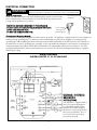
WIRING DIAGRAM
UNDERCOUNTER 15” W. ICE MACHINE
WARNING: ELECTRICAL
GROUNDING
INSTRUCTIONS
This appliance is equipped with a
three prong grounding plug for
your protection against shock
hazard and should be plugged
directly into a properly grounded
three prong receptacle. Do not
cut or remove the grounding
prong from this plug.
9
WATER CONNECTION
REAR OF UNIT
GARDENHOSE
FITTING
5/8" (.63 cm) I.D. DRAIN
TUBING BARB
MAKE CERTAIN ALL HOSE
CLAMPS ARE SECURE
5 1/2" (14.0 cm)
1/4" (.64 cm) TUBING FROM
COLD WATER LINE
2 1/8" (5.4 cm)
COMPRESSIONFITTING
Water Supply
•This ice machine must be connected to a potable, active cold water supply line delivering water pressure at a minimum
pressure of 20 psi and maximum of 120 psi.
•Water connection is made through a 1/4” (.64 cm) compression right angle garden hose fitting. Do not use any thread
sealers. NOTE: The water line fitting supplied with your ice machine is to be used on a 1/4” (.64 cm) copper water supply
line only. Do not attach a plastic supply line to your unit using this fitting.
Rubber washer
Adapter
Fitting valve
1/4” (.64 cm) copper
water supply line
(supplied by customer)
Compression fitting
From water supply
to ice machine
Compression nut
•A water filter is recommended for this unit. A quality filter can remove particles as well as remove taste and odors from water.
•Do not use a reverse osmosis water filtration system with the ice machine.
Softened water is not recommended. This will produce mushy, cloudy ice cubes that will stick together.
•S
De-ionized water is not recommended. This water will not form solid ice cubes.
•D
•A water specialist can recommend proper water treatment.
•After installation of water line, turn on water and check for any leaks. Additional tightening may be needed. Do not use any
type of thread sealer.
•Allow extra water line for easy removal of unit and to help prevent the water line from kinking.
10
DRAIN PLUMBING
WARNING
Your ice machine uses a gravity drain that requires 5/8” (.63 cm) ID tubing from the back of the
ice maker to a plumbed connection to a sanitary sewer (see Gravity Drain drawing below).
Remove the access panel, with a 5/16” (0.8 cm) wrench to plumb in drain connection. Gravity
drain location for built-in units can be within the area shown in illustration below. An optional
drain pump can be purchased for your ice machine if a gravity drain is not accessible.
Observe and follow all local codes when installing an ice machine.
Failure to use adequate
drainage system will result
in surrounding water
damage and/or poor ice
production.
GRAVITY DRAIN LOCATION
GRAVITY DRAIN
24 5/8” (62.6 cm)
22” (55.9 cm)
Front of
Unit
Top of
Unit
6 3/4”
(17.1 cm)
14 3/4”
(37.5 cm)
2 3/8” (6.0 cm)
4 1/16”
(10.3 cm)
5/8" (.63 cm) I.D.
DRAIN TUBING
AND HOSE CLAMP
1 1/2" (3.8 cm) DRAIN
PIPE
ACCESS PANEL
DRAIN TRAP
DRAIN FROM
ICE MAKER
ICE MAKER
POWER CORD
DRAIN PUMP
Model Number - VUIM-DP
(Sold separately - see installation
instructions supplied with drain
pump)
TUBING CLAMPS
VENT TUBE
SUPPLIED SCREWS
DISCHARGE TUBE GOES THRU
THIS OPENING IN THE ACCESS PANEL
DRAIN FROM
ICE MAKER
DRAIN PUMP
ACCESS PANEL
DRAIN PUMP
POWER CORD
VENT TUBE
GOES
THRU
OPENING
VENT
TUBE
GOESTHIS
THRU
THIS
THE
ACCESS
PANEL
OPENING}{ ININ
THE
ACCESS
PANEL
11
DRAIN
PUMP’S DISCHARGE
DRAIN PUMP'S}{
DISCHARGE
LINE
THRU THIS
LINE THRU}{
THIS OPENING
OPENING
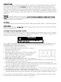
ICE MACHINE FEATURES
Escutcheon Panel
Ice Storage Bin
Ice Scoop
On/Off/Clean Rocker Switch
HOW THE ICE MACHINE WORKS
Your ice machine is unique in forming ice. It uses fractional freezing to form a slab of ice that is clear and has less
mineral content than the water it is produced from. This is accomplished by running water over the cold evaporator
plate which gradually freezes the water to produce the ice slab. Mineral deposits are left in the reservoir.
When the ice slab reaches the correct thickness determined by the temperature of the evaporator plate, the electronic
control switches to the harvest cycle to harvest the ice slab. During the harvest cycle, the ice slab falls from the
evaporator to the ice grid cutter. Here, the ice slab is cut into 3/4” squares by the grid cutter’s low voltage heated
wires. During the harvest cycle, the drain valve will remain open for 45 seconds to drain the reservoir of remaining
deposits. After that, the water valve will open for 2 minutes providing 2 quarts of water to the reservoir for the next ice
production cycle.
The ice machine will keep producing ice until the ice machine’s storage bin is full and will restart automatically when ice
needs to be replenished in the storage bin.
To begin ice production, turn the switch to the “ON” position.
Ice Machine Safety and Operation Tips
•Avoid leaning on the cabinet door. You may bend the door hinge or tip the unit.
•Exercise caution when sweeping, vacuuming, or mopping near the front of the unit. Damage to the grill and/or switch
can occur.
•Periodically clean the inside of the ice machine components and inside of the unit.
•Periodically check and/or clean the front grill and condenser coils.
12
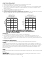
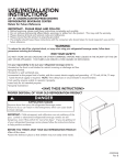
USING YOUR ICE MACHINE
PRODUCTION
RATE (LB/DAY)*
WATER TEMPERATURE 0F
APPROXIMATE
TIME TO FILL BIN (HOURS)*
WATER TEMPERATURE 0F
50
70
50
70
70
33
32
70
31
34
80
30
27
80
41
58
90
23
20
90
60
82
100
17
13
100
85
∞**
ROOM
TEMPERATURE 0F
ROOM
TEMPERATURE 0F
1. Allow your ice machine to run for at least 48 hours to accumulate ice in the ice bin.
2. The unit will cycle off between ice production and ice harvest cycles.
3. Your ice machine will make unusual noises that you do not normally hear form your household refrigerator/freezer.
These noises do not mean your ice machine is not functioning properly. They occur as a normal part of the ice
machine’s operations.
4. The unit will automatically shut down when the ice bin is full.
5. Unplug the ice machine before working on the unit.
6. Keep the ice machine clean for proper ice quality, production, and unit life.
7. Room and water supply temperatures will greatly affect the output of ice in the unit. (See table below.) Ice will also
melt away, especially at the start of an empty bin, but will slow down as ice accumulates.
*NOTE: Due to variables in installation and use, individual results may vary.
**Continuous run, bin will fill significantly, but heat flow and water temperature do not
allow ice bin to fill to shut-off thermistor.
Outdoor Use
1. For best performance, install under a counter or shelter. Avoid direct sunlight.
2. If the ice machine is not used for an extended period of time or if temperatures are below 450F (7.20C), it is
necessary to remove remaining water in the ice making system. (See Preparing Ice Machine for Storage, p. 12).
3. Chlorine gas from swimming pools and spas may discolor stainless steel. (See Cleaning and Maintenance below for
instructions on cleaning).
CLEANING AND MAINTENANCE
Any piece of equipment works better and lasts longer when maintained properly and kept clean.
Condenser
The condenser tubing inside the cabinet does not require frequent cleaning; however, satisfactory cooling depends on
adequate ventilation over the coils. Be sure that nothing obstructs the required air flow openings in front of the cabinet.
Spiders and insects can nest in and around the ice machine causing damage to the unit. Frequently brush or vacuum
(twice yearly) lint and dirt from the condenser for efficient performance by unscrewing the grill and kickplate on the
bottom front of cabinet.
Cabinet
The cabinet can be washed with mild soap and water and thoroughly rinsed with clear water. Never use abrasive scouring
powders.
Interior/Ice Scoop
Wash interior compartment and ice scoop with mild soap and water or a baking soda and water solution. Do not use
abrasive powder, solvent, polish cleaner or undiluted detergent.
13
Stainless Steel Parts
All stainless steel parts should be wiped regularly with hot soapy water. Use a liquid cleaner designed for stainless steel
when soapy water will not do the job. Do not use bleach, steel wool, abrasive cloths, cleansers, or powders. Do not
permit citrus or tomato juice to remain on stainless steel surfaces, as citric acid will permanently discolor stainless steel.
Note: Under rare conditions, such as an extremely salty environment, small amounts of rust may accumulate on stainless
steel parts. These small amounts of surface rust can easily be removed by apply Soft Scrub® Gel to a damp sponge and
wiping with the stainless steel grain. It is important to make sure you wipe with the grain for the most efficient removal of
surface rust.
Brass Parts
CAUTION: All brass parts have an epoxy coating. DO NOT USE BRASS OR ABRASIVE CLEANERS ON THE BRASS
PARTS. All brass parts should be wiped regularly with hot soapy water. When hot soapy water will not do the job, use
every day non-abrasive household cleaners.
Door Gasket
The vinyl gasket may be cleaned with mild soap and water, a baking soda and water solution, or a mild scouring powder.
Painted Surfaces
Wash with warm soapy water. DO NOT USE steel wool, abrasive cleansers, ammonia, acids or commercial oven cleaners
which may damage the finish.
CLEANING THE ICE MACHINE SYSTEM
Some impurities will remain and buildup in the ice machine and stick to the ice machine’s parts over time. This buildup must be removed for proper ice production, ice quality, and ice machine life. Your ice machine is equipped with a
cleaning mode that will help in cleaning out these impurities.
WARNING
Read and follow manufacturer’s warnings on ice
machine cleaner products.
The ice machine will regularly (at the very least, annually) need to be cleaned of this build-up, depending on use and
water hardness. You can use an acid such as one specified for ice machine cleaning or you can use citric acid to
remove the build-up. To clean the ice machine:
1. Switch the selector switch to the “OFF” position.
2. Remove the drain plug at the bottom of the reservoir to drain any
remaining water and then reinstall.
3. Remove the escutcheon panel.
4. Add cleaning solution to the reservoir. NOTE: Three quarts of water
will automatically be added to the reservoir. Therefore, cleaning
solution should not be diluted. Please follow manufacturer’s
instructions for mixing with 3 quarts of water.
5. Replace escutcheon panel and close door.
6. Switch selector switch on the grill of the machine to the clean position.
7. The cleaning cycle will end in 49 minutes. The cleaning cycle will automatically rinse the evaporator plate, drain
the cleaning solution, and rinse the components.
8. After the cleaning cycle has ended, remove the escutcheon panel again and check that build-up has been
removed. The evaporator plate should be clean, shiny, and smooth to the touch. If not and build-up is still visible,
repeat the cleaning cycle above. If build-up is removed, continue below.
9. Remove the distributor tube, hose clamp, hose and its rubber ends.
10. Thoroughly clean the inside of the distributor tube and the spray holes. You can use the same cleaning solution as
before and an old tooth brush to reach the inside of the distributor tube.
11. Reinstall the rubber end, hose, and hose clamp to the distributor tube and then reinstall the distributor tube to the
evaporator with the spray holes pointed to the bottom of the evaporator plate. Reinstall the escutcheon panel.
Your ice machine is now clean and sanitized. It can be placed back into operation by switching the selector switch to
the “ON” position. Please wait 48 hours for maximum ice production.
14
PREPARING THE ICE MACHINE FOR
STORAGE
If the ice machine is moved, not used for an extended
period of time, or will be in a area below 45oF (7.2oC), it
is necessary to remove the water from the ice making
system.
CAUTION
This ice machine must have all water drained and removed
to prevent ice machine damages as well as possible water
damage to the surrounding area in freezing conditions.
These damages are not covered under warranty.
WARNING
Do not use any type of anti-freeze or other solutions as a
Step 1: Clean the ice machine (refer to page 11.)
s
ubstitution for properly draining the ice machine.
Step 2: Drain and remove water from ice making system.
1. Turn off the water supply to the ice machine.
2. Disconnect the water supply fitting at the inlet of the water valve.
3. Switch the rocker switch to “CLEAN” for approximately 1 minute. This will energize and open the water valve
and remove most of the water from the water valve and the water valve’s outlet water line to the reservoir.
4. Switch the rocker switch to “OFF”. This will energize and open the drain valve to drain the reservoir and the
ice machine drain system.
5. Unplug the unit from the electrical outlet.
6. Remove the back panel from the rear of the unit.
7. Disconnect the water valve’s outlet water line to the reservoir and drain the remaining water left in the water
line trap area.
8. Reconnect the water valve outlet water line and tighten the compression nut to a watertight seal.
9. Reinstall the unit’s back panel.
10. Clean and dry the ice machine’s storage bin.
11. Prop the door open for air circulation to prevent mold and mildew.
12. Leave the water supply line disconnected or reconnect the supply line and leave it shut off. DO NOT turn the
water and allow water to enter back into the water valve.
STEP 3: Drain water from optional drain pump, if applicable.
1. Remove the drain pump from the ice machine. (Refer to drain pump installation instructions).
2. Drain the water in the drain pump’s reservoir by running the pump upside down and allowing water to drain
through the pump’s inlet and vent tube fittings.
3. After all water is drained, reinstall the drain pump. Make certain all tubing is installed and all hose clamps are
tight. (Refer to drain pump installation instructions).
Step 4: Restart the ice machine when ready for use.
1. With the rocker switch in the “OFF” position, plug the unit into an electrical outlet.
2. Reconnect or turn on the water supply line.
3. Reconnect drain tubing if removed.
4. Turn the rocker switch to the “ON” position.
5. Check the water inlet, drain lines, and fittings for any water leaks.
6. Check drain pump, (if applicable), operation by pouring approximately 2 quarts (1.9 L) of water into the ice
storage bin. The drain pump should activate and discharge water. (Refer to drain pump installation
instructions). Check for water leaks at all hose connections.
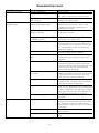
TROUBLESHOOTING GUIDE
PROBLEM
Water keeps backing up
into ice bin (drain pump).
POSSIBLE CAUSE
Drain pump tubing kinked or
restricted
Inlet screen to the drain pump is
restricted.
Drain pump and/or the ice machine
are not level.
The drain pump cycles on Vent line to the drain pump is
and off erratically.
restricted or kinked.
Discharge line is restricted or kinked.
The drain pump is not level.
15
CORRECTION
Check inlet, discharge, and vent line tubing for
any kinks or restrictions and repair as needed.
Clean the inlet screen to the drain pump.
Check and level the drain pump and the
ice machine if necessary.
Check the vent line for any restrictions or kinks
and repair as needed.
Check the discharge line and connection to the desired
drain for any restrictions or kinks and repair as needed.
The drain pump must be level. Check for level on the
top of the drain pump case and adjust the tubing or use
shims to level.
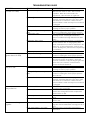
TROUBLESHOOTING GUIDE
PROBLEM
Unit does not operate.
Unit operates but does not
produce any ice.
POSSIBLE CAUSE
The unit is unplugged
Breaker is tripped or fuse is blown.
Ice machine selector switch is in the
“OFF” position.
The unit has just been started and
it has been less than 6 hours.
Typical ice production cycle can
take up to 1.5 hours.
The selector switch is in the “OFF”
or “CLEAN” position.
No water in the reservoir.
Distributor tube is restricted.
Build-up of deposits on evaporator
plate.
Condenser fan air flow is restricted
Room and/or water temperature
is too warm.
Leaking drain valve
Inadequate drain system
Grid cutter is unplugged
Ice is not clear
Low water in level in reservoir.
Softened water supply
Room temperature it too cold.
16
CORRECTION
Plug in the unit.
Reset breaker or replace fuse. Check to make
sure there is not a short in the electrical circuit.
Set the rocker switch on the grill of the
machine to the “ON” position.
Ice produced when the unit is initially
started will melt off in the bin. This is normal
operation. Check the unit in 24 hours for ice
accumulation in the bin.
Check the unit in 24 hours for ice
accumulation in the bin.
Set the rocker switch on the grill of the
ice machine to the “ON” position.
Make sure that the reservoir drain plug is installed.
Check the water line to the unit to make sure it is
on and that there are no restrictions or kinks in the
line. Check all filters to make sure they are not
restricted or plugged.
See “Cleaning the Ice Machine System” section for
cleaning the unit for proper operation.
See “Cleaning the Ice Machine
System” section for cleaning the unit for proper
operation.
Make certain the grill in the front of the unit is free
and open for proper air circulation. Check and
clean the condenser coil by removing the grill in the
front of the unit. Clean the condenser with a
vacuum and brush attachment.
Move the unit to an area where
ambient temperature is below 90oF. The unit should
not be placed next to a heat source such as an
oven. Check for cold water connection.
See “Cleaning the Ice Machine System” section for
cleaning the unit. This will also dissolve and flush
out foreign material in the drain valve.
Restriction in drain lines will cause ice in the bin to
melt. If using a gravity drain, make certain there are
no kinks or restrictions in the drain lines. If using a
drain pump, check the inlet screen, discharge line,
and vent line for any build-up or restrictions.
Plug in the grid cutter so that ice slabs can be cut
into cubes.
Make sure that the reservoir drain plug is installed
properly. Check the water line to the unit to make
sure there are no restrictions or kinks in the line.
Check all filters to make sure they are not restricted
or plugged.
Make certain that water line is not connected to the
water softener.
Move to an area where room temperature is above
55oF.
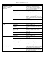
TROUBLESHOOTING GUIDE
PROBLEM
Ice cubes are too small
(less than 1/2” thick)
POSSIBLE CAUSE
Low ice consumption
CORRECTION
Not enough water in reservoir.
Distributor tube is restricted.
Build-up of deposits on evaporator
plate.
Leaking drain valve
Inadequate drain system.
Ice cubes are too big
(greater than 3/4” thick)
Room temperature is too warm.
Ice slab not releasing.
Condenser fan air flow is restricted.
Hollow ice slab
Room temperature is too warm.
Distributor tube is restricted.
Build-up of deposits on evaporator
plate.
Low water level in reservoir.
Unit continues to run
and produce ice.
Ice bin is not full.
Ice bin is full.
Room temperature is too warm.
Ice machine is not level.
Ice cubes are sticking
together.
Ice consumption is low.
Room temperature is too warm
17
Ice is slowly melting in the ice bin and will
affect the size of the ice cube. This is normal
operation. When the ice bin needs to be
replenished, cubes will return to regular size.
Make sure that the reservoir drain plug is installed
properly. Check the water line to the unit to make
sure there are no restrictions or kinks in the line.
Check all filters to make sure they are not restricted
or plugged.
See “Cleaning the Ice Machine System” section for
cleaning the unit for proper operation.
See “Cleaning the Ice Machine System”
section for cleaning the unit for proper operation.
See “Cleaning the Ice Machine System” section for
cleaning the unit. Cleaning the unit will also
dissolve and flush out foreign material in the drain
valve.
Restriction in drain lines will cause ice in the bin to
melt to a thinner cube. If using a gravity drain,
make certain there are no kinks or restrictions in the
drain lines. If using a drain pump, check the inlet
screen, discharge line, and vent line for any build-up
or restrictions.
Move to an area where temperature is below 90oF.
See “Cleaning the Ice Machine System”
section for cleaning the unit for proper operation.
Make certain the grill in the front of the unit is free
and open for proper air circulation. Check and
clean the condenser coil by removing the grill in the
front of the unit. Clean the condenser with a
vacuum and brush attachment.
Move to area where temperature is below 90oF.
See “Cleaning the Ice Machine System” section for
cleaning the unit for proper operation.
See “Cleaning the Ice Machine System”
section for cleaning the unit for proper operation
and cube size.
Make sure that the reservoir drain plug is installed
properly. Check the water line to the unit to make
sure there are no restrictions or kinks in the line.
Check all filters to make sure they are not restricted
or plugged.
The unit will automatically shut down when
ice reaches the sensing tube.
The unit will automatically shut down when ice
reaches the sensing tube and has completed the
harvest of the ice slab.
Move to an area where room temperature is below
90oF.
Use a level to check the unit from side to side and
front to rear.
Use the ice in the bin frequently. Ice will stick
together if left in insulated bin over long periods of
time.
Move the unit to an area where temperature is
below 90oF.
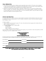
TROUBLESHOOTING GUIDE
PROBLEM
Low ice production. Unit
is running, has run over a 48
hour period, and there is
little ice in bin.
POSSIBLE CAUSE
Low water level in reservoir.
Distributor tube is restricted.
Build-up of deposits on evaporator
plate.
Inadequate drain system.
Condenser fan air flow is restricted
Grid cutter is not cutting
ice slab.
The selector switch is not in the
“ON” position.
The grid cutter is not plugged into
receptacle.
It has not had time to cut
through the slab.
Ice level is too low.
The ice machine is not level
Room temperature is too cold.
Ice level is too high.
The selector switch is not in the
“ON” position.
The ice machine is not level
Room temperature is too warm.
Ice deflector is not in place or
secured properly.
Bin level sensing tube needs
adjusting.
Water keeps backing up
into ice bin (gravity drain).
Inadequate drain system.
Foreign material in ice bin drain
18
CORRECTION
Make sure that the reservoir drain plug is
installed properly. Check the water line to
the unit to make sure there are no restrictions
or kinks in the line. Check all filters to make sure
they are not restricted or plugged.
See “Cleaning the Ice Machine System” section for
cleaning the unit for proper operation.
See “Cleaning the Ice Machine System”
section for cleaning the unit for proper operation.
Restriction in drain lines will cause ice in the bin to
melt to a thinner cube. If using a gravity drain,
make certain there are no kinks or restrictions in the
drain lines. If using a drain pump, check the inlet
screen, discharge line, and vent line for any build-up
or restrictions.
Make certain the grill in the front of the unit is free
and open for proper air circulation. Check and
clean the condenser coil by removing the grill in the
front of the unit. Clean the condenser with a
vacuum and brush attachment.
Set the rocker switch on the grill of the ice
machine to the “ON” position.
Remove the escutcheon panel and plug the
grid cutter into the receptacle on the side of the
liner.
It can take up to 35 minutes to cut through a
harvested ice slab. This is normal operation.
Use a level to check the unit from side to side and
front to rear.
Move the unit to an area where temperature is
above 55oF.
Set the rocker switch on the grill of the ice
machine to the “ON” position.
Use a level to check the unit from side to side and
front to rear.
Move the unit to an area where temperature is
below 90oF.
Check to see that the ice deflector is in place
and secured below the grid cutter.
Adjust the bin level sensing tube by simply
pressing directly down on the tube 5 inches from
the front of the tube to get a desired bin level.
Restriction or improperly installed drain lines
will cause water to back up into the ice bin. Make
certain there are no kinks or restrictions in the drain
lines. If necessary, consult a qualified plumber.
Foreign material is restricting or blocking the ice bin
drain located at the right rear corner of the ice bin.
The drain will need to be cleared.
FINAL PREPARATION
1. Some stainless steel parts may have a plastic protective wrap which must be peeled off. The interior of the ice machine
should be washed thoroughly with hot, soapy water, rinsed and wiped dry to remove film residue and any installation dust
or debris before being used. Solutions stronger than soap and water are rarely needed.
2. All stainless steel parts should be wiped with hot soapy water. If buildup occurs, do not use steel wool, abrasive cloths,
cleaners, or powders. If it is necessary to scrape stainless steel to remove encrusted materials, soak with hot, wet cloths to
loosen the material, then use a wood or nylon scraper. Do not use a metal knife, spatula, or any other metal tool to scrape
stainless steel; scratches are almost impossible to remove.
SERVICE INFORMATION
It is assumed that your ice machine has been properly installed in accordance with all specifications and local codes and
the appliance has been properly grounded. If your ice machine should fail to operate, review the troubleshooting chart
before calling for service.
If service is required:
1. Call your dealer or authorized service agency. The name of the authorized service agency can be obtained from the
dealer or distributor in your area.
2. Have the following information readily available:
•Model number
•Serial number
•Date of purchase
•Name of dealer from whom purchased
If you are unable to obtain the name of an authorized service agency, or if you continue to have service problems, contact
Viking Range Corporation at (888) 845-4641 or write to:
VIKING RANGE CORPORATION
PREFERRED SERVICE
111 Front Street
Greenwood, Mississippi 38930 USA
Record the following information indicated below. You will need it if service is ever required. The serial number and
model number for your ice machine is located on the front of the unit at the base of the door frame.
Model Number
Serial Number
Date of Purchase
Date Installed
Dealer’s Name
Address
If service requires installation of parts, use only authorized parts to ensure protection under the warranty.
This manual should remain with the ice machine for future reference.
19
UNDERCOUNTER/FREESTANDING ICE MACHINE WARRANTY
(Units certified for Indoor Use)
TWO YEAR FULL WARRANTY
Undercounter/freestanding ice machines and all of their components and accessories, except as detailed below*, are warranted to be free from defects in material or
workmanship under normal household use for a period of two (2) years from the date of original retail purchase. Viking Range Corporation, warrantor, agrees to repair
or replace, at its option, any part which fails or is found to be defective during the warranty period
*Painted and decorative items are warranted to be free from defective materials or workmanship for a period of ninety (90) days from the date of original retail
purchase. ANY DEFECTS MUST BE REPORTED TO THE SELLING DEALER WITHIN NINETY (90) DAYS FROM DATE OF ORIGINAL RETAIL PURCHASE.
SIX YEAR FULL WARRANTY
Any sealed refrigeration system component, as listed below, is warranted to be free from defective materials or workmanship in normal household use during the third
through the sixth year from the date of original retail purchase. Viking Range Corporation, warrantor, agrees to repair or replace, at its option, any part which fails or is
found to be defective during the warranty period.
Sealed Refrigeration System Components:
Compressor, Evaporator, Condenser, Connecting Tubing, Dryer/Strainer
TWELVE YEAR LIMITED WARRANTY
Any sealed refrigeration system component, as listed above, which fails due to defective materials or workmanship in normal household use during the seventh
through the twelfth year from the date of original retail purchase will be repaired or replaced, free of charge for the part itself, with the owner paying all other costs,
including labor.
NINETY (90) DAY RESIDENTIAL PLUS WARRANTY This warranty applies to applications where use of the product extends beyond normal residential use.
Examples are, but not limited to, bed and breakfasts, fire stations, private clubs, churches, etc. This warranty excludes all commercial locations such as
restaurants, food service locations and institutional food service locations.
This warranty extends to the original purchaser of the product warranted hereunder and to each transferee owner of the product during the term of the warranty.
This warranty shall apply to products purchased and located in the United States and Canada. Products must be purchased in the country where service is requested.
Warranty labor shall be performed by an authorized Viking Range Corporation service agency or representative. Warranty shall not apply to damage resulting from
abuse, accident, natural disaster, loss of electrical power to the product for any reason, alteration, improper installation, improper operation or repair or service to the
product by anyone other than an authorized Viking Range Corporation service agency or representative. Warranty shall not apply to damage resulting from indoor
units being used in outdoor situations. This warranty does not apply to commercial usage. Warrantor is not responsible for consequential or incidental damage
whether arising out of breach of warranty, breach of contract, or otherwise. Some jurisdictions do not allow the exclusion or limitation of incidental or consequential
damages, so the above limitation or exclusion may not apply to you.
Owner shall be responsible for proper installation, providing normal care and maintenance, providing proof of purchase upon request, and making the appliance
reasonably accessible for service. If the product or one of its component parts contains a defect or malfunction during the warranty period, after a reasonable number
of attempts by the warrantor to remedy the defects or malfunctions, the owner is entitled to either a refund or replacement of the product or its component part or
parts. Replacement of a component part includes its free installation. Warrantor’s liability on any claim of any kind, with respect to the goods or services covered
hereunder, shall in no case exceed the price of the goods or service or part there of which gives rise to the claim.
WARRANTY SERVICE: Under the terms of this warranty, service must be performed by a factory authorized Viking Range Corporation service agent or representative.
Service will be provided during normal business hours, and labor performed at overtime or premium rates shall not be covered by this warranty. To obtain warranty
service, contact the dealer from whom the product was purchased, an authorized Viking Range Corporation service agent, or Viking Range Corporation. Provide
model and serial number and date of original purchase. For the name of your nearest authorized Viking Range Corporation service agency, call the dealer from whom
the product was purchased or Viking Range Corporation. IMPORTANT: Retain proof of original purchase to establish warranty period.
The return of the Owner Registration Card is not a condition of warranty coverage. You, however, should return the Owner Registration Card so that Viking Range
Corporation can contact you should any question of safety arise which could affect you.
Any implied warranties of merchantability and fitness applicable to the above described undercounter ice machine are limited in duration to the period of coverage of
the applicable express written limited warranties set forth above. Some jurisdictions do not allow limitations on how long an implied warranty lasts, so the above
limitation may not apply to you. This warranty gives you specific rights, and you may also have other rights which may vary from jurisdiction to jurisdiction.
20
UNDERCOUNTER/FREESTANDING ICE MACHINE WARRANTY
(Units certified for Outdoor Use)
ONE YEAR FULL WARRANTY
Undercounter/freestanding ice machines and all of their components and accessories, except as detailed below*, are warranted to be free from defects in material or
workmanship under normal household use for a period of one (1) year from the date of original retail purchase. Viking Range Corporation, warrantor, agrees to repair or
replace, at its option, any part which fails or is found to be defective during the warranty period.
*Painted and decorative items are warranted to be free from defective materials or workmanship for a period of ninety (90) days from the date of original retail purchase.
ANY DEFECTS MUST BE REPORTED TO THE SELLING DEALER WITHIN NINETY (90) DAYS FROM DATE OF ORIGINAL RETAIL PURCHASE.
FIVE YEAR LIMITED WARRANTY
Any sealed refrigeration system component, as listed below, is warranted to be free from defective materials or workmanship in normal household use during the second
through the fifth year from the date of original retail purchase. Viking Range Corporation, warrantor, agrees to repair or replace, at its option, any part which fails or is found
to be defective during the warranty period.
Sealed Refrigeration System Components:
Compressor, Evaporator, Condenser, Connecting Tubing, Dryer/Strainer
It is recommended that in temperatures above 110oF (43.0oC) and below 45oF (7.2oC) the unit be shut off. The normal operating range for the unit is between 45oF (7.2oF)
and 110oF (43.0oC).
NINETY (90) DAY RESIDENTIAL PLUS WARRANTY This warranty applies to applications where use of the product extends beyond normal residential use.
Examples are, but not limited to, bed and breakfasts, fire stations, private clubs, churches, etc. This warranty excludes all commercial locations such as restaurants,
food service locations and institutional food service locations.
This warranty extends to the original purchaser of the product warranted hereunder and to each transferee owner of the product during the term of the warranty.
This warranty shall apply to products purchased and located in the United States and Canada. Products must be purchased in the country where service is requested.
Warranty labor shall be performed by an authorized Viking Range Corporation service agency or representative. Warranty shall not apply to damage resulting from abuse,
accident, natural disaster, loss of electrical power to the product for any reason, alteration, improper installation, improper operation or repair or service to the product by
anyone other than an authorized Viking Range Corporation service agency or representative. Warranty shall not apply to damage resulting from indoor units being used in
outdoor situations. This warranty does not apply to commercial usage. Warrantor is not responsible for consequential or incidental damage whether arising out of breach
of warranty, breach of contract, or otherwise. Some jurisdictions do not allow the exclusion or limitation of incidental or consequential damages, so the above limitation or
exclusion may not apply to you.
Owner shall be responsible for proper installation, providing normal care and maintenance, providing proof of purchase upon request, and making the appliance reasonably
accessible for service. If the product or one of its component parts contains a defect or malfunction during the warranty period, after a reasonable number of attempts by
the warrantor to remedy the defects or malfunctions, the owner is entitled to either a refund or replacement of the product or its component part or parts. Replacement of a
component part includes its free installation. Warrantor’s liability on any claim of any kind, with respect to the goods or services covered hereunder, shall in no case exceed
the price of the goods or service or part there of which gives rise to the claim.
WARRANTY SERVICE: Under the terms of this warranty, service must be performed by a factory authorized Viking Range Corporation service agent or representative.
Service will be provided during normal business hours, and labor performed at overtime or premium rates shall not be covered by this warranty. To obtain warranty service,
contact the dealer from whom the product was purchased, an authorized Viking Range Corporation service agent, or Viking Range Corporation. Provide model and serial
number and date of original purchase. For the name of your nearest authorized Viking Range Corporation service agency, call the dealer from whom the product was
purchased or Viking Range Corporation. IMPORTANT: Retain proof of original purchase to establish warranty period.
The return of the Owner Registration Card is not a condition of warranty coverage. You, however, should return the Owner Registration Card so that Viking Range
Corporation can contact you should any question of safety arise which could affect you.
Any implied warranties of merchantability and fitness applicable to the above described undercounter/freestaning ice machine are limited in duration to the period of
coverage of the applicable express written limited warranties set forth above. Some jurisdictions do not allow limitations on how long an implied warranty lasts, so the above
limitation may not apply to you. This warranty gives you specific rights, and you may also have other rights which may vary from jurisdiction to jurisdiction.
VIKING RANGE CORPORATION
111 Front Street • Greenwood, Mississippi USA • 38930 (662) 455-1200
www.vikingrange.com
Specifications subject to change without notice
F20327B
(PS0806VR)