1
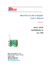
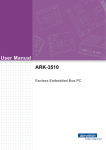
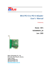
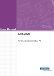
User Manual ARS-2510T3 Railway Embedded Box PC Attention! Please note: This package contains a hard-copy user manual in Chinese for China CCC certification purposes, and there is an English user manual included as a PDF file on the CD. Please disregard the Chinese hard copy user manual if the product is not to be sold and/or installed in China. ii ARS-2510 User Manual Copyright The documentation and the software included with this product are copyrighted 2010 by Advantech Co., Ltd. All rights are reserved. Advantech Co., Ltd. reserves the right to make improvements in the products described in this manual at any time without notice. No part of this manual may be reproduced, copied, translated or transmitted in any form or by any means without the prior written permission of Advantech Co., Ltd. Information provided in this manual is intended to be accurate and reliable. However, Advantech Co., Ltd. assumes no responsibility for its use, nor for any infringements of the rights of third parties, which may result from its use. Acknowledgements Award is a trademark of Award Software International, Inc. VIA is a trademark of VIA Technologies, Inc. IBM, PC/AT, PS/2 and VGA are trademarks of International Business Machines Corporation. Intel® and Pentium® are trademarks of Intel Corporation. Microsoft Windows® is a registered trademark of Microsoft Corp. RTL is a trademark of Realtek Semi-Conductor Co., Ltd. ESS is a trademark of ESS Technology, Inc. UMC is a trademark of United Microelectronics Corporation. SMI is a trademark of Silicon Motion, Inc. Creative is a trademark of Creative Technology LTD. CHRONTEL is a trademark of Chrontel Inc. All other product names or trademarks are properties of their respective owners. For more information about this and other Advantech products, please visit our website at: http://www.advantech.com/ http://www.advantech.com/ePlatform/ For technical support and service, please visit our support website at: http://support.advantech.com.tw/support/ iii Part No. 2006251000 Edition 1 Printed in China September 2013 ARS-2510 User Manual Product Warranty (2 Years) Advantech warrants to you, the original purchaser, that each of its products will be free from defects in materials and workmanship for two years from the date of purchase. This warranty does not apply to any products which have been repaired or altered by persons other than repair personnel authorized by Advantech, or which have been subject to misuse, abuse, accident or improper installation. Advantech assumes no liability under the terms of this warranty as a consequence of such events. Because of Advantech’s high quality-control standards and rigorous testing, most of our customers never need to use our repair service. If an Advantech product is defective, it will be repaired or replaced at no charge during the warranty period. For out-of- warranty repairs, you will be billed according to the cost of replacement materials, service time and freight. Please consult your dealer for more details. 1. Collect all the information about the problem encountered. (For example, CPU speed, Advantech products used other hardware and software used, etc.) Note anything abnormal and list any onscreen messages you get when the problem occurs. 2. Call your dealer and describe the problem. Please have your manual, product, and any helpful information readily available. 3. If your product is diagnosed as defective, obtain an RMA (return merchandise authorization) number from your dealer. This allows us to process your return more quickly. 4. Carefully pack the defective product, a fully-completed Repair and Replacement Order Card and a photocopy proof of purchase date (such as your sales receipt) in a shippable container. A product returned without proof of the purchase date is not eligible for warranty service. 5. Write the RMA number visibly on the outside of the package and ship it prepaid to your dealer. Declaration of Conformity FCC Class A Note: This equipment has been tested and found to comply with the limits for a Class A digital device, pursuant to part 15 of the FCC Rules. These limits are designed to provide reasonable protection against harmful interference when the equipment is operated in a commercial environment. This equipment generates, uses, and can radiate radio frequency energy and, if not installed and used in accordance with the instruction manual, may cause harmful interference to radio communications. Operation of this equipment in a residential area is likely to cause harmful interference in which case the user will be required to correct the interference at his own expense. iv ARS-2510 User Manual Technical Support and Assistance 1. Visit the Advantech web site at www.advantech.com/support where you can find the latest information about the product. 2. Contact your distributor, sales representative, or Advantech's customer service center for technical support if you need additional assistance. Please have the following information ready before you call: – Product name and serial number – Description of your peripheral attachments – Description of your software (operating system, version, application software,etc.) – A complete description of the problem – The exact wording of any error messages Warnings and Cautions Warning! Warnings indicate conditions, which if not observed, can cause personal injury! Caution! Cautions are included to help you avoid damaging hardware or losing data. e.g. There is a danger of a new battery exploding if it is incorrectly installed. Do not attempt to recharge, force open, or heat the battery. Replace the battery only with the same or equivalent type recommended by the manufacturer. Discard used batteries according to the manufacturer's instructions. Avertissements et Precautions Attention! Consignes à respecter afin d’éviter des blessures! Danger! Les précautions à suivre sont indiquées pour éviter la perte des données et éviter d'endommager le matériel. Il y a un danger d'explosion de la batterie si celle-ci est mal installée. Ne pas essayer de recharger, d'ouvrir de force ou de chauffer la batterie. Remplacez la batterie uniquement avec le même type ou équivalent recommandé par le fabricant. Jetez les batteries usagées selon les instructions du fabricant. v ARS-2510 User Manual Safety Instructions 1. Please read these safety instructions carefully. 2. Please keep this User’s Manual for later reference. 3. Please disconnect this equipment from AC outlet before cleaning. Use a damp cloth. Don’t use liquid or sprayed detergent for cleaning. Use moisture sheet or clothe for cleaning. 4. For pluggable equipment, the socket-outlet shall near the equipment and shall be easily accessible. 5. Please keep this equipment from humidity. 6. Lay this equipment on a reliable surface when install. A drop or fall could cause injury. 7. The openings on the enclosure are for air convection hence protecting the equipment from overheating. DO NOT COVER THE OPENINGS. 8. Make sure the voltage of the power source when connecting the equipment to the power outlet. 9. Place the power cord such a way that people cannot step on it. Do not place anything over the power cord. 10. All cautions and warnings on the equipment should be noted. 11. If the equipment is not used for long time, disconnect the equipment from mains to avoid being damaged by transient over-voltage. 12. Never pour any liquid into ventilation openings; this could cause fire or electrical shock. 13. Never open the equipment. For safety reasons, only qualified service personnel should open the equipment. 14. If one of the following situations arises, get the equipment checked by service personnel: The power cord or plug is damaged. Liquid has penetrated into the equipment. The equipment has been exposed to moisture. The equipment does not work well, or you cannot get it to work according to the user's manual. The equipment has been dropped and damaged. The equipment has obvious signs of breakage. 15. Do not leave this equipment in an environment where the storage temperature may go below -40° C (-40° F) or above 85° C (185° F). This could damage the equipment. the equipment should be in a controlled environment. 16. Caution: Danger of explosion if battery is incorrectly replaced. Replace only with the same or equivalent type recommended by the manufacturer, discard used batteries according to the manufacturer's instructions. 17. The sound pressure level at the operator's position according to IEC 704-1:1982 is no more than 70 dB (A). 18. RESTRICTED ACCESS AREA: The equipment should only be installed in a Restricted Access Area. 19. DISCLAIMER: This set of instructions is given according to IEC 704-1. Advantech disclaims all vi ARS-2510 User Manual responsibility for the accuracy of any statements contained herein. vii ARS-2510 User Manual Contents Chapter 1 1.1 1.2 1.3 1.4 1.5 1.6 General Introduction ................................. 1 Introduction ...................................................................................... 2 Product Features.............................................................................. 2 1.2.1 General .................................................................................. 2 1.2.2 Display ................................................................................... 2 1.2.3 Power Consumption .............................................................. 2 Chipset ............................................................................................. 2 1.3.1 Block Diagram ....................................................................... 3 Figure 1.1 ARK-2150 Block diagram……..………….............. 3 Mechanical Specifications................................................................ 3 1.4.1 Dimensions ............................................................................ 3 Figure 1.2 ARK-2150 Mechanical dimension drawing........... 4 1.4.2 Weight.................................................................................... 4 Power Requirement ......................................................................... 4 1.5.1 System Power........................................................................ 4 1.5.2 RTC Battery ........................................................................... 4 Environment Specification................................................................ 4 1.6.1 Operating Temperature.......................................................... 4 1.6.2 Relative Humidity ................................................................... 5 1.6.3 1.6.4 1.6.5 1.6.6 1.6.7 Chapter 2 2.1 2.2 Storage Temperature............................................................. 5 Vibration during Operation ..................................................... 5 Shock during Operation ......................................................... 5 Safety..................................................................................... 5 EMC....................................................................................... 5 H/W Installation ...........................................6 Introduction ....................................................................................... 7 Internal Connectors……………………………………………………… 7 2.2.1 Connector List…………………………………………………… 7 Table 2.1 Connector List of Main Board………………………. 7 2.2.2 Connector Location……………………………………………… 7 Figure 2.1 Internal Connector of MB Top Side..…...…………. 7 Figure 2.2 Internal Connector of MB Bottom Side……....…… 8 2.2.3 Connector Pin Assignment…………………………………….. 8 2.2.3.1 Reset Header (CN2)/Power Switch Header (CN20). 8 viii ARS-2510 User Manual Figure 2.3 Reset Header………….………..………… 8 Table 2.2 Reset Header…………….………..………. 8 2.2.3.2 Power 12V Connector (CN3)……….…………..……. 8 Figure 2.4 Power 12V Connector….……………..….. 9 Table 2.3 Power 12V Connector ………………….… 9 2.2.3.3 GSM-R Voice Header (CN9)……….………………… 9 Figure 2.5 GSM-R Voice Header...………………..… 9 Table 2.4 GSM-R Voice Header …………………..… 9 2.2.3.4 GPS Connector (CN14)…………...……………….… 9 Figure 2.6 GPS Connector………...…………………. 9 Table 2.5 GPS Connector……...……………..…….. 10 2.2.3.5 WLAN Slot (CN29)………………..……..………….. 10 Figure 2.7 WLAN Slot.…..……………….………….. 10 Table 2.6 WLAN Slot………………………………….10 2.2.3.6 WWLAN Slot (CN45)...…….…………………………11 Figure 2.8 WWLAN Slot………………………………11 Table 2.7 WWLAN Slot……………………………… 11 2.2.3.7 WWLAN/GSM-R SIM Slot (CN46/CN47)…………. 12 Figure 2.9 SIM Slot…………...……………………… 12 Table 2.8 WWLAN SIM Slot……...…………………. 12 Table 2.9 GSM-R SIM Slot……………..…………… 12 2.2.3.8 GSM-R Connector (CN48)…….…….……………… 13 Figure 2.10 GSM-R Connector……….…………….. 13 Table 2.10 GSM-R Connector……....……………… 13 2.2.3.9 USB Header (CN59)………………………………… 14 Figure 2.11 USB Header……………………………. 14 Table 2.11 USB Header……...……………………... 14 2.2.3.10 LAN Header (CN60/CN61)…...……….…………..… 14 Figure 2.12 LAN Header……………………..……… 14 Table 2.12 LAN Header…………..…………………. 14 2.2.3.11 Audio Header (CN62)……………….....……………. 14 Figure 2.13 Audio Header…….....………………….. 14 Table 2.13 Audio Header………………………….… 14 2.2.3.12 LED Header (CN63)……………….....……...………. 15 2.3 Figure 2.14 LED Header……………..……………… 15 Table 2.14 LED Header……………...……………… 15 2.2.3.13 USB 3.0 Header (CN67)…………........……………..15 Figure 2.15 USB 3.0 Header ..……………………… 15 Table 2.15 USB 3.0 Header ………..………………..15 External Connectors…………………………………….………..…….. 16 2.3.1 Front External I/O Connectors………………………..………. 16 ix ARS-2510 User Manual Figure 2.16 ARS-2510 IO Connector Drawing ….………….. 16 2.3.1.1 LED Indicators ………………………..……………... 16 Figure 2.17 LED Indicators…………..……………... 17 Table 2.16 LED Indicators………………….………. 17 2.3.1.2 Power ON / OFF Button….………..……………….. 17 Figure 2.18 Power Button…….…………………….. 17 2.3.1.3 VGA Connector………………………………………. 17 Figure 2.19 VGA Connector…….……………………17 Table 2.17 VGA Connector…….…………………… 17 2.3.1.4 DVI-D Connector…………….………………………. 18 Figure 2.20 DVI-D Connector ……………………… 18 Table 2.18 DVI-D connector………………………... 18 2.3.1.5 COM Connector……………………………………… 18 Figure 2.21 COM Connector ...…………………….. 18 Table 2.19 COM Connector………,,,………………. 19 2.3.1.6 USB 3.0 Connector………………………………….. 19 Figure 2.22 USB 3.0 Connector……………………. 19 Table 2.20 USB 3.0 Connector…………………….. 19 2.3.1.7 M12 A-Coded LAN Connector……………………… 19 Figure 2.23 M12 LAN Connector…………………… 20 Table 2.21 LAN Connector with M12 A-coded……. 20 2.3.1.8 M12 A-Coded USB 2.0 Connector…………………. 20 Figure 2.24 M12 USB 2.0 Connector…...…………. 20 2.4 Table 2.22 M12 USB 2.0 Connector…………...….. 20 2.3.1.9 Multi IO Connector….……………………………..… 20 Figure 2.25 Multi IO Connector…………………….. 20 Table 2.23 Multi IO Connector……………………… 20 2.3.2 Rear external I/O Connectors……………………………...…… 21 2.3.2.1 Power Input Connector……………………………… 21 Figure 2.26 M12 Power Input Connector……..…… 21 Table 2.2.4 Power Input Connector……………….. 21 Installation……………………………………………………………….. 21 2.4.1 GSM-R and SIM Card Installation……………………………. 21 2.4.2 Chapter 3 3G / LTE Card and mSATA Installation……......……………. 22 BIOS Settings ............................................. 26 Figure 3.1 Setup program initial screens…………………………………….. 27 3.1 Entering Setup.......................................................................................... 27 3.2 Main Setup……….……………………………………………………………… 27 x ARS-2510 User Manual Figure 3.2 Main Setup Screens………………………..……………………… 28 3.2.1 3.3 System Time / System Date…………….……………..……………… 28 Advanced BIOS Features Setup………………………………………………. 28 Figure 3.3 Advanced BIOS Features Setup Screen…………………...…… 29 3.3.1 Select COM1 / COM2 Type………………………….……..………… .29 Figure 3.4 Select COM1/COM2 type………………………………... 29 3.3.2 ACPI Settings…………………………………………………………... 30 Figure 3.5 ACPI Setting………………………………………………. 30 3.3.3 CPU Configuration……………………………………………………... 30 Figure 3.6 CPU Configuration………………………………………... 30 3.3.4 SATA Configuration..………………………………………………….. 31 Figure 3.7 SATA Configuration…….……...………………………… 31 3.3.5 AMT Configuration……………………………………………………... 32 Figure 3.8 AMT Configuration………………………………………... 32 3.3.6 PCH-FW Configuration……………………………………….……….. 33 Figure 3.9 PCH-FW Configuration………………………….……….. 33 3.3.7 Intel® Anti-Technology Configuration……………………….……….. 33 Figure 3.10 Intel® Anti-Theft Technology Configuration………….. 34 3.3.8 USB Configuration………………………………………….………….. 34 Figure 3.11 USB Configuration………………………..….…………… 34 3.3.9 SMART Settings…………………………….…………………………. 35 Figure 3.12 Smart Setting…………………………………..………..... 35 3.3.10 Embedded Controller Configuration………………………………….. 35 Figure 3.13 Embedded Controller Configuration………..………….. 36 3.3.11 Platform Misc Configuration……………………....…………………… 36 Figure 3.14 Platform Misc Configuration……….………………..…… 37 3.3.12 Intel (R) Smart Connect Technology…………...…………………….. 37 Figure 3.15 Intel ® Smart Connect Technology………....………….. 37 3.3.13 CPU PPM Configuration……………………...……………………….. 38 Figure 3.16 CPU PPM Configuration……..………………………….. 38 3.4 Chipset.………………………………………………………….……………….. 38 Figure 3.17 Chipset Setup…..…………………………………………………. 39 3.4.1 PCH-IO Configuration…………………………………………………. 39 Figure 3.18 PCH-IO Configuration……………………...…………….. 39 3.4.2 System Agent (SA) Configuration……………………………………. 40 Figure 3,19 System Agent(SA) Configuration…..………….………... 40 3.5 Boot Settings..…………………………………………………………………… 41 Figure 3.20 Boot Setup Utility………………..……………………………….. 41 3.6 Security Setup..…………………………………………………………………. 42 Figure 3.21 Password Configuration…………………………..…………….. 42 3.7 Save & Exit…………..………………………………………………………….. 43 xi ARS-2510 User Manual Figure 3.22 Save & Exit…………………………...…………………………… 43 Appendix A Watchdog Timer Sample Code.............. 45 A.1 EC Watchdog Timer Sample Code............................................................. 46 xii ARS-2510 User Manual Chapter 1 1 General Information This chapter gives background information on the ARS-2510 Computing Box. Sections include: Introduction General Specifications Dimensions 1.1 Introduction The ARS-2510 is a dedicated box computer for railway. ARS-2510 combines various I/O connectors which can be connected to devices such as LED displays (PIDS System). Dual display / dual audio interfaces supporting different resolutions are able to deliver various applications to diverse displays. Built-in multiple communication modules (WWAN, GPS, GSM-R) make ARS-2510 send train position information back to the control center. ARS-2510 is able to work well under extreme conditions such as wide operating temperature range (-25 ° C to 70 °C). 1.2 Production Features 1.2.1 General Intel® Core™ i7-3517UE Processor 1.7GHz Dual display and support wide screen with high resolution Support 2 x GbE , 2 x USB 3.0, 1 x USB 2.0 and 2 x COM ports Support 2 x expansion SSD modules for RAID function Train grade working temperature range (-25° C to 70° C) 1.2.2 Display Controller: Intel HD Graphics 4000 Resolution: 1.2.3 - VGA: Support up to 2048x1536 with 32-bit color at 75Hz - DVI-D: Support DVI-D up to 1920 x 1200 Power Consumption Typical: 23 W (CPU is Intel® Core™ i7-3517UE 1.7GHz and w/o expansion) Max: 40 W (CPU is intel® Core™ i7-3517UE 1.7GHz and w/o expansion) 1.3 Hardware Specifications CPU: Intel® Core™ i7-3517UE Processor 1.7GHz System Chipset: Intel® QM77 I/O Controller System Memory: DDR 1600MHz up to 8GB I/O Interface: - 2 x Serial ports (RS-232/422/485) 2 x Giga LAN ports (M12 A-coded) 2 ARS-2510 User Manual USB: - 2 x USB 3.0 and 1 x USB 2.0(M12 A-coded) Audio: High Definition Audio (HD), SPK, Line out, Mic-in Storage: 1 x mSATA and 1 x Cfast Expansion Interface: Support WWAN with SIM holder, GSM-R with SIM holder and WLAN Software API: Advantech iManager and SUSIAccess 1.3.1 Chapter 1 Block Diagram General Information Figure 1.1 ARS-2510 Block Diagram 1.4 Mechanical Specifications 1.4.1 Dimensions 270[10.62] x 126.5[4.98] x 90[3.54] (Unit: mm [Inch]) 3 ARS-2510 User Manual Figure 1.2 ARS-2510 Mechanical dimension drawing 1.4.2 Weight 5 kg (11lb) 1.5 Power Requirement 1.5.1 System Power Power Input: 24Vdc@ 4.16A 48Vdc@ 1.56A 72Vdc@ 2.1A 110Vdc@ 0.9A 1.5.2 RTC Battery Lithium 3V / 210 mAh 1.6 Environment Specification 1.6.1 Operating Temperature With Industrial Grade SSD / Cfast: -25 ~ 70 ℃ (-13 ~140 ℉), with air flow. Speed=0.7 m/sec Certified Safety Temperature: 50℃ (122℉) 4 ARS-2510 User Manual 1.6.2 Relative Humidity 1.6.3 When system is equipped with SSD / mSATA: 5Grms, IEC 60068-2-27, half sine 11 ms duration. Safety UL, CCC, EN50155 compliant 1.6.7 EMC CE / FCC Class A, CCC, EN50155 compliant 5 ARS-2510 User Manual General Information When system is equipped with SSD / mSATA: 5Grms, IEC 60068-2-64, random, 5 – 500 Hz 1hr/axis, x,y,z 3 axes. Shock during Operation 1.6.6 -40 ~ 85℃ (-40 ~ 185℉) Vibration during Operation 1.6.5 95%@ 40℃ (non-condensing) Storage Temperature 1.6.4 Chapter 1 Chapter 2 2 H/W Installation This chapter introduces external IO and the installation of ARS2510 hardware. 2.1 Introduction The following sections show the internal connectors and the external connectors pin assignment for application. 2.2 Internal Connectors Table 2.1: Connector List of Main Board CN2 Reset Header CN46 WWLAN SIM Slot CN3 Power 12V Connector CN47 GSM-R SIM Slot CN9 GSM-R Voice Header CN48 GSM-R Connector CN12 Memory Socket CN59 USB Header CN14 GPS Connector CN60 LAN1 Header CN20 Power Switch Header CN61 LAN2 Header CN28 mSATA Slot CN62 Audio Header CN29 WLAN Slot CN63 LED Header CN30 CFast Slot CN67 USB 3.0 Header CN45 WWLAN Slot BH1 Battery Header 2.2.1 Connector List 2.2.2 Connector Location Figure 2.1 Internal Connectors of MB Top Side 7 ARS-2510 User Manual Chapter 2 Hardware Installation Figure 2.2 Internal Connectors of MB Bottom Side 2.2.3 Connector Pin Assignment 2.2.3.1 Reset header (CN2) / Power Switch Header (CN20) Figure 2.3 Reset Header Table 2.2 Rest header (CN2) Pin Signal 1 Reset /Power Switch 2 GND 2.2.3.2 Power 12V Connector (CN3) 8 ARS-2510 User Manual Figure 2.4 Power 12V Connector Table 2.3 Power 12V Connector (CN3) Pin Signal Pin Signal 1 GND 2 GND 3 +12V 4 +12V 2.2.3.3 GSM-R Voice Header (CN9) Figure 2.5 GSM-R Voice Header Table 2.4 GSM-R Voice Header (CN9) Pin Signal Pin Signal 1 LOUT_L 2 LOUT_R 3 GND 4 GND 5 MIC_L 6 MIC_R 7 GND 8 GND 2.2.3.4 GPS Connector (CN14) Figure 2.6 GPS connector 9 ARS-2510 User Manual Signal Pin Signal 1 VCC(5V) 2 VCC(5V) 3 USB - 4 GND 5 USB + 6 SPEED+ 7 GND 8 GND_ISO 9 GPS 10 FWS+ 11 GPS 12 GND_ISO 13 LED_GPS# 14 NC 15 V_BAT(3.3V) 16 NC 17 EN_USB 18 NC 19 GND 20 GND 2.2.3.5 WLAN Slot (CN29) Figure 2.7 WLAN Slot Table 2.6 WLAN Slot (CN29) Pin Signal Pin Signal 1 PCIE_WAKE 2 +3.3V 3 NC 4 GND 5 NC 6 NC 7 CLKREQ4 8 NC 9 GND 10 NC 11 CLK_PCIE- 12 NC 13 CLK-PCIE+ 14 NC 15 GND 16 NC 17 NC 18 GND 19 NC 20 +3.3V_SB 21 GND 22 RLTRST# 23 PCIE_RX- 24 NC 25 PCIE_RX+ 26 GND 10 ARS-2510 User Manual Hardware Installation Pin Chapter 2 Table 2.5 GPS Connector (CN14) 27 GND 28 +1.5V 29 GND 30 NC 31 PCEI_TX- 32 NC 33 PCEI_TX+ 34 GND 35 GND 36 USB- 37 GND 38 USB+ 39 NC 40 NC 41 NC 42 NC 43 GND 44 LED_WLAN 45 NC 46 NC 47 NC 48 +1.5V 49 NC 50 GND 51 NC 52 VCC3(3.3V) 2.2.3.6 WWLAN Slot (CN45) Figure 2.8 WWLAN Slot Table 2.7 WWLAN slot (3G/LTE) Pin Signal Pin Signal 1 NC 2 +3.3V 3 UART_RI# 4 GND 5 NC 6 NC 7 GND 8 +VUIM_PWR 9 NC 10 UIM_DATA 11 NC 12 UIM_CLK 13 NC 14 UIM_RESET 15 GND 16 NC 17 +1.8V 18 GND 19 UART_CTS# 20 NC 11 ARS-2510 User Manual 22 PLTRST# 23 UART_RXD 24 +3.3V 25 UART_RTS 26 GND 27 GND 28 NC 29 GND 30 NC 31 UART_TXD 32 NC 33 UART_DCD# 34 GND 35 GND 36 USB- 37 GND 38 USB+ 39 +3.3V 40 GND 41 +3.3V 42 LED_WAN 43 NC 44 UART_DTR# 45 NC 46 UART_DSR# 47 NC 48 NC 49 NC 50 GND 51 NC 52 VCC3(3.3V) 2.2.3.7 WWLAN/GSM-R SIM Slot (CN46/CN47) Figure 2.9 SIM slot Table 2.8 WWLAN SIM Slot (CN46) Pin Signal Pin Signal C1 +VUM_PWR C2 UIM_RESET C3 UIM_CLK C5 GND C6 NC C7 UIM_DATA Table 2.9 GSM-R SIM Slot (CN47) Pin Signal Pin Signal C1 VSIM C2 SIM_REST C3 SIM_CLK C5 GND_USIM C6 NC C7 SIM_DATA 12 ARS-2510 User Manual Hardware Installation GND Chapter 2 21 2.2.3.8 GSM-R Connector (CN48) Figure 2.10 GSM-R Connector Table 2.10 GSM-R Connector Pin Signal Pin Signal 1 USIM_CLK 2 +VUSIM 3 USIM_DATA 4 USIM_RST 5 USIM_PRSNT 6 GND_USIM 7 NC 8 NC 9 NC 10 NC 11 NC- 12 NC 13 FLASH 14 RXD2_RF 15 RXD1_RF 16 TXD2_RF 17 TXD1_RF 18 NC 19 NC 20 NC 21 GND 22 GND 23 GND 24 GND 25 GND 26 +V3.3_WWAN 27 +V3.3_WWAN 28 +V3.3_WWAN 29 +V3.3_WWAN 30 +V3.3_WWAN 31 +VINT_GPRS 32 RI1#_RF 33 DSR1#_RF 34 RTS1#_RF 35 DTR1#_RF 36 RTS2#_RF 37 CTS1#_RF 38 CTS2#_RF 39 DCD1#_RF 40 EMERGOFF 41 IGT# 42 GND 43 MICN_GSMR 44 MICP_GSMR 45 NC 46 NC 47 NC 48 NC 49 SPK2P 50 SPK2N 13 ARS-2510 User Manual USB Header (CN59) Chapter 2 2.2.3.9 Figure 2.11 USB Header Pin Signal Pin Signal 1 +V5_USB 2 USB- 3 USB+ 4 GND 2.2.3.10 LAN Header (CN60/CN61) Figure 2.12 LAN Header Table 2.12 LAN Header (CN60/CN61) Pin Signal Pin Signal 1 LAN_DMI3- 2 LAN_DMI3+ 3 LAN_DMI2- 4 LAN_DMI2+ 5 LAN_DMI1- 6 LAN_DMI1+ 7 LAN_DMI0- 8 LAN_DMI0+ 2.2.3.11 Audio Header (CN62) Figure 2.13 Audio Header Table 2.13 Audio Header (CN62) Pin Signal Pin 14 Signal ARS-2510 User Manual Hardware Installation Table 2.11 USB Header 1 LIN_L 2 LIN_R 3 GND_AUD 4 GND_AUD 5 APORT_L1 6 GND_CAR_BAT 7 APORT_R1 8 IGNTION 9 GND 10 FWD+ 11 MIC1L 12 SPEED+ 13 MIC1R 14 GND_ISO 2.2.3.12 LED Header (CN63) Figure 2.14 LED Header Table 2.14 LED Header (CN63) Pin Signal Pin Signal 1 NC 2 NC 3 LAN2_LINK100# 4 LAN2_LINK1000# 5 +3.3VSB 6 LAN2_ACT# 7 LAN1_LINK100# 8 LAN1_LINK1000# 9 +3.3VSB 10 LAN1_ACT# 11 +5V 12 GND 13 +3.3V 14 HDD_LED# 2.2.3.13 USB 3.0 Header (CN67) Figure 2.15 USB 3.0 Header Table 2.15 USB 3.0 Header (CN67) Pin Signal Pin Signal 1 +V5_USB 2 USB1_SSRX- 3 USB1_SSRX+ 4 GND 15 ARS-2510 User Manual USB1_SSTX- 6 USB1_SSTX+ 7 GND 8 USB0_P- 9 USB_P+ 10 NC 11 USB1_P+ 12 USB1_P- 13 GND 14 USB2_SSTX+ 15 USB2_SSTX- 16 GND 17 USB2_SSRX+ 18 USB2_SSRX- 19 +V5_USB Hardware Installation 2.3 External Connectors 2.3.1 Front External I/O Connectors Figure 2.16 ARS-2510 IO Connector Drawing 2.3.1.1 LED Indicators There are six LEDs on ARS-2510 front metal surface plate for system status indication: PWR LED stands for power status, HDD LED stands for HDD status, and LAN LED stands for LAN speed and active status. 16 Chapter 2 5 ARS-2510 User Manual Chapter 2 . Figure 2.17 LED Indicators 2.3.1.2 10/100 Orange 1000 Green Power ON/OFF Button ARS-2510 comes with a Power ON/OFF button which supports dual functions of Soft Power -ON/OFF (Instant off or 4 Seconds Delay). Figure 2.18 Power Button 2.3.1.3 VGA Connector The ARS-2510 provides a high resolution VGA interface connected by a D-sub 15-pin connector in order to support an external VGA CRT monitor. It supports resolution up to 1900 x 1200. Figure 2.19 VGA Connector Table 2.17 VGA Connector Pin Signal Pin Signal 1 Red 2 Green 3 Blue 4 NC 5 GND 6 GND 7 GND 8 GND 9 NC 10 GND 17 ARS-2510 User Manual Hardware Installation Table 2.16 LAN LED Indicator 11 NC 12 NC 13 H-SYNC 14 V-SYNC 15 NC 2.3.1.4 DVI-D Connector ARS-2510 offers a Digital Visual Interface connector by a D-sub 24-pin female DVI-D connector which is only for digital video signal. The interface supports high-speed and high-resolution digital displays. Figure 2.20 DVI Connector Table 2.18 DVI-D Connector Pin Signal Pin Signal 1 TMDS Data 2- 2 TMDS data 2+ 3 GND 4 NC 5 NC 6 DDC clock 7 DDC data 8 NC 9 TMDS Data 1- 10 TMDS Data 1+ 11 GND 12 NC 13 NC 14 +5V 15 GND 16 Hot plug detect 17 TMDS Data 0- 18 TMDS Data 0+ 19 GND 20 NC 21 NC 22 GND 23 TMDS clock+ 24 TMDS clock- 2.3.1.5 COM Connector ARS-2510 provides two D-sub 9-pin connectors which offer RS-232/422/485 serial communication interface. The default setting is RS-232 and RS-422/485 can be selected in BIOS. The BIOS setting of RS-232/422/485 can be found in Chapter 3. Figure 2.21 COM connector 18 ARS-2510 User Manual RS-232 RS-422 RS-485 1 DCD# TX- Data - 2 RXD TX+ Data + 3 TXD RX+ NC 4 DTR# RX- NC 5 GND GND GND 6 DSR# NC NC 7 RTS# NC NC 8 CTS# NC NC 9 RI# NC NC 2.3.1.6 USB 3.0 Connector ARS-2510 supports USB3.0 interface which gives a complete Plug & Play and hot swapping with up to 127 external devices. Figure 2.22 USB 3.0 Connector Table 2.20 USB 3.0 Connector Pin Signal Pin Signal 1 +5V 2 USB_data- 3 USB_data+ 4 GND 5 SSRX- 6 SSRX+ 7 GND 8 SSTX- 9 SSTX+ 2.3.1.7 M12 A-Coded LAN Connector Figure 2.23 M12 LAN Connector 19 ARS-2510 User Manual Hardware Installation Pin Chapter 2 Table 2.19 COM connector Table 2.21 LAN Connector of M12 A-Coded Pin Signal Pin Signal 1 MDI2+ 2 MDI3+ 3 MDI3- 4 MDI0- 5 MDI1+ 6 MDI0+ 7 MDI2- 8 MDI1- 2.3.1.8 M12 A-Coded USB 2.0 Connector Figure 2.24 M12 USB Connector Table 2.22 USB Connector of M12 A-Coded Pin Signal Pin Signal 1 Data - 2 +5V 3 Data + 4 GND 2.3.1.9 Multi IO Connectors Figure 2.25 Multi IO Connector Table 2.23 Multi IO Connector Pin Signal Pin Signal 1 Line L 2 GND_AUD 3 IGNITION 4 NC 5 FWD+ 6 Line R 7 APORT_L1 8 GND_CAR_BAT 9 GND_AUD 10 GND-ISO 11 GND_AUD 12 APORT_R1 13 MIC_L 14 MIC_R 15 SPEED+ 2.3.2 Rear external I/O Connectors 20 ARS-2510 User Manual 2.3.2.1 Power Input Connector ARS-2510 comes with a 4-pins M12 A-coded connector which is for VDC external power input. Figure 2.26 M12 Power input connector Table 2.24 Power Input Connector Pin Signal Pin Signal 1 GND 2 VDC 3 VDC 4 GND Please make the earth lead well locked at the ground screw. 2.4 Installation 2.4.1 GSM-R and SIM Card Installation 1. Unscrew the four screws at the top cover. 2. Unscrew the four screws at the right and left side of top cover. 21 ARS-2510 User Manual Chapter 2 Hardware Installation 2.4.2 3. Remove the top cover. 4. Install the GSM-R module into CN48 and SIM card into CN47. 5. Recover the top cover and screws. 3G/LTE SIM Card and mSATA Installation 1. Unscrew the four screws at the front side. 22 ARS-2510 User Manual 2. Remove the expansion trays from the front side. 3. Unscrew the four screws at the bottom side. 4. Unscrew five screws at the rear side. 23 ARS-2510 User Manual Chapter 2 6. Hardware Installation 5. Remove the bottom cover. Install mSATA module into CN28 and 3G/LTE SIM card into CN46. 24 ARS-2510 User Manual 7. 8. Install Cfast card into CN30. Recover the bottom cover and screws. 25 ARS-2510 User Manual Chapter 3 BIOS Settings 3 AMIBIOS has been integrated into many motherboards for over a decade. With the AMIBIOS Setup program, users can modify BIOS settings and control various system features. This chapter describes the basic navigation of the ARS-2510 BIOS setup screens. Figure 3.1 Setup Program Initial Screens AMI's BIOS ROM has a built-in Setup program that allows users to modify the basic system configuration. This information is stored in flash ROM so it retains the Setup information when the power is turned off. 3.1 Entering Setup Turn on the computer and then press <F2> or <DEL> to enter Setup menu. 3.2 Main Setup When users first enter the BIOS Setup Utility, users will enter the Main setup screen. Users can always return to the Main setup screen by selecting the Main tab. There are two Main Setup options. They are described in this section. The Main BIOS Setup screen is shown below. 27 ARS-2510 User Manual Chapter 3 BIOS Operation Figure 3.2 Main Setup Screens The Main BIOS setup screen has two main frames. The left frame displays all the options that can be configured. Grayed-out options cannot be configured; options in blue can. The right frame displays the key legend. Above the key legend is an area reserved for a text message. When an option is selected in the left frame, it is highlighted in white. Often a text message will accompany it. 3.2.1 System Time / System Date Use this option to change the system time and date. Highlight System Time or System Date using the <Arrow> keys. Enter new values through the keyboard. Press the <Tab> key or the <Arrow> keys to move between fields. The date must be entered in MM/DD/YY format. The time must be entered in HH:MM:SS format. 3.3 Advanced BIOS Features Setup Select the Advanced tab from the ARS-2510 setup screen to enter the Advanced BIOS Setup screen. Users can select any item in the left frame of the screen, such as CPU Configuration, to go to the sub menu for that item. Users can display an Advanced BIOS Setup option by highlighting it using the <Arrow> keys. All Advanced BIOS Setup options are described in this section. The Advanced BIOS Setup screens are shown below. The sub menus are described on the following pages. 28 ARS-2510 User Manual Figure 3.3 Advanced BIOS Features Setup Screen 3.3.1 Select COM1/COM2 Type This item allows users to select RS-232/RS-422/RS-485 for COM1&COM2. Figure 3.4 Select COM1/COM2 Type 29 ARS-2510 User Manual 3.3.2 ACPI Settings Chapter 3 BIOS Operation Figure 3.5 ACPI Setting Enable ACPI Auto Configuration This item allows users to enable or disable BIOS ACPI auto configuration. Resume On RTC Alarm This item allows users to enable or disable System wake on alarm event. When enabled, hr:: min::sec specified 3.3.3 CPU Configuration 30 ARS-2510 User Manual Figure 3.6 CPU Configuration Hyper Threading Technology This item allows users to enable or disable Intel® Hyper Threading technology. Active Processor Cores This item allows users to set how many processor cores should be active. Limit CPUID Maximum This item allows users to limit the maximum value of CPUID. Execute Disable Bit This item allows users to enable or disable the No-Execution page protection technology. Intel Virtualization Technology This item allows users to enable or disable the intel virtualization technology. Hardware Prefetcher This item allows users to enable or disable the hardware prefetcher feature. Adjacent Cache Line Prefetch This item allows users to enable or disable the adjacent cache line prefetch feature. 3.3.4 SATA Configuration Figure 3.7 SATA Configuration SATA Controller(s) This item allows users to enable or disable the SATA controller(s). SATA Mode Selection This item allows users to select mode of SATA controller(s). 31 ARS-2510 User Manual 3.3.5 AMT Configuration Chapter 3 BIOS Operation Figure 3.8 AMT Configuration Intel AMT This item allows users to enable or disable Intel AMT BIOS extension. BIOS Hotkey Pressed This item allows users to enable or disable BIOS hotkey press. MEBx Selection Screen This item allows users to enable or disable MEBx selection screen. Hide Un-Configuration ME Confirmation This item allows users to hide un-configure ME without password confirmation prompt. MEBx Debug Message Output This item allows users to enable or disable MEBx debug message. Un-Configure ME This item allows users to un-configure ME without password. Amt Wait Timer Set timer to wait before sending ASF_GET_BOOT_OPTIONS. Disable ME This item allows users to enable or disable Intel ME. ASF This item allows users to enable or disable Alert Specification Format. Activate Remote Assistance Process This item allows users to enable or disable trigger CIRA boot. USB Configure This item allows users to enable or disable USB configure function. PET Progress 32 ARS-2510 User Manual This item allows users to enable or disable PET events progress to recieve PET events or not. AMT CIRA Timeout OEM defined timeout for MPS connection to be established. WatchDog This item allows users to enable or disable WatchDog Timer. OS Timer Set OS watchdog timer. BIOS Timer Set BIOS watchdog timer. 3.3.6 PCH-FW Configuration Figure 3.9 PCH-FW Configuration MDES BIOS Status Code This item allows users to enable or disable MDES BIOS Status Code function. Firmware Update Configuration This item allows users to enable or disable ME FW image re-flash function. 3.3.7 Intel® Anti-Theft Technology Configuration 33 ARS-2510 User Manual Chapter 3 Intel ® Anti-Theft Technology This item allows users to enable or disable Intel ® AT in BIOS for testing only. Intel ® Anti-Theft Technology Rec This item allows users to set the number of times Recovery at temped will be allowed 3.3.8 USB Configuration Figure 3.11 USB Configuration Legacy USB Support 34 ARS-2510 User Manual BIOS Operation Figure 3.10 Intel® Anti-Theft Technology Configuration Enable the support for legacy USB. Auto option disables legacy support if no USB devices are connected. XHCI Hand-Off This is a workaround for the OS without XHCI hand-off support. The XHCI ownership change should claim by XHCI driver. EHCI Hand-Off This is a workaround for the OS without EHCI hand-off support. The EHCI ownership change should claim by EHCI driver USB Transfer Time-Out Set the time-out value for Control, Bulk, and Interrupt transfers. Device Reset Time-Out Set USB mass storage device Start Unit command time-out value. Device Power-Up Delay Set the maximum time of the device will take before it properly reports itself to the Host Controller. 'Auto' uses default value: for a Root port it is 100 ms, for a Hub port the delay is taken from Hub descriptor. 3.3.9 SMART Settings Figure 3.12 Smart Setting SMART Self Test This item allows users to enable or disable SMART Self Test. 3.3.10 Embedded Controller Configuration 35 ARS-2510 User Manual Chapter 3 BIOS Operation Figure 3.13 Embedded Controller Configuration EC iManager WatchDog IRQ This item allows users to select Irq number eBrain Watchdog. EC Power Saving Mode This item allows users to select EC Power Saving Mode. EC iManager Smart FAN This item allows users to Control iManager Smart FAN function Backlight Mode This item allows users to switch backlight mode to PWM or DC mode EC Watch Dog Function This item allows users to select watch dog timer you needs. 3.3.11 Platform Misc Configuration 36 ARS-2510 User Manual Figure 3.14 Platform Misc Configuration Native PCIE Enable This item allows users to enable or disable native PCIE support feature. 3.3.12 Intel (R) Smart Connect Technology Figure 3.15 Intel® Smart Connect Technology ISCT Configuration. This item allows users to enable or disable ISCT Configuration 37 ARS-2510 User Manual 3.3.13 CPU PPM Configuration Chapter 3 BIOS Operation Figure 3.16 CPU PPM Configuration EIST CPU runs at its default speed if disabled; CPU speed is controlled by the operating system if enabled. Turbo Mode This item allows users to enable or disable turbo mode. CPU C3/C6/C7 Report This item allows users to enable or disable CPU C-state support. Configurable TDP This item allows users to select TDP levels. Config TDP LOCK This item allows users to enable or disable Config TDP LOCK. ACPI T State This item allows users to enable or disable ACPI T State. 3.4 Chipset Select the Chipset tab from the ARS-2510 setup screen to enter the Chipset BIOS Setup screen. You can display a Chipset BIOS Setup option by highlighting it using the <Arrow> keys. All Plug and Play BIOS Setup options are described in this section. The Plug and Play BIOS Setup screen is shown below. 38 ARS-2510 User Manual Figure 3.17 Chipset Setup 3.4.1 PCH-IO Configuration Figure 3.18 PCH-IO Configuration PCI Express Configuration This item allows users to configuration PCIE1~PCIE8 root port detail settings. USB Configuration This item allows users to configuration detail of USB functions. 39 ARS-2510 User Manual PCH Azalia Configuration This item allows users to configuration detail of azalia functions. Enables or disables the PCH LAN controller. WiFi Card1 This item allows users to enables or disables the WiFi Card1 if device exist. High Precision Timer Enables or disables the high precision timer. Chapter 3 PCH LAN controller SLP_S4 Assertion Width This item allows users to set a delay of sorts. BIOS Operation Restore AC Power Loss This item allows users to select off, on and last state. 3.4.2 System Agent (SA) Configuration Figure 3.19 System Agent (SA) Configuration VT-d This item allows users to select Enable VT-d function on MCH. DDR Selection This item allows users to select Auto, DDR3 or DDR3L. 40 ARS-2510 User Manual 3.5 Boot Settings Figure 3.20 Boot Setup Utility Setup Prompt Timeout This item allows users to select the number of seconds to wait for setup activation key. Bootup NumLock State Select the Power-on state for Numlock. Quiet Boot If this option is set to Disabled, the BIOS displays normal POST messages. If Enabled, an OEM Logo is shown instead of POST messages. Option ROM Message Set display mode for option ROM. INT19 Trap Response This item allows option ROMs to trap interrupt 19. 41 ARS-2510 User Manual 3.6 Security Setup Chapter 3 BIOS Operation Figure 3.21 Password Configuration Select Security Setup from the ARS-2510 Setup main BIOS setup menu. All Security Setup options, such as password protection is described in this section. To access the sub menu for the following items, select the item and press <Enter>: Change Administrator / User Password: Select this option and press <ENTER> to access the sub menu, and then type in the password. 42 ARS-2510 User Manual 3.7 Save & Exit Figure 3.22 Save & Exit Save Changes and Exit When users have completed system configuration, select this option to save changes, exit BIOS setup menu and reboot the computer if necessary to take effect all system configuration parameters. Discard Changes and Exit Select this option to quit Setup without making any permanent changes to the system configuration. Save Changes and Reset When users have completed system configuration, select this option to save changes, exit BIOS setup menu and reboot the computer to take effect all system configuration parameters. Discard Changes and Reset Select this option to quit Setup without making any permanent changes to the system configuration and reboot the computer. Save Changes When users have completed system configuration, select this option to save changes without exit BIOS setup menu. Discard Changes Select this option to discard any current changes and load previous system configuration. Restore Defaults The ARS-2510 automatically configures all setup items to optimal settings when users select 43 ARS-2510 User Manual this option. Optimal Defaults are designed for maximum system performance, but may not work best for all computer applications. In particular, do not use the Optimal Defaults if the Save User Defaults When users have completed system configuration, select this option to save changes as user defaults without exit BIOS setup menu. Restore User Defaults The users can select this option to restore user defaults. Chapter 3 user’s computer is experiencing system configuration problems. BIOS Operation 44 ARS-2510 User Manual Appendix A Watchdog Timer Sample Code A EC_Command_Port = 0x29Ah EC_Data_Port = 0x299h Write EC HW ram = 0x89 Watch dog event flag = 0x57 Watchdog reset delay time = 0x5E Reset event = 0x04 Start WDT function = 0x28 ==================================================== .model small .486p .stack 256 .data .code org 100h .STARTup mov dx, EC_Command_Port mov al,89h ; Write EC HW ram. out dx,al mov dx, EC_Command_Port mov al, 5Fh ; Watchdog reset delay time low byte (5Eh is high byte) index. out dx,al mov dx, EC_Data_Port mov al, 30h ;Set 3 seconds delay time. out dx,al mov dx, EC_Command_Port mov al,89h ; Write EC HW ram. out dx,al mov dx, EC_Command_Port mov al, 57h ; Watch dog event flag. out dx,al mov dx, EC_Data_Port mov al, 04h ; Reset event. out dx,al mov dx, EC_Command_Port mov al,28h ; start WDT function. out dx,al .exit END 46 ARS-2510 User Manual Appendix A Watchdog Timer Sample Code A.1 EC Watchdog Timer Sample Code