1
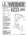
Model No. 831.488540
User's Manual
Setup
1. Firmly press the thumb
tab and pivot the
upright up until it locks in a nearly vertical position.
2.
Insert the handles into the stem until the
lock pins are visible in the holes in the
stern.
3.
Hand
Open the quick-release lever. Depress the
lock pin on the stem and slide the stem
up until the lock pin is visible in one of
the three holes in the upright. When the
stem is at the desired height, close the
quick-release lever so that it is snug
against the upright. If the quick-release is
not snug, see ADJUSTING THE
QUICK-_SE
on the back of this
user's manual.
Before using the scooter, make sure that
the scooter is set up as described and that
all parts are securely tightened.
The decal shown at the right has been placed on the scooter. If the decal is missing, or if it is not legible, please call our
Customer Service Department toll-free at
1-800-999-3756, Monday through Friday,
6 a.m. until 6 p.m. Mountain Time, to
order a free replacement
decal. Apply the
replacement
decal to the location shown.
To prevent
serious Injury:
•Read, understand
and follow all warnlngs and Instructions on the unit
and in the manual,
•Always wear protecllve equipment
Including helmet,
kneapads, wrlst
guards, and elbow
pads.
•Keep away from
cars, streets or
areas that enter
vehicle traffic
mutes.
•Never ride when
towed behind bicycles, motorcycles, or vehicles
Right Side
•Do not ride at
night or In poor
visibility
Storage
1. Open
thequick-release
lever. Depress the
lock pin on the stem and slide the stem
down into the upright. Close the quickrelease lever.
2
3
Depress the lock pins and remove the
handles from the stem. Press the handles
into the storage clip on the upright.
Pull the thumb tab and pivot the upright
down until it locks in the horizontal position.
Hand Brake, Carry Strap, and Cable not shown.
Part List/Exploded
No. Qty.
Drawing Model No. 831.4ui:i )4u
R0700A
Description
1
2
3
1
1
1
Deck
Head Tube
Fork
4
5
6
7
1
1
2
2
Upright
Stem
Handle
Foam Pad
8
9
10
2
3
1
Handle Cap
Lock Pin
Handle Cord
11
12
13
14
15
16
17
18
19
20
21
1
1
1
1
2
2
2
1
1
2
2
Quick Release
Upright Clamp w/Ring
Bearing Nut
Bearing Cap
Bearing
Bearing Race
Bushing
Pivot Union Bolt Set
Front Union Bolt Set
Rear Union Bolt Set
Wheel
22
23
24
2
1
1
Rear Wheel Spacer
Brake Spring
Brake
25
26
27
28
29
30
31
32
33
34
1
1
2
1
1
1
1
4
1
2
Head Tube Spring
Storage Clip
Front Wheel Spacer
Lock Pin
Deck Mount
Deck Cushion
Frame
Deck Screw
Cable Clip
Tek Screw
35
36
37
38
39
40
2
1
1
1
1
1
Brake Spacer
Mount Union Bolt Set
Hand Brake
Brake Bracket
Cable Bracket
Brake Cable
41
42
*
*
2
1
1
1
Flange Nut
Strap Clamp w/Ring
Carry Strap
User's Manual
*The user's manual and carry strap are not shown
Note: Specifications are subject to change without notice.
28
19
27
Ordering Replacement Parts
To order replacement parts, call toll-free 1-800-999-3756,
Monday through Friday, 6 a.m. until 6 p.m. Mountain Time
(excluding holidays). When ordering parts, please mention
the model number (831.488540) and the number and
description of the parts needed.
If the quick-release doesn't hold the stem snug in place,
you will need to adjust it.
Open the quick-release lever. Turn the adjustment nut
clockwise one half turn while keeping the lever from turning. Close the lever. Repeat this procedure until the stem is
held snug in place.
If the quick-release is too snug to close, you will need to
adjust it.
Quick
Release
Close
Open
Adjustment
Nut
While the quick-release lever is open, turn the adjustment
nut counterclockwise one quarter tern while keeping the
lever from turning. Close the lever. Repeat this procedure
until the stem is held snug in place and the quick-release is
closed.
Part No. 167662 R0700A
Printed in China © 2000 ICON Health & Fitness, Inc.