1
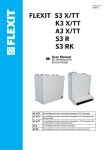
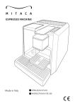
Operating Instructions Single Loop Controller EC48 & EC96 Rev. 1.00.00 03/2010 PSG Plastic Service GmbH Operating Instructions EC48 & EC96 Table of Contents 1 1.1 Introduction........................................................................................................................................... 3 Typographical Conventions................................................................................................................... 4 2 2.1 2.2 General Information............................................................................................................................. 5 Warranty Conditions............................................................................................................................... 5 Installation and safety references.......................................................................................................... 5 3 3.1 3.2 Equipment Implementation ................................................................................................................ 6 Type designation.................................................................................................................................... 6 Scope of Delivery ................................................................................................................................... 6 4 4.1 4.2 Device construction............................................................................................................................. 7 Dimensions............................................................................................................................................. 7 Connection overview.............................................................................................................................. 7 5 Installation/Dismantling ...................................................................................................................... 8 6 6.1 6.2 6.2.1 6.2.2 6.2.3 6.2.4 6.2.5 Electrical connection and operational startup................................................................................ 9 Connection type ..................................................................................................................................... 9 Connector assignment and basic configuration ................................................................................... 9 Power Supply ......................................................................................................................................... 9 Measurement inputs ............................................................................................................................ 10 Control outputs ..................................................................................................................................... 11 Digital outputs....................................................................................................................................... 11 Connection of Current Transformer .................................................................................................... 11 7 Status displays/Diagnostics............................................................................................................. 12 8 8.1 8.1.1 8.1.2 8.1.3 8.1.4 8.2 8.2.1 8.2.2 Display and Operation....................................................................................................................... 13 Display .................................................................................................................................................. 13 Immediately after Switch ON............................................................................................................... 14 Base Display......................................................................................................................................... 14 Alternating Display AMP/OP1 (only EC48)......................................................................................... 14 Alternating Display OP1/OP2 (only EC96) ......................................................................................... 14 Operation .............................................................................................................................................. 15 Keys ...................................................................................................................................................... 15 Function Call by Keys .......................................................................................................................... 16 9 9.1 9.1.1 9.1.2 9.2 9.2.1 9.2.2 9.3 9.4 9.5 Change Controller Settings.............................................................................................................. 17 Operation of Parameters ..................................................................................................................... 17 Change of numeral value..................................................................................................................... 17 Select from List of Value ...................................................................................................................... 18 Operation Levels .................................................................................................................................. 19 Level 1 – Standard ............................................................................................................................... 20 Level 2 - Control ................................................................................................................................... 21 Level 3 – Outputs ................................................................................................................................. 22 Level 4 – Inputs .................................................................................................................................... 23 Level 5 – Information............................................................................................................................ 24 10 10.1 10.2 10.3 10.4 10.5 10.6 Functions............................................................................................................................................. 25 Set Setpoint Value................................................................................................................................ 25 Activating / Deactivating of Manual Mode........................................................................................... 26 Set output percentage.......................................................................................................................... 27 Display of Heating Current (only EC48).............................................................................................. 28 Activating / Deactivating of Soft Start Function................................................................................... 29 PID Auto Tuning Function.................................................................................................................... 31 Right to technical changes reserved Rev. 1.00.00 1 2 Chapter 1 Introduction 11 11.1 11.1.1 11.1.2 11.1.3 11.1.4 11.1.5 11.1.6 11.1.7 11.1.8 11.2 11.2.1 11.2.2 11.3 11.4 Appendix ............................................................................................................................................. 32 Trouble Shooting.................................................................................................................................. 32 No Display for All Controllers............................................................................................................... 32 No Display for One Controllers............................................................................................................ 32 Temperature Does Not Rise................................................................................................................ 32 Temperature Too High......................................................................................................................... 33 Temperature Not Stable ...................................................................................................................... 33 Difference in Temperature Display...................................................................................................... 33 Temperature Display ............................................................................................................... 33 Temperature Display ............................................................................................................... 34 Value Tables......................................................................................................................................... 34 Alarm Mode Table................................................................................................................................ 34 Sensor Types ....................................................................................................................................... 34 Cooling Output...................................................................................................................................... 35 Version History ..................................................................................................................................... 36 Right to technical changes reserved Rev. 1.00.00 PSG Plastic Service GmbH Operating Instructions EC48 & EC96 1 Introduction The one zone temperature controller is available as controller model EC48 in format 48x48 mm controller model EC96 in format 48x96 mm vor. Illustration EC48 Illustration EC96 A wide range of applications (hot runners, plastic processing, packaging industry, furnaces and ovens, food processing, dryers, etc.) as well as good price performance ratio characterize this one zone temperature controller. By the two four-digit seven-segment displays the actual value, setpoint value as well as alarm and status messages are directly readable. The simple operation by only four keys of the membrane keypad leads the user through clearly structured levels, where the parameters can be individually stipulated. Not only the power supply of 100 … 240 VAC, 50/60 Hz is for universal use, but also the measurement inputs can be equipped with different types of thermo couples and resistance thermometers configurable in the controller. According to the equipment implementation the control outputs are of type relay or 24 VDC. One alarm output (relay type) offers a complete monitoring of the control process (control of a band, of absolute/relative alarm limits, sensor break). The PID Auto Tuning Function calculates the control parameters (self optimization). Two and/or three-point operation, manual mode are important functions available for the control zone. The robust pluggable plastic casing is easy to mount. Right to technical changes reserved Rev. 1.00.00 3 4 Chapter 1 Introduction 1.1 Typographical Conventions Symbols and conventions are used in this manual for faster orientation for you. Caution Note With this symbol, references and information are displayed which are decisive for the operation of the device. In case of non-compliance with or inaccurate compliance there can result damage to the device or injuries to persons. The symbol refers to additional information and declarations, which serve for improved understanding. Example With the symbol, a function is explained by means of an example. Reference With this symbol, information in another document is referred to. FAQ Here FAQ (Frequently Asked Questions) are answered. Equations Calculation specifications and examples are represented in this way. Right to technical changes reserved Rev. 1.00.00 PSG Plastic Service GmbH Operating Instructions EC48 & EC96 2 2.1 General Information Warranty Conditions This product is subject to the legal warranty time periods for faults or deficiencies in manufacture. Content of Warranty If a malfunction relatively occurs through the manufacture, the supplier repairs or replaces the nonconforming product, according to their own discretion. The following repairs do not fall under the warranty and are liable to costs: Malfunctions after the legal notice periods have expired. Malfunctions caused through operating error of the user (if the device is not operated as described in the manual). Malfunctions caused through other devices. Changes or damage to the device which do not originate from the manufacturer. If you wish to use services within the framework of this warranty, please refer to the supplier. 2.2 Installation and safety references Before installation, handling or operation of the device, please read through this operating instructions completely and carefully. Service and repair This device is maintenance free. If the device should indicate a fault, you please contact the manufacturer. Customer repairs are not permissible. Cleaning Employ no water or cleaning agents based on water for the cleaning of the device stick-on labels. You can clean the surface of the devices with a mild soap solution. Storage If you should not put the device into operation immediately after unpacking, protect it against moisture and coarse dirt. Personnel The installation of the device may by carried out by qualified personnel only. Wiring The wiring system must be implemented correctly according to the specifications in this operating manual. All feeds and connecting terminals must be dimensioned for the corresponding amperage. Furthermore, all connections are to be carried out according to the valid VDE Specification and/or the respective national specifications. Ensure in particular that the AC power supply is not connected with the logic output or the low-voltage input. Overload protection Secure the power supply of the device and the relay output with a fuse protection or a power circuit-breaker. This protects the printed circuit boards against overcurrent. Environment Conducting contamination must not reach the proximity of the device connecting terminals in the control cabinet. In order to achieve suitable ambient air conditions, install an air filter in the air inlet of the control cabinet. If the device should be in a condensing environment (low temperatures), install a thermostatcontrolled heating unit in the control cabinet. Right to technical changes reserved Rev. 1.00.00 5 6 Chapter 3 Equipment Implementation 3 Equipment Implementation 3.1 Type designation The equipment of the device is stipulated with the order. The exact specification can be read off on the type designation plate, which is on the casing. The following equipment implementations are available: EC48 HTS with current transformer EC96 HTS Relay output Heating: electronic switching output EC96 HSR Relay output Heating: relay output/closer EC96 HTS KSR Relay output Heating: electronic switching output Relay output Cooling: relay output/closer Relay output Heating: relay output/closer Relay output Cooling: relay output/closer EC96 HSR KSR 3.2 Relay output Heating: electronic switching output Scope of Delivery 1 temperature controller EC** (dependent on equipment implementation) 1 CD-ROM with data sheet and operating instructions EC48 & EC96 Right to technical changes reserved Rev. 1.00.00 PSG Plastic Service GmbH 7 Operating Instructions EC48 & EC96 4 4.1 Device construction Dimensions d C A a D b c B E A Controller type EC48 48 Controller type EC96 48 B 48 96 C 8 8 D 91.2 91.5 E 45 90 a 45+0.5 45+0.5 b 45+0.5 93+0.5 c 72 120 d 60 60 All specifications in mm. 4.2 Connection overview The connection overview here indicates all possible connection variants. The actual connection overview depends on the Equipment Implementation (see chapter 3.1), which is stipulated with the order. Controller type EC48 90-264VAC HTS 11 12 1 6 + 2 7 3 8 4 9 5 13 14 90-264VAC 10 Alarm 1 Pt100 TC A B B HSR HTS - NO C NC + - 1 I- + I+ Controller type EC96 KSR Pt100 A B TC + B - 2 Alarm 1 11 HSR 12 3 13 4 14 5 15 6 16 7 17 8 18 9 19 10 20 KSR HTS TC Relay output Heating: relay output/closer Relay output Cooling: relay output/closer Relay output Heating: electronic switching output Thermocouple TC Pt100 Resistance thermometer Pt100 I+/I- Heating current recording Right to technical changes reserved Rev. 1.00.00 8 Chapter 5 Installation/Dismantling 5 Installation/Dismantling Unpacking The device is packed fully-mounted in a robust carton. Check the packaging and then the device for identifiable damage incurred during transit. If damage is identified, then please get in touch with the transportation company. In the case of damage the device may not be brought into operation. Ensuring voltage-free state Before beginning and during all installation/dismantling work, attention is to be paid that the system, as well as the devices, are de-energized Installation location A device of the protection type IP20 is to be installed in a closed control cabinet. Securing The device has a securing mechanism for installation in a control panel cut out. Device exchange Right to technical changes reserved Rev. 1.00.00 Only controllers of similar type may be exchanged. In case of replacement, it is absolutely necessary to adopt the setting adjustments of the replaced controller. PSG Plastic Service GmbH Operating Instructions EC48 & EC96 6 Electrical connection and operational startup The controller may be installed and put into operation by specialist personnel only. Before switch-on of the control zones it is to be ensured that the controller is configured for the application. An incorrect configuration can lead to damage to the control section or to injuries to persons. 6.1 Connection type The device is equipped with screwed terminals. The terminals existing on the device are to be taken from the Type designation The wiring system is implemented on the screwed terminals with the appropriate cable lugs. Cables with a cross section of 0.5 to 1.5mm2 can be employed. 6.2 Connector assignment and basic configuration The overview here indicates all possible device variants. The actual assignment depends on the Equipment Implementation (see chapter 3.1), which is stipulated with the order. 6.2.1 Power Supply Controller Type Power Supply Range EC48 EC96 230 VAC 50/60 Hz 100 … 240 VAC ±10% 230 VAC 50/60 Hz 100 … 240 VAC ±10% 1 2 Power consumption < 5 VA 1 2 < 5 VA Right to technical changes reserved Rev. 1.00.00 9 10 Chapter 6 Electrical connection and operational startup 6.2.2 Measurement inputs A thermo couple TC or a resistance thermometer Pt100 can be connected to the measurement input. Controller Type EC48 EC96 9 9 10 10 EC48 EC96 8 8 9 9 10 10 8 8 9 9 10 10 Thermocouple TC Controller Type Resistance thermometer Pt100 2-wire Resistance thermometer Pt100 3-wire Configuration on operational startup Arrange sensor type for the measurement input. Right to technical changes reserved Rev. 1.00.00 See chapter 9.4 parameter - + J J PSG Plastic Service GmbH Operating Instructions EC48 & EC96 6.2.3 Control outputs The control outputs are stipulated by the Equipment Implementation. Controller Type EC48 3 4 - 3 + + HTS Relay output Heating: electronic switching output EC96 4 Activation of SSR (solid state relay) DC 24 V / 20 mA Controller Type EC48 HSR Relay output Heating: relay output/closer n.a. KSR Relay output Cooling: relay output/closer n.a. EC96 NO C NC 3 4 5 6 7 Rated output current 5 A Rated voltage 250 VAC (ohmic load) 6.2.4 Digital outputs The digital outputs are realized with relay/closer. The device is designed with 1 alarm output. Controller Type EC48 Alarm 1 EC96 6 11 7 12 Rated output current 5 A Rated voltage 250 VAC (ohmic load) Configuration on operational startup Stipulate alarm output 1 6.2.5 See Chapter9.3 Connection of Current Transformer The output current can be registered by a current transformer and be used to display the heating current (see chapter 10.4). Controller Type EC48 Connection of Current Transformer 11 12 EC96 n.a. Right to technical changes reserved Rev. 1.00.00 11 12 Chapter 7 Status displays/Diagnostics 7 Status displays/Diagnostics For special operating conditions of the controller a text instead of the actual value is displayed, to point out a probable error. Display Probable Reason Fault Correction Set a lower value for low limit value Set a higher value for high limit value Replace sensor Check the sensor is connected correctly Check sensor connection + and – Input signal below low limit value Input signal above high limit value Sensor break Sensor not connected Check the sensor connection is not interchanged At start the controller can show in parameter the following error codes: Display Meaning 0 No error 1 Memory error Send controller back to supplier 8 Check the sensor connection is not interchanged Sensor break Check sensor connection + and – 16 See chapter 11.1. Right to technical changes reserved Rev. 1.00.00 Fault Correction Replace sensor PSG Plastic Service GmbH Operating Instructions EC48 & EC96 8 8.1 Display and Operation Display The overview here indicates all possible device variants. The actual assignment depends on the Equipment Implementation (see chapter 3.1), which is stipulated with the order. EC48 AL1 AL2 AL3 ST RMC IN1 IN2 OP1 OP2 Indicator Alarm 1 Unit Actual value AL1 AL2 AL3 Indicator Auto Tuning Setpoint value ST IN1 OP1 RMC IN2 OP2 AMP OP1 Position indication on value change Output Heating Active Value display (for AMP, OP1 alternatively) Keys see chapter 8.2.1. EC96 AL1 AL2 AL3 ST HB RMC IN1 IN2 OP1 OP2 Indicator Alarm 1 Actual value Unit Indicator Auto Tuning Setpoint value AL1 AL2 HB AL3 ST IN1 OP1 Output Heating Active Output Cooling Active RMC IN2 OP2 OP1 OP2 Position indication on value change Value display (for OP1, OP2 alternatively) Keys see chapter 8.2.1. Right to technical changes reserved Rev. 1.00.00 13 14 Chapter 8 Display and Operation 8.1.1 Immediately after Switch ON Immediately after switch ON, all segments of the display are light. That identifies that all displays are intact. The following displays appear Parameter Parameter Current controller program version (PSGI) J (standard configuration) sensor type measurement input Parameter 1 (standard configuration) cycle time Heating Parameter Error status controller (0 = no error; see chapter 7, 9.5) The display changes to base display. 8.1.2 Base Display In base display the preset unit actual value and setpoint value (and/or output percentage in manual mode) in the two four-digit seven-segment LED displays display in the two-digit seven-segment LED display alternatively for o EC48 - current (AMP) and/or display of output percentage (OP1) o EC96 - display of output percentage 1 (OP1) and/or display of output percentage 2 (OP2) (dependent on to equipment implementation) are shown. 8.1.3 Alternating Display AMP/OP1 (only EC48) The display down left alternates all 3 seconds between output percentage and heating current. Display output percentage for OP1 AMP Display heating current for AMP OP1 8.1.4 Alternating Display OP1/OP2 (only EC96) The display down right alternates all 3 seconds between output percentage 1 OP1 and output percentage 2 OP2 (dependent on equipment implementation) OP1 Display output percentage 1 for OP1 Display output percentage 2 for OP2 OP2 Right to technical changes reserved Rev. 1.00.00 PSG Plastic Service GmbH Operating Instructions EC48 & EC96 8.2 Operation The setpoint value can be changed directly in the base display ( ). To change the setting of a parameter, choose first the parameter and/or the adequate operation level and the parameter then. 8.2.1 Keys The following key symbols are employed: Increment key Level mode: Parameter mode: Setting mode: Change to parameter mode Change to previous parameter Increment setting value Decrement key Level mode: Parameter mode: Setting mode: Change to parameter mode Change to next parameter Decrement setting value Setting key Enable setting value Change to previous level Parameter mode: Enable setting value Change and store of setting values Level selection key Change to level mode and selection of a level Parameter mode: Leave mode Setting mode: Press key, to store data and change to base display In all modes: Keep key pressed for 2 seconds. Change to base display Right to technical changes reserved Rev. 1.00.00 15 16 Chapter 8 Display and Operation 8.2.2 Function Call by Keys Auto Tuning Function Press both keys for at least 2 seconds. Activate and/or deactivate Auto Tuning Function (see chapter 10.6) Manual Mode Press both keys for at least 2 seconds. Change between manual mode and control mode (automatic) (see chapter 10.2) Check setting for output percentage! Soft Start Function Press both keys for at least 2 seconds. Activate and/or deactivate Soft Start Function (see chapter 10.5) Press key for at least 8 seconds (see chapter 9.5) Change to parameter Press key for at least 10 seconds Change to parameter Right to technical changes reserved Rev. 1.00.00 (see chapter 9.5) PSG Plastic Service GmbH Operating Instructions EC48 & EC96 9 9.1 Change Controller Settings Operation of Parameters After selection of the adequate operation level, the parameter can be changed as follows. 9.1.1 Change of numeral value 1) For selected parameter, press setting key to enter setting mode. a) b) 2) Below value display the position indication appears, signalizing by flashing (ones column, see above of , flashing), which position of the number gets changed. On the first position from the right, the set value is incremented consecutively, when the key is kept pressed. If the entered value for the column exceeds 9, the next column left is incremented (limits of value range are kept). On the first position from the right, the set value is decremented consecutively, when the key is kept pressed. By pressing the setting key, the position indication can be moved from the right to the left. Tens column (position indication, see above , flashing) Functioning method see a) and/or b) Hundreds column (position indication, see above , flashing) Functioning method see a) and/or b) Thousands column (position indication, see above , flashing) Functioning method see a) and/or b) On thousands column positioned, finish entry. Wherever positioned, finish entry. Right to technical changes reserved Rev. 1.00.00 17 18 Chapter 9 Change Controller Settings 9.1.2 Select from List of Value For selected parameter, press setting key to enter setting mode. Below value display all position indications flash (see above of , flashing). a) On the display scroll forwards through the list of value consecutively. b) On the display scroll backwards through the list of value consecutively. Finish entry Wherever positioned, finish entry. Right to technical changes reserved Rev. 1.00.00 PSG Plastic Service GmbH Operating Instructions EC48 & EC96 9.2 Operation Levels Operation level Actual value Setpoint value Standard Control Outputs Inputs Information If there is no operation for at least one minute, the display of the controller returns to base display of actual value/setpoint value. Parameters, that could not be changed, but only be displayed (RO), are displayed in gray. The standard setting is highlighted in green. Parameters, that are changed by the control process, are highlighted orange). Right to technical changes reserved Rev. 1.00.00 19 Chapter 9 20 Change Controller Settings 9.2.1 Level 1 – Standard Level 1 Standard °C 10 Actual value alarm Value range: -1999…9999°C/°F Alarm 1 Value range: -1999…9999°C/°F °C 10 P (RO) Output percentage 1 Value range: 0…100% (RO) Output percentage 2* Value range: 0…100% (RO) Current output* Value range: 0…99 0 P 0 A 0.0 *) dependent on equipment implementation see chapter 3.1 Right to technical changes reserved Rev. 1.00.00 PSG Plastic Service GmbH 21 Operating Instructions EC48 & EC96 9.2.2 Level 2 - Control Level 2 Control P Control mode 1 ON/OFF control PID control Soft Start Function – Output percentage Value range: 0…100% 30 °C Proportional band 1 P proportion Value range: 1…600°C/°F 350 M Soft Start Timer Value range: 0…99min 0 S PID Auto Tuning Function None Integral time 1 I proportion Value range: 0…1000sec 30 Execute once Execute every time S 200 Derivative time 1 D proportion Value range: 0…1000sec S Control mode 2* None S Delay time Cooling* #) Value range: 0…600sec 0 Cooling On time* #) Value range: 0…600sec 0 ON/OFF control PID control °C Proportional band 2 P proportion Value range: 1…800°C/°F 50 P Maximum output percentage 1 Value range: 0…100% 100 S Integral time 2 I proportion* Value range: 0…200sec 50 Maximum output percentage 2* Value range: 0…100% 100 S Without function Derivative time 2 D proportion* Value range: 0…600sec 50 0 #) See Chapter11.3 *) dependent on equipment implementation see chapter 3.1 Right to technical changes reserved Rev. 1.00.00 Chapter 9 22 Change Controller Settings 9.3 Level 3 – Outputs Level 3 – Outputs Control output 1 Heating Cooling S Cycle time control output 1 Value range: 0…60sec 1 Control output 2 Heating Cooling Cycle time control output 2 Value range: 0…60sec 20 Alarm 1 Mode Value range: see chapter 11.2.1 LoHI Alarm 1 Standby Function Active Deactive °C Alarm 1 Hysteresis Value range: 0…500°C/°F 2 Actual value alarm mode Value range: see chapter 11.2.1 LoHI P Output percentage in manual mode Value range: 0…100% 0 Manual Mode Manual Auto Right to technical changes reserved Rev. 1.00.00 PSG Plastic Service GmbH 23 Operating Instructions EC48 & EC96 9.4 Level 4 – Inputs Level 4 Inputs Level 4 Inputs Sensor type for measurement input J Linear input low limit Value range: 0… 0 Scale Value range: see chapter 11.2.2 Decimal point 0 0.0 0 Linear input high limit …20 Scale Value range: 10 Unit C F - C Display of low limit °Celsius °Fahrenheit Not any 0 Value range: -1999… S Digital filter time Value range: 0…60sec 0 Display of high limit 100 Value range: …9999 °C Lower Set Point Limit Value range: 0…800 0 Analog output low limit Value range: 0…200 0 °C Upper Set Point Limit Value range: 0…1000 800 Analog output high limit Value range: 0…250 200 °C Input offset 0 Value range: -999…999°C/°F Right to technical changes reserved Rev. 1.00.00 24 Chapter 9 Change Controller Settings 9.5 Level 5 – Information Level 5 Information Program version of controller PSGI Error code 0 no error 1 Memory error 8 Sensor input reverse 16 Sensor break 0 Level activation 2 Display level 1…2 3 Display level 1…3 4 Display level 1…4 5 Display level 1…5 others Display level 1 2 Data locked 166 Setpoint value changeable 168 Setpoint value and level 1 changeable 188 All parameters changeable others All parameters locked 188 Starts check Ends check Default value All parameters are set to default No Right to technical changes reserved Rev. 1.00.00 PSG Plastic Service GmbH Operating Instructions EC48 & EC96 10 Functions 10.1 Set Setpoint Value The setpoint value can be changed directly in the base display. Prerequisite Not any Press button The flashing position indication is shown below the value display. On the first position from the right, the set value is incremented consecutively, when the key is kept pressed (limits of value range are kept). On the first position from the right, the set value is decremented consecutively, when the key is kept pressed (limits of value range are kept). Example: Setpoint value = 120 OP1 OP1 (arrangement of display for EC96 see chapter 8.1) Finish entry Entry of single positions see chapter 9.1.1 section 2) If there is no operation for at least one minute, the display of the controller returns to base display of actual value/setpoint value. An already entered value for setpoint value is taken over. Right to technical changes reserved Rev. 1.00.00 25 26 Chapter 10 Functions 10.2 Activating / Deactivating of Manual Mode In manual mode the setpoint value instead of output percentage is displayed. As long as the controller is in manual mode, the display of output percentage flashes. The value of output percentage can be changed directly in the base display (see chapter 10.3). Activating of Manual Mode Prerequisite Controller is in control mode. Press both keys for at least 2 seconds. Manual Mode is activated. As soon as the manual mode is activated, the display flashes, to signalize that the output percentage is displayed now and no longer the setpoint value. The current output percentage in parameter is displayed. OP1 OP1 (arrangement of display for EC96 see chapter 8.1) Setting of output percentage see chapter 10.3. Deactivating of Manual Mode Prerequisite Controller is in manual mode. Press both keys for at least 2 seconds. Manual Mode is deactivated. As soon as the control mode is running again, the last set setpoint value is displayed. The display stops flashing to signalize, that now the setpoint value is displayed. OP1 OP1 Right to technical changes reserved Rev. 1.00.00 (arrangement of display for EC96 see chapter 8.1) PSG Plastic Service GmbH Operating Instructions EC48 & EC96 10.3 Set output percentage The output percentage can be changed directly in the base display. How to change to manual mode, see chapter 10.2. Set output percentage Prerequisite Controller is in manual mode (see chapter 10.2) The display flashes to signalize, that now the output percentage is displayed and not the setpoint value. OP1 (arrangement of display for EC96 see chapter 8.1) OP1 Press button The flashing position indication is shown below the value display. On the first position from the right, the set value is incremented consecutively, when the key is kept pressed (limits of value range are kept). On the first position from the right, the set value is decremented consecutively, when the key is kept pressed (limits of value range are kept). Example: output percentage = 30 OP1 OP2 OP1 (arrangement of display for EC96 see chapter 8.1) Finish entry The new adjusted value (30) is taken for output percentage display as well as display in OP1. OP1 OP1 (arrangement of display for EC96 see chapter 8.1) Entry of single positions see chapter 9.1.1 section 2) If there is no operation for at least one minute, the display of the controller returns to base display of actual value/output percentage. An already entered value for output percentage is rejected. Right to technical changes reserved Rev. 1.00.00 27 28 Chapter 10 Functions 10.4 Display of Heating Current (only EC48) The output current is measured by a current transformer. The heating current is displayed as 0...20A in the display (without decimal place) next to AMP in level 1 (one decimal place) see parameter (see chapter 9.2.1) are shown. The heating current is displayed proportional to the output percentage, i.e. at 100% output percentage the maximum heating current is displayed, at 50% output percentage 50% of the maximum heating current is displayed. Example: For a heating cartridge (1000W/230V) at 100% output percentage a heating current of ~4.35A is displayed; at 50% output percentage a heating current of ~2.18A. Prerequisite Not any The heating current (example: 3.5A) is displayed in the base display next to AMP without decimal place. OP1 AMP The heating current (example: 3.5 A) is displayed in the operation level in parameter with one decimal place. ST OP1 AMP Right to technical changes reserved Rev. 1.00.00 PSG Plastic Service GmbH Operating Instructions EC48 & EC96 10.5 Activating / Deactivating of Soft Start Function The Soft Start Function is employed for careful warming of zones (baking out the moisture). When the Soft Start Function is activated, the set value in parameter is output for the output . percentage for the set time in parameter The controller returns to control mode, as soon as parameter = 0 or the actual value > 120°C. Activate Soft Start Function Prerequisite Controller is in control mode Parameter = (see chapter 9.2.1) 0 (see chapter 9.2.1) Parameter Parameter 0 (see chapter 9.2.1) Actual value < Setpoint value OP1 OP1 Press both keys for at least 2 seconds. Soft Start Function is activated. To signalize, that the Soft Start Function is running, the unit flashes. In the display OP1 the output percentage, set for Soft Start Function in parameter (example: 30 %), is displayed. The set time in parameter (example: 1 minute) elapses. The controller returns to control mode, as soon as parameter = 0 or the actual value > 120°C. (arrangement of display for EC96 see chapter 8.1) When the Soft Start Function reaches the end, parameter = 0 is set. The Soft Start Function can not be activated, as long as =0 Parameter Parameter For parameter chapter 10.6). consider settings for PID Auto Tuning Function (see Right to technical changes reserved Rev. 1.00.00 29 30 Chapter 10 Functions Deactivate Soft Start Function Prerequisite The Soft Start Function is running. To signalize, that the Soft Start Function is running, the unit flashes. OP1 (arrangement of display for EC96 see chapter 8.1) OP1 Press both keys for at least 2 seconds. Soft Start Function is deactivated. Is the Soft Start Function deactivated before the normal end, the set value . remains in the parameter Right to technical changes reserved Rev. 1.00.00 PSG Plastic Service GmbH Operating Instructions EC48 & EC96 10.6 PID Auto Tuning Function By standard setting ( = ) of the controller, the PID parameters , , are calculated automatically by the Auto Tuning Function after start of the controller, when actual value is 80°C less than setpoint value. While the Auto Tuning Function is running (< 60 seconds), the indicator „ST“ flashes in display. ST OP1 (arrangement of display for EC96 see chapter 8.1) OP1 Manual Start of PID Auto Tuning Function Prerequisite Parameter = ) Actual value is 80°C less than setpoint value Controller is running Press both keys for at least 2 seconds. Activate Auto Tuning Function After end of Auto Tuning Function the parameter . is set to (see chapter 9.2.1) To have the same starting conditions for the next start of the controller, set parameter to (see chapter 9.2.1). Right to technical changes reserved Rev. 1.00.00 31 32 Chapter 11 Appendix 11 Appendix 11.1 Trouble Shooting Maintenance and repair work may be carried out by authorized persons only. Only skilled and on the risks trained persons may use the device. The relevant accidental regulations as well as other general approved safety-relevant, occupational-medical norms have to be obeyed. 11.1.1 No Display for All Controllers Reason Power supply missing Trouble Shooting Check control fuse (rear side of hot runner controller) Check supply of all phases 11.1.2 No Display for One Controllers Reason Controller defective Trouble Shooting Exchange 2 controllers against each other and check, whether the error on the alleged defective controller is still remaining. If so, exchange controller. Wiring error Exchange 2 controllers against each other and check, whether the error on the alleged defective controller is still remaining. If so, check wiring. 11.1.3 Temperature Does Not Rise Reason Fuse of zone defective Trouble Shooting Prerequisite: setpoint value > actual value Check, current flow. If not so, check fuse of zone Heating too low Prerequisite: setpoint value > actual value Check, current flow. If so, the heating power is too low, i.e. install heating with more heating power. Allocation of sensor/heating permuted Check allocation of sensor/heating. Sensor defective, a too high temperature value is measured Exchange 2 controllers against each other and check, whether the error on the zone is still remaining. If so, check connecting cable and sensor and exchange defective parts. Sensor input of controller defective Exchange 2 controllers against each other and check, whether the error on the alleged defective controller is still remaining. If so, replace controller, otherwise check sensors. Right to technical changes reserved Rev. 1.00.00 PSG Plastic Service GmbH Operating Instructions EC48 & EC96 Reason Wiring error Trouble Shooting Prerequisite: setpoint value > actual value Check, current flow. If not so, wiring error possible. Let the wiring of heating be checked by an electrician. 11.1.4 Temperature Too High Reason Allocation of sensor/heating permuted Trouble Shooting Check allocation of sensor/heating. SSR defective Prerequisite: setpoint value < actual value If temperature still rises, check SSR and exchange it. 11.1.5 Temperature Not Stable Reason Incorrect PID Auto Tuning or PID Auto Tuning not executed Trouble Shooting Let the zones cool down, see 10.6. 11.1.6 Difference in Temperature Display Reason Wrong connecting cable Trouble Shooting Check of the used thermocouples in the connecting cable. If not FeCuNi Type J, exchange connecting cable. Incompatible thermocouples Check of the used thermocouples in the mold. If not FeCuNi Type J, exchange sensor in the mold or contact supplier. Controller defective Exchange controller. 11.1.7 Temperature Display Reason Sensor input of controller defective Trouble Shooting Exchange 2 controllers against each other and check, whether the error on the alleged defective controller is still remaining. If so, replace controller, otherwise check sensors. Sensor break; Sensor not connected Check the connected sensors Remove connecting cable of hot runner controller Check sensor input If display of ambient temperature, check connecting cable or sensor and exchange them Right to technical changes reserved Rev. 1.00.00 33 34 Chapter 11 Appendix 11.1.8 Temperature Display Reason Check the sensor connection is not interchanged Trouble Shooting Check the pin assignment of connecting cable and of mold. 11.2 Value Tables 11.2.1 Alarm Mode Table Setting LoHI Reaction High and low alarm HI High alarm Lo Low alarm r-AS Absolute alarm r-LH High and low alarm INVERTED r-HI Low alarm INVERTED r-Lo High alarm INVERTED AbS Absolute alarm INVERTED CuLo Current output low limit nIL No Alarm Setpoint Value 11.2.2 Sensor Types Setting J K t S r E dIn JIS Type J K T S R E Pt100 Pt100 Fe-CuNi NiCr-NiAl Cu-CuNi Pt10Rh-Pt Pt13Rh-Pt NiCr-CuNi ITS JTS Thermo combination Iron|copper-nickel Nickel-chromium|nickel-aluminum Copper|copper-nickel Platinum-10% Rhodium|Platinum Platinum-13% Rhodium|Platinum Nickel-chromium|copper-nickel Range in °C 0…1000 0…1200 0…400 0…1700 0…1700 0…800 200…600 200…600 The standard setting is highlighted in green. When another sensor type is used, the compensating cable must be adapted. Right to technical changes reserved Rev. 1.00.00 Range in °F 0…1900 0…2450 0…730 0…3200 0…3200 0…1300 200…1000 200…1000 PSG Plastic Service GmbH Operating Instructions EC48 & EC96 11.3 Cooling Output To protect the cooling output (type KSR) and in case a mechanic relay is connected, before changing between status ON after status OFF, wait a short time. and the minimal ON time the cooling output can By the parameter for the minimal OFF time be configured. Recommended setting =1 =1 Right to technical changes reserved Rev. 1.00.00 35 36 Chapter 11 Appendix 11.4 Version History Version Date Changes 1.00.00 03-31-2010 First edition PSG Plastic Service GmbH Pirnaer Straße 12-16 68309 Mannheim Germany Tel. +49 621 7162 0 Fax +49 621 7162 162 ww.psg-online.de [email protected] Right to technical changes reserved Rev. 1.00.00