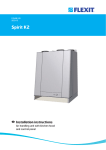
1
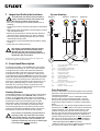
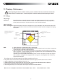
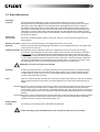
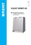
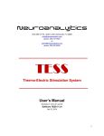
94108E-06
2005-10
FLEXIT S4 X/TT - A4 X/TT
S7 X/TT - A7 X/TT
User Manual
Air Handling Unit
Cabinet Models with Heat Recovery
Contents
1 Important Safety Instructions .............................................................3
2 Method of Operation - System ............................................................3
3 Operation - Control ..............................................................................4
3.1 Operation via a Kitchen Hood (A Models) ..........................................4
4 Troubleshooting ...................................................................................5
5 Cleaning - Maintenance ...................................................................... 6
5.1 Filters ....................................................................................................6
5.2 Other Maintenance .............................................................................. 7
6 Overview Drawings ..............................................................................8
6.1 Overview Drawing, S4 X/TT - A4 X/TT ...............................................8
6.2 Overview Drawing, S7 X/TT - A7 X/TT ..............................................8
7
Technical Data ..................................................................................... 9
7.1 Technical Data, S4 X/TT - A4 X/TT .....................................................9
7.2 Technical Data, S7 X/TT - A7 X/TT .....................................................9
8 Dimensioned Drawings ...................................................................... 10
9 Adjusting the Unit ................................................................................11
9.1 Adjustment .......................................................................................... 11
9.2 Control Card Adjustment Options ...................................................... 11
10 CE Declaration of Conformity ............................................................. 12
Symbols Used
This product has a number of symbols that are used to label the product itself and in the installation and user
documentation. Here is an explanation of some of the commonest symbols.
DANGER! ELECTRICITY
DANGER! DO NOT TOUCH
SUPPLY AIR
EXTRACT AIR
EXHAUST AIR
OUTDOOR AIR
HEATING THERMOSTAT
EXCHANGER/SUMMER
CASSETTE
Symbols for units/electric heating
TRANSFORMER
ADJUSTMENT
SUPPLY AIR
STAGE 2
TRANSFORMER
ADJUSTMENT
EXTRACT AIR
STAGE 2
Our products are subject to continuous development and we therefore reserve the right to make changes.
We also disclaim liability for any printing errors that may occur.
2
System Drawing
1 Important Safety Instructions
Supply air
To reduce the risk of fire, electric shock or
injury, read all the safety instructions and
warning texts before using the unit.
This unit is only designed to handle ventilation air in
buildings.
It must not be used to extract combustible or flammable
gases.
B1
Remove the power plug before commencing any service
and maintenance work.
EB1
Before you open the door, the unit must be dead and
the fans must be given time to stop (min. 2 minutes).
The unit contains heating elements that must not be
touched when they are hot.
The unit must not be operated without the filters being
in place.
Follow the user manual precisely.
Extract air Outdoor air
!
•
•
•
•
•
•
•
Exhaust air
EB2
F11
F21
F10
F20
FI2
To maintain a good indoor climate, comply
with regulations and avoid condensation
damage, the unit must never be stopped
apart from during service/maintenance or in
connection with an accident.
FI1
P1
HR-X
M1
B6
M2
All descriptions of Flexit S4 and S7 in this manual also apply to the
A models, except where specified otherwise.
2. Functional Description
B1
SUPPLY AIR TEMPERATURE SENSOR
B6
THERMOGUARD
F1, F2
OVERHEATING THERMOSTATS
F20, F21 OVERHEATING THERMOSTATS
FI1
SUPPLY AIR FILTER
FI2
EXTRACT AIR FILTER
EB1
HEATING ELEMENT
EB2
PREHEATING ELEMENT
HR-X
HEAT EXCHANGER CASSETTE
M1
SUPPLY AIR FAN
M2
EXTRACT AIR FAN
P1
PRESSURE GUARD (ACCESSORY)
* The following applies to the A models:
K
KITCHEN HOOD
DA4
DAMPER - KITCHEN HOOD
In the heat exchanger cassette HR-X, the cold outdoor
air and the warm extract air “cross” each other without
coming into direct contact with each other. With this
principle, 60-70% of the heat in the extract air will be
transferred to the supply air. In addition, a thermostatcontrolled heating element EB1 will ensure that the supply
air has the desired temperature. This supply air is passed
via ducts and valves to living rooms and bedrooms. The
extract air is extracted either from the same room or via
door gaps/overflow gratings to toilets and wet rooms.
The used air is passed via a duct system back to the
unit, emits heat as stated above and is blown out of the
building via a roof hat or wall grating.
Frost Protection
The unit is fitted with a special thermoguard for maximum
utilisation of the heat recovery function and maintenance
of balanced ventilation.
The thermoguard has a sensor rod B6 with a dual
function. This is located in the exchanger cassette’s
extract air duct and has an NTC element to check the
temperature and an indicator to register condensation
water.
If the extract air is dry, the thermoguard will ensure that
the unit works normally down to an outdoor temperature
of approximately -15°C. At lower temperatures, it will
produce an impulse to activate the frost protection
function. This function will be repeated periodically until
the exchanger cassette’s temperature is sufficient to
prevent freezing. If the extract air is damp, this function
will start at an outdoor temperature of approximately 8°C. The frost protection function operates as follows:
- The preheating element EB2 is activated.
- When this does not produce sufficient frost protection,
the speed of the supply air fan M1 is reduced.
Heating Elements
The heating elements are protected against overheating
by overheating thermostats F20/F21, which switch off
at 65°C. As an additional safety measure, overheating
thermostats F10/F11 switch off at 80°C. The overheating
thermostats can be reset manually by pressing the
white button. They are located at the front on the top
of the unit. They are accessible by opening the doors
and removing the plastic cover that covers the access
opening. See the label. The RESET button is located on
the innermost panel a little way inside the opening.
This is purely a ventilation system and not a
heating system. The home must be heated
in the normal manner. The heat gained from
heat recovery must be seen in relation to a
situation in which the extract air is blown right
out of the home without recovery.
3
3
Operation - Control
The speed of the fans in the unit is controlled from
a separately mounted SP 30 control switch. On
model S4, this is located at the bottom of the unit.
Depending on the operating situation, the fan speed
is set to the desired level.
MIN stage:
NORMAL stage:
MAX stage:
Red
Green
Yellow
Used when not as much ventilation
as normal is required.
Normal operating ventilation. This
is the position for daily operation.
Used when increased ventilation
is required in wet rooms or
throughout the flat. Must be
used during and for a while after
showering and clothes drying, for
example, to avoid condensation in
the ducts.
If the unit is in temporary automatic frost protection mode
in the winter, the unit will not react to a change in speed
before the frost protection function has ceased.
If there is a power cut, the unit will automatically be set to the Normal level and active
heating when it restarts. This means that the
heating element will provide heat if needed.
SP 30 Control Switch for Electronic Automatic Control
with a Thermoguard
This contains the following functions:
- Right pressure switch (fan symbol) to choose between
min, normal and max speeds with an indicator lamp to
show which speed stage is active.
- Left pressure switch (+ symbol) to choose heating
OFF/ON. This switch is used to switch heating off/on
(disconnected during the warm part of the year).
The heating thermostat (item 4/Chap. 6 General
Drawings) is factory-set to 20°C in the unit. It is
located inside the heating adjustment (item 4/page 8)
and should not be set to over 25°C. It can be adjusted
with a flat screwdriver. The sensor for the thermostat
is located in the supply air duct. Some heat loss up to
the valves must be expected where ducts pass through
a cold environment.
- Red lamp (!):
- Green lamp (+):
- Yellow lamp (°C):
3.1 Operation via a Kitchen Hood
(A Models)
Figure 1:
A – Knob for damper/timer
B – Pushbutton for light
Open the damper when preparing food. The damper closes
automatically after a maximum of 60 minutes or if you turn
the damper knob to
as shown in Figure 1. When the
timer is activated, the air handling unit is forced in addition
to the damper function.
Slow flash: Filter must be replaced
(provided that a pressure guard is
installed).
Fast flash: Overheating thermostat
triggered or thermoguard not
connected.
Permanently on: Both errors
This lights when the heating switch
is in the ON position:
This lights when the heating is
active (the element is heating).
4
4 Troubleshooting
FAULT
DO THE FOLLOWING
If the fans are not working or cannot
be adjusted
• Check that the power plug is correctly inserted in the power point.
• Check that the fuses in the electrical cabinet are switched on.
• The fire thermostat(s) (item nos. 7, 8/ Chap. 6 General Drawings) may
have been triggered. Remove the white plastic cover and press in the
white reset button.
• Check that the thermoguard (item no. 3) is connected.
If the supply air feels too cold
• Check that the heating switch is on and a summer cassette is not
loaded.
• The heating thermostat (item no. 4) can be set to a higher
temperature.
• Check that the thermoguard (item no. 3) is connected.
• The fire thermostat(s) (item nos. 7, 8) may have been triggered.
Remove the white plastic cover and press in the white reset button.
• Check that the heating switch is activated
If the air flow rate has been seriously
reduced
• The filters (item nos. 1, 2) may be clogged by dirt. Clean or replace
them. See under “Cleaning - Maintenance”.
• The grille in the outdoor air cap may be clogged. See under “Cleaning
- Maintenance”.
If none of this helps, please contact your supplier for service. Please state the serial number on the rating plate inside the unit
(open the door).
5
5 Cleaning - Maintenance
!
Before opening the door of the heat recovery system, switch off the heat, let the fans continue for
three minutes to remove hot air, remove the power and wait 2 minutes before opening the doors.
5.1 Filters
Why change
the filters?
Clean, filtered air is essential to ensure that your ventilation system contributes to a healthy
indoor environment. Therefore, the unit is fitted with replaceable filters. It is very important to
change them when they are dirty. Otherwise, the system may be damaged.
When should the
filters be changed? In general, the filters need to be changed once a year, preferably in the autumn (after the pollen
season). In areas with a lot of dust and contamination, the filters should be changed in the spring
and autumn.
Cabinet model filter location
(the drawing shows the left
model/the right model is
inverted)
Extract air filter:
Flat filter with cardboard
frame
Supply air
filter:
Prefilter and
compact filter
Thermoguard
Exchanger
cassette
How?
1. Switch off the unit as explained at the top of the page.
2. Pull the extract air filter (1) of type G3 flat filter with a cardboard frame (coarse filter) straight out
of the rail. Insert a new filter in the same place
3. Pull the supply air filter (2) out of the rail and insert a new filter in the same place. The supply air
filter is of type S4, a composite filter consisting of a prefilter in the form of a G3 flat filter (coarse
filter) and an F7 compact filter (fine filter).
The filter set must be installed in the following order, from the exchanger cassette (11): compact
filter - prefilter - steel grille. The supply air filter is of type S7, an F7 bag filter with several long
bags beside each other.
If the filters are not changed regularly, the following problems will occur:
1. Dirty filters cause increased air resistance and therefore reduce the supply of fresh, filtered air to the home.
2. Dirty, clogged filters reduce the quality of the indoor air.
3. Pollen particles that are caught in the filter may, over time, be released and distributed in the air blown in.
4. A poor indoor environment increases the risk of allergy problems.
5. Bacterial growth may occur in dirty filters and may be distributed in the air blown in.
Order nos. for a complete set of filters: S4 X (TT)/A4 X (TT)- 12318,
6
S7 X (TT)/A4 X (TT) - 12313
5.2 Other Maintenance
Exchanger
cassette:
Should be checked roughly once a year for dust and dirt in the air ducts. First remove the
thermoguard (3) and carefully pull the cassette (11) out. If cleaning is required, place it in a bowl
with warm soapy water (NB! not soda) and finally flush it through with warm water. Clean the
thermoguard separately with a dry cloth. When removing/installing the exchanger cassette, it is
important to ensure that both the cassette and the sensor rod are located correctly and that the
cable plug is inserted in the contact. The thermoguard must be located 6 cm from the top of the
exchanger cassette and in the centre of the exchanger cassette. Place it in the area visible beneath
the extract air filter (1).
Valves and
duct system:
The valves should be cleaned at least once a year. The duct system should be cleaned at least
every 10 years.
Outdoor air intake: Check once a year that the grille is not clogged with leaves, dust and dirt.
Roof hat:
Check once a year that the drainage gap at the bottom is not clogged with leaves. This applies only
if the system has a roof hat.
o
Summer operation: During the warm part of the year (outdoor air temperature over 15-20 ), there is no need to
recover heat. The exchanger cassette can be replaced with a summer cassette that is available as
an accessory. This is pushed into place where the exchanger cassette (11) is located. This allows
the outdoor air to enter the building directly without heat recovery taking place. The thermoguard
(3) must then be transferred to the summer cassette. Its location is shown on the label. NB! At the
same time, the heating must be switched off (press the left switch (+) on the control panel so that
the green light goes out) to avoid the heating element switching on unnecessarily.
Remember to reverse this again in the autumn
Drainage:
At the base of the unit there is a condensation water drain (14) that conducts condensation water
to the waste water drain. It is important that this drain is always open, in good condition and well
insulated where it is exposed to frost. It is recommended that you keep an eye on the drainage
system to avoid any leaks occurring.
Fans:
Item nos. 9 and 10. The fans normally do not need to be inspected. If necessary, they can be cleaned
with a small brush and compressed air, if possible. NB! Do not use water. Disassemble the fans as
follows:
S4 X/A4 X: Unscrew 2 screws at the front of each motor. One motor can then be pulled out. The other is located
within a distance piece. Pull the fan(s) carefully out of the track and then disconnect the electric
quick-release contact so that the fan is completely released. The motor and fan blades are removed
by unscrewing the 4 screws in the round motor plate and carefully pulling the motor out of the motor
housing.
S7 X/A7 X: Unscrew 2 screws at the bottom front of each fan housing. The entire fan housing can then be pulled
straight out. Disconnect the electric quick-release contact so that the fan housing is completely
released. The fan is now accessible from the open side.
Kitchen hood/
A model:
For cleaning, see the description in the kitchen hood manual.
!
Lack of cleaning as prescribed will increase the risk of fire in the event of an accident
7
6 Overview Drawings
6.1 Overview Drawing, S4 X/TT - A4 X/TT
Supply air
Extract air
Outdoor air
Item Part
no.
Exhaust air
Right model
8
7
6
5
1
2
1
2
3
4
5
6
7
8
9
10
11
4
9
10
12
13
14
15
12
4
3
13
11
14
15
G3 extract air filter
G3 + F7 supply air filter
Thermoguard
Heating adjustment
Preheater
Heating battery
Preheating fire thermostat (Reset)
Heating thermostat (Reset)
Supply air fan
Extract air fan
S4/TT exchanger cassette/cross heat
exchanger
Control switch
Control unit
Drainage outlet
Connection for kitchen hood
(only for A model)
6.2 Overview Drawing, S7 X/TT - A7 X/TT
Supply air
Extract air
Outdoor air
Exhaust air
Right model
12
8
7
5
6
2
1
3
4
13
11
10
9
14
15
8
Item Part
no.
1
2
3
4
5
6
7
8
9
10
11
12
13
14
15
G3 extract air filter
F7 supply air filter (bag)
Thermoguard
Heating adjustment
Preheater
Heating battery
Preheating thermostat (Reset)
Heating fire thermostat (Reset)
Supply air fan
Extract air fan
S7/TT exchanger cassette/cross heat exchanger
Control switch
Control unit
Drainage outlet
Connection for kitchen hood
(only for A model)
7 Technical Data
7.1 Technical data, S4 X/TT - A4 X/TT
S4 X
Rated voltage
Fuse
Rated current, total
Rated power, total
Rated power, electric batteries
Rated power, fans
Rated preheating power
Fan type
Fan motor control
Max. fan speed
Standard automatic control
Filter type (SUP/EXTR)
Filter dimensions, SUP (WxHxD)
Filter dimensions, EXTR (WxHxD)
Weight
Duct connection*
Height
Width
Depth
S4 X TT
230 V/50 Hz
10 A
8.7 A
1980 W
1650 W
2 x 165 W
975 W
F-wheel
Transformer
2230 RPM
SP30
F7/G3
255x220x50 mm
255x220x20 mm
51 kg
Dia. 160 mm
830 mm
900 mm
320 mm
230 V/50 Hz
10 A
8.7 A
1980 W
975 W
2 x 165 W
1650 W
F-wheel
Transformer
2230 RPM
SP30
F7/G3
255x220x50 mm
255x220x20 mm
56 kg
Dia. 160mm
830 mm
900 mm
320 mm
* For A-model kitchen hood: Dia. 125
All descriptions of Flexit S4 and S7 in this manual also apply to the A models, except where specified otherwise.
7.2 Technical data, S7 X/TT - A7 X/TT
S7 X
Rated voltage
Fuse
Rated current, total
Rated power, total
Rated power, electric batteries
Rated power, fans
Rated preheating power
Fan type
Fan motor control
Max. fan speed
Standard automatic control
Filter type (SUP/EXTR)
Filter dimensions, SUP (WxHxD)
Filter dimensions, EXTR (WxHxD)
Weight
Duct connection*
Height
Width
Depth
S7 X TT
230 V/50 Hz
16 A
10.4 A
2380 W
2000 W
2 x 190 W
975 W
B-wheel
Transformer
2465 RPM
SP30
F7/G3
394x223x250 mm
394x223x20 mm
72 kg
Dia. 200 mm
935 mm
950 mm
458 mm
230 V/50 Hz
16 A
10.4 A
2380 W
975 W
2 x 190 W
2000 W
B-wheel
Transformer
2465 RPM
SP30
F7/G3
394x223x250 mm
394x223x20 mm
78 kg
Dia. 200 mm
935 mm
950 mm
458 mm
* For A-model kitchen hood: Dia. 125
All descriptions of Flexit S4 and S7 in this manual also apply to the A models, except where specified otherwise.
9
8 Dimensioned Drawings
S4 X /S4 X TT
Left
Right
S7 X /S7 X TT
Right
Left
*All measures in mm
10
9 Adjusting the Unit
Before opening the door of the heat recovery system, switch off the heat, let the fans continue for three
minutes to remove hot air, remove the power from the unit and wait 2 minutes before opening the doors.
!
9.1 Adjustment
The speed of the unit at the normal stage must be set to the voltage specified in the “Documentation of Ventilation Data”
form that is enclosed with the ventilation drawings from the company responsible for project planning. Open the door and
unscrew and remove the cover of the automatic control compartment. The transformer is then visible (see picture below)
and the cables marked 1 2 3 (as shown on page 2) can be switched over to the specified voltage level.
Extract air Supply air
S4X/S4TT: The automatic control compartment is behind the cover at the bottom of the unit.
S7X/S7TT: The automatic control compartment is always on the right side.
11 12
150
13 14
170
120
10 9
8
Factory setting
Factory setting
15 16
190
105
6
60
5
170 V
170 V
18 19 20
230
85
7
150 V
150 V
4
3
2
0
1
Connection alternatives on the transformer
(label/connection points)
Transformer
9.2 Control Card Adjustment Options
Dipswitch
no.
OFF
ON
1
Heating is not affected
with frost protection
Heating is switched off
with frost
protection
2
Heating and preheating
function normally
Heating and preheating
are switched off at the min
stage
3
Not affected with nighttime Temperature is reduced
by 3°C with night-time
temperature reduction
temperature reduction
4
Not affected with
nighttime temperature
reduction
Fan speed is reduced to
low with nighttime temperature reduction
5
Preheating element is used
only for frost protection
Preheating element is also
used for heating
Must be in this position
Not used
6
Cross excanger unit control card
Dipswitch
Bold type shows the standard factory setting. All settings can be combined.
With the standard settings, the unit functions in such a way that heating is available if required with normal operation, while
heating is switched off with frost protection operation, when the preheating element takes over.
If both elements are required for heating in cold areas during frost protection operation, switch 1 must be switched to OFF.
Please note that the unit’s rated power will then increase with the power of the preheating element. On the L4/S4, 13 A fuses
must be used in such cases.
11
10 CE Declaration of Conformity
This declaration confirms that the products meet the requirements in the following Council Directives and standards:
89/336/EEC Electromagnetic compatibility (EMC)
73/23/EEC Low-voltage Directive (LVD)
EN 60335-1:94, + A11:95, + A1:96, +A1:96, +A12:96
EN 50081-1:92, EN 50082-1:92
Manufacturer:
Equipment group:
FLEXIT AS, Televeien 15, N-1870 Ørje
Ventilation units for installation in ducts
Type:
Falcon VGS400: 1998
VGS700: 1998
The product is CE-marked:
Shown in the list above
FLEXIT AS 02/05/2001
Pål J. Martinsen
General Manager
The right to give notice of lack of conformity applies to this product in accordance with the existing terms of sale,
provided that the product is correctly used and maintained. Filters are consumables.
The symbol on the product or on its packaging indicates that this product may not be treated as household waste. Instead it shall be handed over to
the applicable collection point for the recycling of electrical and electronic equipment.
By ensuring this product is disposed of correctly, you will help prevent potential negative consequences for the environment and human healthe,
which could otherwisw be caused by inappropriate waste handeling of this product. For more detailed information, please contact your local city
office, your household waste disposal service or the shop where you purchased the product.
Notice of lack of conformity as a result of incorrect or defective installation must be submitted to the installation company responsible.
The right to give notice of lack of conformity may lapse if the system is used incorrectly or maintenance is grossly neglected.
12
13
14
15
Flexit AS, Televeien 15, N-1870 Ørje www.flexit.no