1
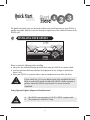
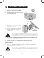
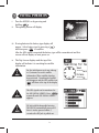
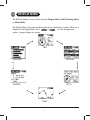
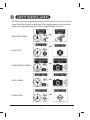
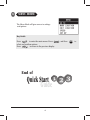
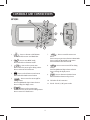
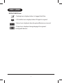
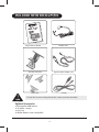
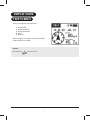
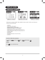
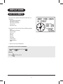
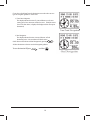
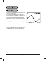
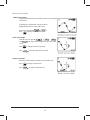
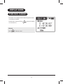
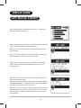
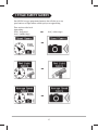
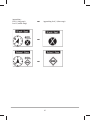
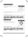
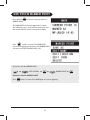
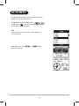
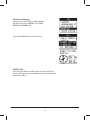
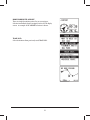
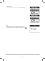
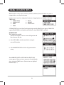
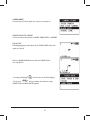
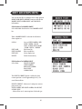
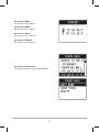
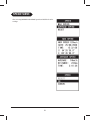
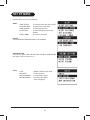
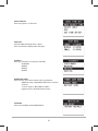
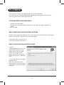
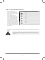
GPS501
Operating Manual
&
Quick Start
Guide
Global Positioning System
. Safety Warning System
. Breadcrumb Tracking
. Trip Computer
WARNINGS & NOTIFICATIONS
When using the GPS501 in a motor vehicle it is the user's
responsibility to ensure operating the GPS501 does not detract from
the safe operation of the vehicle.
For safety reasons it is not recommended that a driver change any
settings while in motion. Please come to a complete stop or have a
passenger make changes if necessary.
The latitude, longitude, and altitude indications on the display
depend on the MAP DATUM setting in the SET UP menu.
GPS signal reception can be affected by the location of satellites, tall
buildings, tunnels, bridges, etc. If the GPS501 is not receiving a
signal, you will need to change your location until a signal is
received.
The Global Positioning System is operated and maintained by the
US Government. The US Government is completely responsible for
the accuracy of the Global Positioning System.
The US Government reserves the right to make changes to the
Global Positioning System in accordance with the Department of
Defence civil GPS user policy and the Federal Radio navigation plan.
These changes along with poor satellite geometry could cause
inaccurate readings.
Do not leave the GPS501 in the car on hot sunny days. Alkaline
batteries can be damaged at high heat.
The GPS501 is not designed to be waterproof.
i
Quick Start
Guide
The Quick Start Guide pages are designed to allow you to install and start up your GPS501 as
quickly as possible, however it does not attempt to explain any of the advanced features of the
GPS501 unit.
INSTALLING YOUR GPS501
Please consider the following before installing.
! Always use the windshield mount provided when using the GPS501 in a motor vehicle.
! Avoid any position which may obstruct the deployment of any air bags or obstruct the
driver's view.
! Place your GPS501 in a position where it has an unobstructed view of the sky above.
If your vehicle has a UV screen affixed to part of the windshield this may
block or weaken GPS signals and affect the GPS501's ability to acquire a
position. Mount the GPS501 away from the UV screen area of the
windshield.
Using Cigarette Lighter Adaptor or Hardwire Lead
!
!
The GPS501 runs on positive 13.8V DC (12VDC), negative earth.
The positive wire is fused at 1 Amp.
ii
2
CONNECTING YOUR GPS501
i) Find the main unit, mounting bracket and
suction cups in the main box/package.
ii) Insert and locate the three suction cups on
to the mounting bracket.
C - Clip
iii) The GPS501 fits into the C-Clip which
can be rotated or turned.
iv) Once the viewing angle is set, turn the
lock knob clockwise to secure the
C-Clip position.
Lock Knob
Always check that the GPS501 is firmly locked when you place it
into the C-Clip.
v) Find the 12VDC cigarette lighter adaptor and insert the small plug into the 12VDC
power input on the side of the main unit.
vi) Insert the other end in to the cigarette lighter socket of your vehicle.
If using batteries:
i) Install 2xAA high capacity NiMH Rechargeable or Alkaline non Rechargeable
batteries into the back of the GPS501.
Do not mix Rechargeable or Alkaline non Rechargeable batteries.
iii
3
INITIAL POWER ON
i. Turn the GPS501 on by pressing and
holding
.
ii. The opening screen will display.
iii. If using batteries the battery type display will
appear. Select battery type by pressing
and then press
to confirm.
After the GPS signal is acquired the battery type will be remembered and this
screen will not display on next power on.
iv. The Trip Screen displays and the top of the
display will indicate it is searching for satellite
information.
For the initial power up it may take up
to 15 minutes to secure satellite
information. When satellite data has
been retrieved 'Searching for Satellite'
will disappear and the GPS satellite icon
will show at the top of the display.
The GPS signals can be monitored in
the GPS SIGNAL SCREEN. Press
repeatedly until GPS SIGNAL SCREEN
appears.
DC Jack with Rechargeable batteries.
The GPS501 automatically turns off if
there is no key pressed within 5
seconds after DC Jack is pulled out.
iv
4
DISPLAY MODE
The GPS501 displays a screen from either the Display Mode, Safety Warning Alerts
or Menu Mode.
The Display Mode is the main working mode where information is shown. There are 6
Displays in the Display Mode. Press
or
to cycle through these
modes. Sample displays are shown.
TRIP
GPS SIGNAL
TRIP DATA
POSITION
GO TO
TRACK
v
5
SAFETY WARNING ALERTS
The GPS501 has a pre-programmed memory that will alert you of any Fixed Speed
Camera, Red Light Camera or Black Spot. These displays pop up and an alert tone
sounds when approaching the alert location. Typical displays are shown.
C
RED LIGHT CAMERA
C
BLACK SPOT
C
AVERAGE SPEED CAMERA
C
SPEED CAMERA
C
SCHOOL ZONE
vi
6
MENU MODE
The Menu Mode will gives access to settings
and options.
Key Guide
Press
to enter the main menu. Press
select and confirm options.
Press
to return to the previous display.
End of
Quick Start
Guide
vii
and then
to
CONTENTS
Warnings & Notifications .............................................................................................................i
Quick Start Guide.......................................................................................................................ii
Installing Your GPS501...................................................................................................ii
Connecting Your GPS501...............................................................................................iii
Initial Power On.............................................................................................................iv
Display Mode ......................................................... ....................................................... v
Safety Warning Alerts .......................................... ..........................................................vi
Menu Mode ..................................................................................................................vii
Contents.....................................................................................................................................1
Introduction...............................................................................................................................3
Features .....................................................................................................................................3
Controls and Connections..........................................................................................................4
Indicators...................................................................................................................................5
Included With Your GPS501 .......................................................................................................6
DISPLAY MODES .............. .........................................................................................................7
Trip Screen.....................................................................................................................7
Trip Data Screen.............................................................................................................8
Go To Screen ..................................................................................................................9
Track Screen.................................................................................................................11
Position Screen.............................................................................................................13
GPS Signal Screen .......................................................................................................14
3 Stage Safety Alerts..................................................................................................................15
Over Speed Alert.......................................................................................................................17
Fatigue Alert ............................ ................................................................................................17
One Touch Marked Point..........................................................................................................18
1
CONTENTS
MENU MODE .......................................................................................................... 19
Go To Menu ...................................................................................................20
Mark Location Menu .................................................................................... 24
Edit Location menu ..................................................... ................................ 26
Speed Menu ................................................................. ................................ 28
Set Up Menu.................................................................................................. 29
Dimmer .................................................................................................................. 31
NMEA Output .......................................................................................................... 31
PC Updates .................................................................. ........................................... 32
Maintenance ............................................................................................................34
Troubleshooting .......................................................................................................34
Warranty ....... ...........................................................................................................35
2
INTRODUCTION
The Uniden GPS501 is designed to provide you with years of trouble free service. It's
rugged components and materials are capable of withstanding harsh environments.
We are certain that you will enjoy your GPS501. Please read this operating Manual
carefully to ensure you gain the optimum performance of the unit.
FEATURES
! 2” Clear View White LCD Adjustable
backlight and contrast
! GPS Satellite signal information
! Multiple GPS datum and position
formats
! Selectable Nautical, Metric or Statute
! Time and Date
! Selectable High Accuracy GPS Mode
! NMEA GPS data output
! Long battery life Battery operation
including battery save mode
! Internet update via USB port for safety
warning locations
! Internet Firmware update for feature
upgrades
! Application software to edit and update
your data via PC
! Customizable Safety Warning System
for Australia and New Zealand
! 3 Stage visual warning system with
voice alert
! Speed Camera Warning
! Red Light Camera Warning
! Black Spot Warning
! School Zone Warning
! Over Speed Alert
! Fatigue Alert
! Mark and Edit your own safety
locations
! Individually Adjustable volumes
! Individually adjustable Alert distances
! Automatically adjusting Alert distances
referenced to speed
! GPS Position with emergency voice
readout
! GPS direction to more than 10,000
Australia / New Zealand cities, suburbs
and Points of Interest(POI)
! Customizable Trip Computer
! Heading, Speed, Bearing, Time to Go,
Distance to Go, Trip Time, Trip
Odometer, Average Speed, Max Speed,
GPS Location, Altitude.
! Compass
! Route tracking with Voice Assistance
! Mark location with name tag and icon
! One touch quick location marking
3
CONTROLS AND CONNECTIONS
GPS501
1
2
3
4
5
10
6
9
8
1.
- Press to shortcut to GO TO Menu
Press and hold to start or save TRACK data
2.
- Press to enter MENU mode
Press and hold to set Dimmer On/Off
3.
- Press to select a menu item
Press to move the cursor up for editing a Name
Press to zoom out for Track Screen
4.
- Press to select function in each menu
Press and hold to Mark current location
5.
- Press to move the cursor right for
editing a Name
Press for alphabetical skip in Name selection
Press to change the display screen
6.
11
7
7.
- Press to cancel the most recent
action
Press to return to previous selection in Menu Mode
Press to exit from Menu Mode on top menu
Press and hold to turn Power On/Off
8.
- Press to move cursor left for editing
a Name
Press for alphabetical skip in Name selection
Press to change the display screen
9.
- Press to shortcut to Position Screen
Press and hold to shortcut to Trip Screen
10. USB socket for PC connection
11. DC12V - DC12V (13.8V) power socket
- Press to select a menu item
Press to move the cursor down for editing a Name
Press to zoom in for Track Screen
4
INDICATORS
DISPLAY MODE Icons
- Tracking Icon is displayed when it is logging Track Data.
- GPS Satellite Icon is displayed when GPS signal is acquired.
- Battery Icon is displayed when the optional Batteries are inserted.
- Charge Icon is displayed during charging of the optional
rechargeable Batteries.
5
INCLUDED WITH YOUR GPS501
GPS501 Owners Manual
Hardwire lead
Windscreen Bracket
Cigarette Lighter Adaptor Lead
Suction cups
USB cable
If any of these items are missing from the box, contact your dealer immediately.
Optional Accessories
!
!
!
!
Rechargeable NiMH batteries
AC adaptor / charger
Carry case
Alkaline Batteries (non rechargeable)
6
DISPLAY MODE
TRIP SCREEN
The Trip Screen displays this information:
!
!
!
!
!
Time and Date
Heading (Compass)
Bearing (Arrowhead)
Speed
Odometer
When GPS signal is not acquired "Searching for Satellite"
scrolls instead of time and date.
Shortcut
Press and hold
from any screen.
7
DISPLAY MODE
TRIP DATA SCREEN
The Trip Data Screen displays LARGE (1 DATA), MIDDLE (2 DATA) or SMALL (5 DATA) items of information.
Selection is from this information:
! HEADING
! SPEED (The running speed)
! BEARING (Bearing to the destination)
! TIME TO GO (Estimated time to the destination)
! DISTANCE TO GO (Distance to the destination)
! TRIP TIME (The time counted after turning the power on)
! TRIP ODOMETER (The mileage after turning the power on)
! AVERAGE SPEED
! MAX SPEED
! LOCATION (Information of current location)
! ALTITUDE
Key Guide to TRIP DATA customization
C
SET UP
C
C
TRIP DATA
Shortcut
Press
from the TRIP DATA display.
8
C
DISPLAY MODE
GO TO SCREEN
The Go To Screen displays information for direction to a
destination.
! Name of the destination
! Heading (Compass)
! Bearing (Arrowhead)
! Time to go
! Distance to go
The destination can be chosen from the following options:
! City
! POI (Points of Interest)
! Nearest POI
! Home*
! Work*
! Hotel*
! Airport*
! Track Data*
! Marked Point*
! Off
* These are user stored destinations.
Key Guide to select a GO TO destination
C
C GO TO C
Shortcut
Press
from any screen.
9
If you select a Track Data from the destination menu then there are two
types of Navigation guidance to select from:
1) Turn Point Navigation.
The display indicates direction of, time and distance to the next
turning point. Voice assistance will also be active. If GPS501 comes
close to the Turn Point, it displays this display and Next Turn point
alternatively.
2) Goal Navigation.
The display indicates direction, time and distance to final
destination point. Voice assistance will also be active.
Switch between Turn Point and Goal Navigation by pressing
All other destination selections use Goal Navigation guidance.
To turn destination Off press
and then
10
.
.
DISPLAY MODE
TRACK SCREEN
The Track Screen displays breadcrumb tracking for when you
want to create and track a route.
The Track Screen can also display previously stored track
routes as a destination (used in this case as a GO TO screen) .
The arrowhead for current position and direction, and the
scale of the screen is displayed. The North up icon is displayed
for North up screen. (There is no icon for Heading up screen.)
During the logging of new Track Data, the route of the logged
Track Data (dotted points) shows.
When a Track Data is set as the GO TO destination, the Track
screen is used and will show the track of Track Data which is
to be followed.
If logging a new Track Data while a GO TO Track Data is active
then the Track Data which is set to Destination is displayed.
11
There are 3 screen modes:
Normal screen mode If map orientation has been set to North Up then current position is centre
of the screen.
If Heading Up is selected then current position is
displayed just below the centre of the screen.
Zoom in/out by pressing
or
.
Press
to change to Scroll screen mode.
Scroll screen mode Scroll the screen by pressing
,
,
and
. The scope indicator appears in the centre of the
screen.
Press
Press
to change to Zoom screen mode.
to change to Normal screen mode.
Zoom screen mode Zoom in/out of the position centred on in the Scroll screen.
Press
Press
to change to Scroll screen.
to return to Normal screen.
12
DISPLAY MODE
POSITION SCREEN
The Position screen displays Position Data (Longitude/Latitude
or Grid data) and altitude.
Position Data is announced when
is not announced.)
is pressed. (Attitude
Shortcut
Press
from any screen.
13
DISPLAY MODE
GPS SIGNAL SCREEN
The GPS signal strength and satellite number for up to 5 satellites are
displayed with this screen option.
When a GPS signal is not acquired for 5 minutes the GPS501 displays the
prompt "ARE YOU INDOORS?" with YES/NO selection.
When "YES" is selected (using indoors), the GPS501 will return to the
previous display.
When "No" is selected and there is no date information from GPS, GPS
performs GPS Reset and return to the previous display.
When "NO" is selected (using outdoors), the GPS501 will display the
prompt "HAVE YOU MOVED 100 MILE/KM SINCE LAST USE?" with
YES/NO selection.
When "YES" is selected (moved), the GPS501 performs GPS Reset and
returns to the previous display.
When "NO" is selected (not moved), the GPS501 will display the prompt
"IS TODAY DD/MM/YYYY ?" with YES/NO selection. Here, "DD/MM/YYYY"
is the date from acquired with the GPS antenna.
When "YES" is selected (the date is correct), the GPS501 will return to the
previous display and it continues searching. When "NO" is selected (the
date is incorrect), the GPS501 performs GPS Reset and returns to the
previous display.
14
3 STAGE SAFETY ALERTS
Your GPS501 has a pre-programmed memory that will alert you to any
speed camera, red light camera or black spot you are approaching.
There are three Alert levels.
Approaching....
Level 1 (long range),
Level 2 (middle range)
C
Level 3 (short range)
C
C
C
15
Approaching....
Level 1 (long range),
Level 2 (middle range)
C
Approaching Level 3 (short range)
C
C
16
OVER SPEED ALERT
The GPS501 will sound and display an alert if you run over the
Alert Speed setting.
When the running speed is over the Alert Speed, the Over Speed Alert Tone sounds and "Slow
Down!" is announced every 20 seconds.
Key Guide to Over Speed Alert setting
C
C
SET ALERT SPEED C
SET UP
C
ALERT
C
C
C
C
FATIGUE ALERT
The GPS501 can sound an alert after continuous use for a
preset time. The preset time can be set in 1hr steps.
Key Guide to Over Speed Alert setting
C
C
FATIGUE TIMER C
SET UP
C
ALERT
17
ONE TOUCH MARKED POINT
Press and hold
MARKED POINT.
to save the current position as a
The MARK POINT saved screen appears for 5 seconds
after which the entry is saved with the current time and
date and the GPS501 returns to the previous display.
Press
within 5 seconds of the MARK POINT
saved screen appearing to shortcut to the MARKED POINT
edit menu (see EDIT LOCATION MENU p26).
Key Guide to edit the MARKED POINT
C
EDIT LOCATION
C
C
MARKED POINT
Shortcut to edit the MARKED POINT
Press
within 5 seconds of the MARK point save screen appearing.
18
C
MENU MODE
MENU Mode can be accessed from any Display Screen
by pressing
.
Key Guide
Press
or
to highlight desired options and press
19
to select.
GO TO MENU
The GO TO menu provides access to the database of preinstalled or user saved destinations.
To highlight the desired selection, press
,
and then press
to set. The navigation begins and the
GO TO display screen will appear.
CITY
Select the State (State of Australia or New Zealand) to
select a city from.
In the CITY menu press
alphabetical groups.
or
to skip
20
POI (Points Of Interest)
Select the type of POI. The pre-installed database
may have types such as AIRPORT, GAS STATION,
HOSPITAL and PARKING LOT.
Select desired POI from the name list and set.
NEARAST POI
Select the type of POI as per POI selection. The three POI closest
to your current position are then displayed. Select desired POI from
the name list and set.
21
HOME/WORK/HOTEL/AIRPORT
These are single destination points for you convenience.
Selection immediately begins navigation in the GO TO display
screen. An example of the AIRPORT selection is shown.
TRACK DATA
Select destinations from previously saved TRACK DATA.
22
MARKED POINT
Select destinations from previously saved MARKED POINTS.
OFF
Select this option to cancel a current GO TO operation.
Alternatively from the GO TO display mode and then press
23
.
MARK LOCATION MENU
Mark Location is used to store in memory a location, which may be used in future as a point to
navigate back to, or safety alert location.
Locations can be saved as a single point location or as logged points in a
TRACK route.
! MARKED POINT
! HOTEL
! CAMERA POINT
! AIRPORT
! HOME
! TRACK START*
! WORK
*If TRACK START is selected then Track Logging begins and the TRACK Screen appears. TRACK END
replaces TRACK START in the Mark Location menu list when TRACK START is selected.
MARKED POINT
Three options are provided.
Select the first option to save the current GPS position with
basic reference and date.
! Select NEW NAME to edit the name before saving the
current GPS position.
! Select MARK NEW POINT to edit the GPS position before
saving.
After MARK NEW POINT or NEW NAME the SELECT ICON
screen appears. Choose an icon to represent the marked point
when viewing the TRACK screen. (Various icons are displayed
instead of A,B,C ...)
24
CAMERA POINT
Select the type of camera point you want to save position as.
HOME/WORK/HOTEL/AIRPORT
Select to mark current position as HOME, WORK, HOTEL or AIRPORT.
TRACK START
TRACK logging begins immediately in the TRACK SCREEN when this
option is selected.
Return to MARK LOCATION menu and select TRACK END to
view end options.
- Pressing and holding
can also start or end Track logging.
- If you press
during tracking, the menu for saving
(TRACK SAVE and TRACK CLEAR) appears.
25
EDIT LOCATION MENU
You can edit the GPS co-ordinates of the single position
HOME/WORK/HOTEL/AIRPORT locations and edit the
MARKED POINT/CAMERA POINT and TRACK DATA
information.
Edit location of a MARKED POINT
Select individual data from the saved MARKED POINT
list.
When a MARKED POINT is selected the edit menu
shows options to:
SAVE AS
EDIT NAME
EDIT LOCATION
EDIT ICON
DELETE
Save as SPEED CAMERA / RED
LIGHT CAMERA / BLACK
SPOT / SCHOOL ZONE/ HOME
/ WORK / HOTEL / AIRPORT
Edit Name Tag
Edit co-ordinates
Select display icon
Delete from memory
Edit location of a CAMERA POINT
Select from:
DELETE CURRENT
SPEED CAMERA
RED LIGHT CAMERA
BLACK SPOT
SCHOOL ZONE
The DELETE CURRENT option is valid only when
current position is in the Approaching Level 3 of a
saved Camera Point.
DELETE CURRENT - delete user's and preset camera
point one by one.
SPEED CAMERA, RED LIGHT CAMERA, BLACK SPOT,
SCHOOL ZONE
- delete all the user's camera points of selected type.
26
Edit location of HOME
Directly edit the GPS co-ordinates.
Edit location of WORK
Directly edit the GPS co-ordinates.
Edit location of HOTEL
Directly edit the GPS co-ordinates.
Edit location of AIRPORT
Directly edit the GPS co-ordinates.
Edit location of a TRACK DATA
Select individual DATA from the saved TRACK DATA list.
27
UHF CHANNELS
SPEED
MENU & FREQUENCIES
After reviewing MAXIMUM and AVERAGE speeds use RESET to clear the
readings.
28
SET UP MENU
From the SET UP you can set the following:
ALERT
ALERT SETTING
SET ALERT SPEED
ALERT DISTANCE
SET DISTANCE
FATIGUE TIMER
Set (Camera Point) Safety Alerts On/Off
Set speed for Over Speed Alert
Set from Manual or Auto
Set when Manual selected for Alert
Distance
Set in 1hour increments
DISPLAY
Set LCD BACKLIGHT, BACKLIGHT TIME or LCD CONTRAST
VOLUME SETTING
Set from three options. BEEP VOLUME, VOICE VOLUME or ALERT VOLUME
Each option can be set between 0 to 7.
UNITS
UNITS
MAP DATUM
POSITION FORMAT
MAP ORIENTATION
- METRIC, STATUTE or NAUTICAL
- Set from 6 options
- Location format settings
- Determines how TRACK
Screen is displayed
29
LOCAL TIME SET
Select from options to set local time.
TRIP DATA
Customize TRIP DATA display from 3 options.
Select desired DATA to display within each option.
ACCURACY
Select type of situation to use GPS501 comfortably.
STATIONARY
WALKING
DRIVING
BOATING
POWER SAVE MODE
Select for power conservation measures when using batteries.
ALWAYS ON setting in BACKLIGHT TIME menu is treated as
2 minutes.
"seconds" display in TRIP SCREEN is hidden.
Logging interval in Track Data becomes longer.
INITIALIZE
Select from GPS RESET and FACTORY DEFAULT.
30
DIMMER
Press and hold
to toggle DIMMER On or Off.
Dimmer level is fixed to level 1 of LCD backlight. So even if the LCD
backlight is off, dimmer is level 1.
NMEA OUTPUT
The GPS501 can be used as a GPS unit by connecting with a PC or other device which can
interpret NMEA version (3.01) data.
The GPS501 continuously outputs NMEA sentences via the USB socket. This is only
interrupted if it receives a connection request from the Update Software, see PC UPDATES
page 32. (The NMEA output continues after it receives the cancel request.)
31
PC UPDATES
You may update the GPS501' s firmware or Camera Point, City Data and POI Data.
You can also back up or edit HOME, WORK, HOTEL, AIRPORT, Marked Point and Track Data on your PC.
Connect the GPS501 to a PC with the supplied USB cable.
PC REQUIREMENTS FOR DOWNLOADING
-
Pentium II equivalent or higher
Operating System: Win98second edition, Win2000 or XP. This model also supports "Windows ME".
USB Port
Internet Capable
HOW TO DOWNLOAD THE APPLICATION SOFTWARE
Visit the Customer Support/Downloads page on the Uniden website below and download the "GPS501 Updater
Software" and "USB Driver" zipped files. Unzip the downloaded files.
For Australian model: www.uniden.com.au
For New Zealand model: www.uniden.co.nz
HOW TO SETUP THE APPLICATION SOFTWARE
1. Run the
"GPS501UpdaterInstaller.msi" file in the
updater folder to install the GPS501
Updater Software. The GPS Updater
Software icon will appear on the
desktop. Do Not click to start updater
software until USB Driver is installed in
step 2.
2. Connect the USB cable to the GPS501
and then to the PC.
When "New USB Hardware Found"
appears follow the instructions to point
to the USB driver data downloaded from
the website.
32
HOW TO USE THE APPLICATION SOFTWARE
1. Click on the GPS501 Updater
Software icon on the desktop. The
prompt "Do you connect to the Web
Server?" appears.
Click Yes and the updater will
retrieve information from the web
server and the GPS501 and display it
in the Web Access window. If the
selected data (Camera, City, POI or
Firmware) on the web server is from
a newer version then you can update
the GPS501 by clicking on Execute.
Click No and the updater window will
open the Web Access window with no
data information.
2. You may click on the other window options on the left side panel to view and edit data you have saved on the
GPS501.
Always close the GPS501 Updater application software before disconnecting the GPS501
from the PC.
33
MAINTENANCE
Please follow these guidelines to ensure your GPS501 is well maintained.
Use only a dry cloth to clean GPS501. (The GPS501 is not designed to be waterproof.) . If you clean the LCD, be
as gentle as possible.
TROUBLESHOOTING
If your GPS501 does not perform to your expectations, try the suggestions listed below.
Unit does not operate:
* Check the power cord. Be sure the connectors are properly installed.
* Be sure ignition key is ON or in the accessory position.
* Fuse out. Check and replace.
* Check power to lighter socket. Vehicle electrical problem exists.
* Clean cigarette lighter socket.
No GPS Detection.
* Make sure the GPS501 is facing upright and the top of the unit (where the
GPS receiver is located) is not obstructed.
* Relocate the unit clear of any obstruction from the sky view.
Will not charge.
* Have you selected Rechargeable battery at battery menu mode? (Battery
menu mode appears if you take the batteries out or put batteries in.)
* Make sure environment for charging is not at high heat levels.
* The batteries have been fully charged already.
* Make sure the batteries are not defective.
* Voltage shortage of DC Jack.
Batteries not lasting.
* Use high quality alkaline batteries.
* Extend the battery life by using an optional cig lead-AC/DC charge pack
34
WARRANTY
UNIDEN GPS501 GPS Navigation System
Limited One Year Warranty
Please keep your sales docket as it provides evidence of warranty.
Warrantor: Uniden Australia Pty Limited ABN 58 001 865 498
Uniden New Zealand Limited
Warranty only available in original country of purchase
ELEMENT OF WARRANTY:
Uniden warrants to the original retail owner for the duration of this warranty, its GPS501 Navigation System (herein after referred to
as the Product), to be free from defects in materials and craftsmanship with only the limitations or exclusions set out below.
WARRANTY DURATION:
This warranty to the original retail owner only, shall terminate and be of no further effect 1year (12 months) after the date of
original retail sale. This warranty will be deemed invalid if the Product is;
(A) Damaged or not maintained as reasonable and necessary,
(B) Modified, altered or used as part of any conversion kits, subassemblies, or any configurations not sold by Uniden,
(C) Improperly installed,
(D) Repaired by someone other than an authorized Uniden Repair Agent for a defect or malfunction covered by this warranty,
(E) Used in conjunction with any equipment or parts or as part of a system not manufactured by Uniden, or
(F) Where the Serial Number label of the product has been removed or damaged beyond recognition.
Warranty only valid in the country of original retail/sale.
PARTS COVERED:
This warranty covers for one (1) year, the Product and included accessories.
STATEMENT OF REMEDY:
In the event that the Product does not conform to this warranty at any time while this warranty is in effect, the warrantor at its
discretion, will repair the defect or replace the Product and return it to you without charge for parts or service. This warranty does
not provide for reimbursement or payment of incidental or consequential damages. This EXPRESS WARRANTY is in addition to and
does not in any way affect your rights under the TRADE PRACTICES ACT 1974 (Cth) (Australia) or the CONSUMER GUARANTEES ACT
(New Zealand).
PROCEDURE FOR OBTAINING PERFORMANCE OR WARRANTY:
In the event that the Product does not conform to this warranty, the Product should be shipped or delivered, freight pre-paid, with
evidence of original purchase (e.g. a copy of the sales docket), to the warrantor at:
UNIDEN AUSTRALIA PTY LIMITED
Service Division
345 Princes Highway,
Rockdale, NSW 2216
Fax (02) 9599 3278
www.uniden.com.au
UNIDEN NEW ZEALAND LIMITED
Service Division
150 Harris Road,
East Tamaki, Auckland
Fax (09) 274 4253
www.uniden.co.nz
Customers in other states should ship or deliver the Product freight pre-paid to the nearest Uniden Authorised Repair
Centre. (Contact Uniden for the Warranty Agent nearest you.)
35
FOR PURCHASING A UNIDEN PRODUCT
© 2007 Uniden Australia Pty Limited Uniden New Zealand Limited
Printed in China USZZ01078ZA(0)