1
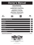
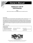
9
TRIPPaUTE
POWER PRorEcTloN
N
1111 W. 35th Street
Chlcago, IL 60609 USA
Customer Support: (773) 869-1234
Application Services: (773) 869-1236
www.tripplite.com
1
Capyrighl 0 MOI Tripp tile. All ri@umrved. Smam3nlieN is a rcgisterrd trademark of Tripp Lite.
This manual contains important instructions and warnings that should be followed
during the installation, operation and storage of all Tripp Lite SmartOnline UPS
Systems.
UPS Location Warnings
Install your UPS indoors, away from excess moisture or heat, dust or direct
sunlight.
Install your UPS in a structurally sound area. Your UPS is extremely heavy; take
care when moving and lifting the unit.
Only operate your UPS at indoor temperatures between 32" F and 104" F (between
0"C and 40" C). For best results, keep indoor temperatures between 62" F and
84" F (between 17" C and 29" C).
Leave adequate space around all sides of the UPS for proper ventilation: 12 in. (30
cm.) clearance at the rear; 4 in. (10 cm.) at sides and on top.
Do not install the UPS near magnetic storage media, as this may result in data
conuption.
UPS Connection Warnings
The power supply for this unit must be single phase rated in accordance with the
equipment nameplate. It also must be suitably grounded.
Equipment Connection Warnings
Do not use M p p Lite UPS Systems in life support applications in which a malfunction or failure of a Tripp Lite UPS System could cause failure or significantly
alter the performance of a life support device.
Connect your UPS's Grounding Terminal to a grounding electrode conductor.
The SUGK contains its own energy source (battery). The output terminals may be
live even when the UPS is not connected to a n AC supply.
Battery Warnings
Your UPS does not require routine maintenance. Do not open your UPS for any
reason. There are no user-serviceable parts inside.
Because the batteries present a risk of electrical shock and bum from high shortcircuit current, batteries should be changed only by trained service personnel
observing proper precautions. Replace the existing batteries with the same number
and type of new batteries [(Sealed Lead-Acid) SU6K (twenty 12V/7AH batteries);
SUlOK (forty 12V/7AH batteries)]. Do not open the batteries. Do not short or
bridge the battery terminals with any object.
The UPS batteries are recyclable. Refer to local codes for disposal requirements, or
if in the USA call 1-800-SAV-LEAD (1-800-728-5323) for complete recycling
information. Do not dispose of the batteries in a fire.
Connect only Tripp Lite battery packs to your UPS's external battery connectors.
Do not operate your UPS without batteries.
Fuses should be replaced only by factory authorized personnel. Blown fuses
should be replaced only with fuses of the same number and type.
Potentially lethal voltages exist within this unit a s long a s the battery supply is
connected. Service and repair should be done only by trained personnel. During
any service work, the UPS should be tumed off or put into manual bypass (see pg.
12).
During "hot-swap" battery replacement (when the UPS is on manual bypass and
connected equipment is turned ON) your UPS will be unable to provide battery
backup in the event of a blackout.
Do not connect or disconnect the battery cabinets while the UPS is operating from
the battery supply or when the unit is not in bypass mode.
Familiarize yourself with the location and function of the front and rear panel
features before installing and operating your UPS.
FRONT PANEL
0
0
0
0
UPS SYSTEM
,
5
1. "ON/OFFn Switch: This momentary rocker switch turns the UPS System's inverter
ON and OFF.
2. "SELECT" Button: This button performs two functions: it allows you to browse
through different power readings on the LCD Display by momentarily pressing the
button; it also allows you to silence the UPS alarm by pressing and holding the button
for 3 seconds.
3. LCD Display: This backlit (16x2 character) dot matrix display indicates a wide range
of UPS operating conditions and diagnostic data. It will illuminate after you have
properly completed installation and start-up and after the "ON/OFFmSwitch is turned
ON.
4. " I / P (Input) LED: This green light will illuminate constantly to indicate a n AC input
supply is present.
5. "AC/DC" (Converter) LED: This green light will illuminate constantly to indicate the
UPS's AC/DC converter is activated.
6. "DC/ACW(Inverter) LED:This green light will illuminate constantly to indicate the
UPS's DC/AC inverter is activated.
7. " O / P (Output) LED: This green light will illuminate constantly to indicate your UPS
is supplying AC power to connected equipment.
8. "BYPASS"LED: This green light will illuminate when the UPS is providing filtered
mains powerwithout engaging its converter or inverter. Connected equipment will not
receive battery power in the event of a blackout.
9. "BATTERY" LED: This red light will illuminate when the UPS is discharging the
battery to provide connected equipment with AC power. An alarm will sound which
can be cancelled by pressing and holding the "SELECT" switch for 3 seconds. The
alarm will be cancelled, but the LED will remain illuminated.
SUBP
REAR PANELS
1. Manual Bypass Switch:This red and yellow dial is used in one step of putting the UPS
in "BYPASS"mode, which must be done before performingany maintenance on the UPS
with the connected load supported. (See page 12 for step-by-step instructions for going
into "BYPASS.")While this switch is on "BYPASS." connected equipment will receive
filtered AC mains power, but will not receive battery power in the event of a blackout.
2. Input Terminal Block: Use these terminals to connect your UPS to the AC main
power input. Unscrew and remove terminal block plate for access. The optional SUBP
battery pack's IEC-320 connector accepts i t s charger's input power cord.
3. Output Terminal Block: Use these terminals to connect your UPS to equipment.
A plate covering the terminal block must be unscrewed and removed for access.
4. Input Voltage Select Terminal Block: Use these terminals to set your UPS's to
receive your 208V AC or 240V AC line voltage. A plate covering the terminal block
must be unscrewed and removed for access.
5. External Battery Connector: Use this to connect Tripp Lite Battery Packs. The
SUlOK requires a SUlOKBP or SUBP to operate; additional SUBP's can be added to
SU6K or SUlOK systems for extra runtime. Refer to instructions available with the
optional SUBP Battery Pack for connection instructions and safety warnings.
6. Exhaust Fan: This cools and ventilates the inside of the UPS.
7. AS-400 Interface Port: This female DB9 port connects your UPS to a n IBM AS-400
computer interface via the AS-400 Cable included. It uses AS-400 communications
to report UPS status and power conditions. Using this port, an IBMAS-400 computer
can automatically save open files and shut down i t s operating system during a
blackout. See "Communications." pg. 13. for details.
8. "Smart" -232
Interface Port: This female DB9 port connects your UPS to a
workstation or server. It uses RS-232 communications to report UPS and power
conditions. It is used with Tripp Lite software and the included RS-232 Cable to
monitor and manage network power and to automatically save open files and shut
down equipment during a blackout. See "Communications." pg. 13. for details.
9. Dry Contact Interface Port: This female DB9 port sends contact-closure signals to
indicate line-fail and low-battery status. See "Communications." pg. 14, for details.
10. Accessory Slot: Remove the small cover panel and use optional accessories
to remotely control and monitor your UPS. Contact Tripp Lite Customer Support for
more information and a Hst of available SNMP. network management and connectivity products.
11. "BatteryStart"Switch:This momentaryrocker swltch allowsyou to "cold-start" your
UPS and use it a s a stand-alone power source when utility-supplied AC power is not
present. The switch enables the UPS's DC/AC Inverter. Before "cold-starling" your
UPS, make sure your UPS and external battery cabinets are properly installed. Press
and hold the "Battery Start" Switch and then press the "ON/OFF" switch to turn your
UPS ON. To turn it OFF after "cold-start," press the "ON/OFF" Switch.
12. Battery Fuses (SU6K & SUBP's Only):The 30A/600V fuses protect your connected
battery or battery bank.
13. AC Input Breakers: One double-pole circuit breaker controls input power to the UPS.
14. AC Output Breaker: Triple-pole circuit breakers control output power from the UPS.
15. Remote "Emergency Power OFF" Connector: This R J l l modular jack allows
remote emergency shutdown. See "Communications,"pg. 14. for details.
16. Inverter Operation DIP Switches: Behind this removable panel are four DIP
Switches that should be set to match your input voltage and input frequency. Your
input voltage and frequency DIP switch settings MUST match your input. Your UPS
WILL NOT CONVERT the voltage or frequency.
17. Grounding Terminal: This terminal connects to a grounding electrode conductor.
IT IS NOT SAFE TO OPERATE YOUR UPS WITHOUT CONNECTING IT. The
recommended conductor size is 8 AWG based on the UL 1778 standard.
18. Stabiltzers: These supports extend to keep your UPS from rolling or tipping.
INVERTER OPERATION DIP SWITCH
SETTINGS (SUIOKPM SHOWN)
Using a small tool, set the four Inverter Operation DIP Switches (located on the rear panel of
your UPS, see pg. 4-5 for location) to match
your input voltage, input frequency a n d
desired operational mode.
InDut Voltage Selection
(D~P
switch& # 1 ~r #2)
(Input Voltage Select Terminal Block)
These DIP switches and the Input Terminal
Select Block must BOTH be set to match your
input voltage. Your UPS WILL NOT CONVERT
the voltage.
J n ~ uVolt=
t
240V
DIP Switch Position
Input Voltage
Select Terminal Block
#1 DOWN & #2 DOWN
Invut Frequencv Selection
(DIP Switch #3)
Your Input Frequency setting MUST match your input frequency. Your UPS WILL NOT
CONVERT the frequency.
Input Frequency
DIP Switch Position
6 0 Hz
#3 DOWN
Overational Mode Selection
(DIP Switch #4)
The "On-Line" Mode provides on-line operation with zero transfer time. The "Economy"
Mode provides line-interactive operation for increased efficiency when on-line protection
is unnecessary, thus reducing operating costs without affecting your UPS'S output
reliability during a power outage.
Input Frequency
DIP Switch Position
On-Line
#4 UP
Economy
#4 DOWN
UPS LOCATION
Move your UPS over short distances using its wheels. Stabilize the UPS by releasing the
stabilizers on each side of the unit. NOTE: Do not stack the UPS Systems or external
battery packs.
INPUTAND OUTPUT CONNECTION
WIRING SELECTION
Choose appropriate cabling (depending on current carried; see chart below) to connect
your UPS to an AC power supply and your equipment to your UPS:
SU6K
RATED INPUT
CURRENT
208/240 I0 3 Wlre
30A 8 AWG (8mm1/60"C)
RATED OUTPW
CURRENT
120-208/240V 1 0 3 Wlre
30A 8 AWG (8mm1/6W)
RATED OUE'UT
CURRENT
120V 103Wlre
2 x 32A 6 AWG [14rnm1/60"C)
OUTPUT
PROTECnON
CIRCurr
32A
SU IOK
50A6AWG (14mrn1/60"C)
50A6AWG (14mm2/60"C)
2 x 50A4 AWG (22mmv/6(PC)
63A
MODEL
WIRING CONNECTIONS
Connect your wiring to the input and output terminal blocks located on the lower rear
panel of your UPS (seefigure below). Before cable connection, turn the UPS OFF and pull
out the fuse holder. Ensure the cable is fitted with a cable sleeve and is secured by a
connector clamp. The minimum tightening torque is 35 Ibs. per square inch. Connect
the ground wire (typically colored green and yellow) to the terminal marked with the
letter "G."
Cable Connection for 6kVA or lOkVA Output (6kVAshown)
AC INPUT
156-264V50/60HZ
CAUTION: Observe the appropriate
cable connection regulations 1e.g.
National Electrical Code (NEC) in
the U.S.] at all times. Using cables
of improper size may damage your
equipment and cause fire hazards.
Ground the UPS and the load
equipment a s shown in the figure.
LUOV
GROUND
CONNECTION
UPS
TOTH,"AEkDING
(GROUND)
+
LOAD 1
LOAD 2
LOAD 3
EXTERNAL BATTERY PACK CONNECTION
(SUGK: Optional; SU1OK: Required)
Since SUGK models contain internal batteries, connecting external battery packs (to
extend runtime) is optional. SUlOKPM models, however. do not have internal batteries
and require an external battery pack connection to a SUlOKBP or a SUBP. Using the
supplied battery connection cable, insert one end into the External Battery Connector
on the rear panel of your UPS and the other end into the Battery Output Connector on
the rear panel of the external battery pack. Use the plug on either end of the supplied
cable, but make sure that it is fully inserted into the connector. See figure below for
daisy-chaining one or more external battery packs to your UPS.
SUBP
SUlOKBP
SUlOKPM
Note: Optional Tripp Lite external battery packs (SUBP's) feature individual 120V AC
input line cords and individual internal battery chargers. By adding multiple SUBP's
individually connected to 120V AC input, the recharge time of a battery system will be
dramatically reduced a s compared to systems relying on only the UPS'S main charger.
While adding SUBP's without connecting their chargers will increase a battery system's
reserve capacity, this will also
increase the system's overall
recharge time. See the figure to the Acmpu,
avo
right for the schematic diagram of
the SUBP external battery pack.
1
BArrERY FUSE
REPLACEMENT
THE DIAORAU OF THE EXTENSIBLE BATTERY CABINET
If one of your fuses has blown, you will
notice no output voltage at zero load. Blown
fuses should be replaced as shown in the
diagram on the right. Since SUGK models
f
contain internal batteries, the battery fuse
holders are located on the rear panel of the
UPS. Since SUlOK models operate solely
from external batteries, the battery
fuse holders are located on the rear panel of the external battery pack(s). Note: SUGK
models also support connections to optional external battery packs, which may require
battery fuse replacement.
BA77ERY CONDITION VERIFICATION
When the UPS is operating from battery power, the alarm and LCD Display will both alert
you to the UPS battery's charge condition.
Batterv Charge Condition
FULL
Alarm
Short Beep (every 2 seconds)
LOW
Short Beep (every 1/2 second)
UNDER
Continuous Beep
E D Dis~lav
ON BAlTERY
BA'IT = XXV W o
BA'ITERY LOW
B A T = XXV W o
BA'ITERY UNDER
SHUT DOWN
INITIAL BAVERY CHARGING (OPTIONAL)
Your UPS System's battery is fully charged prior to shipping. However, if your UPS has
been stored for an extended period, recharge its battery for 8 hours. To charge, turn
on the AC Input Breaker. The LCD Display will illuminate and indicate "ON BYPASS."
DO NOT turn on the AC Output Breaker to apply the load until the battery is fully
charged. Once the UPS is in use, it will charge the batteries and maintain the charge
level automatically.
TURNING THE UPS ON
Make sure the UPS is properly installed (see Installation section) and the Manual
Bypass Key is set to NORMAL.
Turn the AC Input Circuit Breaker ON, then turn the Output Circuit Breakers ON.
If your AC input is providing power normally within your selected range (see Input
Voltage Selection, pg. 6, and Specs, pg. 17). your connected load will energize.
However, the UPS'S inverter is not yet on. Press the front "ON/OFF" switch ON to
begin inverter operation.
If your AC input is not providing power normally, you have the option of starting
from battery. (Your battery must be at least partially charged for this operation to
succeed.) Press and hold both the "Battery Start" switch and the "ON/OFF" switch
for three seconds to start your UPS in "ON BA'ITERY mode. Note that some
electronic equipment may draw more amps during startup: when starting from
battery, consider reducing the initial load on the UPS.
The UPS will perform a brief self-test and show the results on the LCD Display. (See
Self-Test section, pg. 10, for display sequence.) After a successful self-test, the UPS
will provide AC power from the inverter to your load.
TURNING THE UPS OFF
Press the front "ON/OFFmSwitch OFF. Your load will still be energized. The inverter
is now off, but your UPS is not fully deactivated. The LCD Display will show "ON
BYPASS."
Turn the AC Input and Output Circuit Breakers OFF. Your load will no longer be
energized, and the LCD display will be dark.
SELF-TESTING
When you turn the UPS ON, it will perform a brief (about 25 second) self-test. See figure
below for display sequence.'
'Note: ~ s t a r t i n g f i o mbattery, the BATIERY LED will be Ut and the I / P and BYPASS LED5 wlll MI. TheJInd LCD dlsplay In (he
diagram below appears when the LlPS b operating normally under utfllty-supplledAC Input power.
SELECT
FREQ OUT
.
XXHz
Sltll~lOlllll~ ,,,,
UPS SYSTEM
A
SELECT
INPUT AC OK
UPS SYSTEM
$!
OFF
UPS SYSTEM
UPS SYSTEM
UPS SYSTEM
UPS SYSTEM
SELECT
AC/DC O K
C U K S E R U L L
UPS SYSTEM
UPS SYSTEM
-3
INVERTER T E S T
k~nloniini
UPS SYSTEM
P
SELECT
ziii$
+
unrm
1
UPS SYSTEM
LCD DISPLAY SELECT SWITCH
Momentarily press the "SELECT" switch on the front panel to browse through different
power readings on the LCD Display. The LCD Display will show which one of four
operational modes your UPS is currently in: Normal, Economy, On-Battery, or Bypass.
Also, a s you press the "SELECT"switch, the LCD Display will browse through load. input,
bypass, output and battery conditions.
"ON-BATTERY" MODE OPERATION
"NORMAL"MODE OPERATION
"ECONOMY' MODE OPERATION
"ON BYPASS" MODE OPERATION
OPERATION ON BYPASS-VOLTAGE OUT OF RANGE
While in Bypass Mode, the UPS monitors the input voltage, which on Bypass equals the
output voltage. If the output voltage passes out of an acceptable range (between 15%higher
and 20% lower than nominal), the UPS displays the condition on its LCD and stops
supplying output power to its load. If power levels return to an acceptable level. the UPS
resumes supplying power to the load, and its LCD reports that output voltage was too high
or too low a t one time, but has returned to nominal.
Bypass Voltage Condition
LCD Display Message
> 15Oh Higher than Nominal
BYPASS AC TOO HI
>20% Lower than Nominal
BYPASS AC TOO M
Was Too High. Now Nominal
BYPASS AC WAS HI
Was Too Low. Now Nominal
BYPASS AC WAS LO
OPERATION ON OVERLOAD
When the UPS detects an output overload, it will commence a countdown (the length of
time depending on the severity of the overload). If the UPS is still overloaded a t the end
of the countdown, the UPS will automatically shut down and go into Bypass Mode.
LCD Display Message
Countdown to Shutdown
125%
Overload 102%
Load=XXXOhX.XXKW
1 minute
125% - 150%
Overload 125%
Load=XXXOh XXXKW
30 seconds
>150%
Overload 150%
Load=XXXOh X.XXKW
2 seconds
Overload Condition
102%
-
11
BATERY CHARGE WARNlNGS
Since your UPS can provide battery backup only for a s long a s the batteries remain
charged, these warnings should be acted on immediately.
Battery Charge Warning
LCD Display Message
Battery charge nearly depleted
BATTERYLOW
AC/DC charger not operating
CHARGERFAILURE!
OPERATION UNDER SHUTDOWN
Your UPS will shut down and the LCD will display a message if it detects one of the
following conditions. Note: For all conditions, the "Input," "Output" and "Bypass" LEDs
will be illuminated.
Condition
Extended Overload (>1500%)
LCD Display Message
OVERLOAD 150%
SHUTDOWN
SHORTClRCUlTl
SHUTDOWN
REMOTE
SHUTDOWN
EMERGENCYSTOP!
SHUTDOWN
INVERTERTOOLO
SHUTDOWN
INVERTERTOO HI
SHUTDOWN
DC BUS +/- HIGH/LOW
SHUTDOWN
OVERTEMPERA'IURE
SHUTDOWN
Output Short Circuit
Remote Shutdown Command
(FROM DB9 INTERFACE)
Remote Shutdown Command
(from RJ 11 interface)
Internal Faults
OPERATION OF MANUAL BYPASS SWITCH
Turn this switch to "BYPASS" before performing
any maintenance on the
UPS with the connected
load supported. Connected
equipment will receive
filtered AC mains power,
b u t will not receive
battery power in the event
of a blackout.
UAHUAL B Y P A S S SWITCH
-
A C ~ N ~ U ~
l ~ ~ U TFROU
E ~ W E *C L I N ~
SWITCHING UPS TO "BYPASS" MODE
Turn the "ON/OFFn Switch OFF. (LCD will read "ON BYPASS.")
Turn the "Manual Bypass" Switch clockwise from NORMAL to BYPASS.
Turn the AC Input Circuit Breaker OFF.
Open battery fuse holders and remove the battery fuses from all battery packs
and from all SUGK models.
SWITCHING UPS TO "NORMAL" MODE
Replace all battery fuses in the battery fuse holders and close the
battery fuse holders.
Turn the AC Input Circuit Breaker ON.
Turn the "Manual Bypass" Switch counterclockwise from BYPASS
back to NORMAL.
Turn the "ON/OFF Switch ON.
RS-232 INTERFACE
This female DB9 port connects your UPS via an RS-232 cable to a workstation or server
equipped with Tripp Lite software. The port uses RS-232 communications to report UPS
status and power conditions. Using this port, M p p Lite software can monitor and
manage network power and automatically save open files and shut down equipment
during a blackout. Contact M p p Lite Customer Support at (773) 869-1233 for information on available SNMP, network management and connectivity software and products.
RS-232 signals and operations include: load level, battery status, battery level.
operation mode, AC input voltage, AC output voltage, AC input frequency. temperature
inside unit, set shut-down delay time, enable/disable alarm and remote shutdown.
Hardware:
Baud Rate:
Data Length:
Stop Bit:
Parity:
2400 BPS
8 bits
1 bit
NONE
Pin assienment;
Pin 2:
TXD (Transmit Data)
RXD (ReceivingData)
Pin 3:
Pin 5:
GND (Signal Ground)
AS-400 INTERFACE:
This female DB9 port connects your UPS to an IBM AS-400 computer via the included
AS-400 cable. The port uses AS-400 communications to report UPS status. It can be used
to allow an AS-400 to automatically save open files and shut down its operating system
during a blackout. AS-400 protocol includes: operation on inverter, operation on AC
power supply, operation on battery and low battery alarm.
pin assimment:
Pin 5: Common
Pin 6: Operation on AC power supply
Pin 7: Low battery alarm
Pin 8: Operation on inverter
Pin 9: Operation on battery
LOW BATTERY
INVERTER
I
E l
1941 I
AS-400 INTERFACE TABLE
Pin 6,5
Pin 7.5
Pin 8.5
Pin 9,5
ON
ON
Battery
OFF
Low Battery
OFF
ON
ON
ON
Direct Mains Supply
ON
OFF
OFF
OFF
Inverter
OFF
*
ON
*
*Inactive:may be in either state.
13
DRY CONTACT INTERFACE:
This female DB9 contact-closure port allows your UPS to send contact-closure signals
to indicate that it is on battery back-up mode and if its batteries are running low. The
port can also receive a remote shutdown signal.
Pin assipnment;
-
lmin.U.3mA
LOW BATTERY
I
b
NC
If I
COY
I
C
REMOTE SHUTDOWN SIGNAL
FROM EXTERNAL
1 I
SIGNALFROM
COMPUTER
.'
I
!
MAXIMUM CAPACITY OF DRY CONTACT:
AC250Vn4
DC30vnA
DRY CONTACT INTERFACE TABLE
UPS Operating
Mode
Pin 8,3
Pin 1,3
Normal
OPEN
OPEN
Back Up
CLOSE
Low Battery
CLOSE
CLOSE
* Inactive: may be in either state.
REMOTE EMERGENCY POWER OFF:
This R J 11 modular jack allows remote emergency shutdown.
Pin assignment lSU6K Shown]
Pin 1
If there is a short between pins 2 and 3, 2 and 5, 4 and 5, or 3 and 4, the UPS will
power off.
Service
Your Smartonline UPS is covered by the 2-year limited warranty period described
below. A variety of service contracts is also available from Tripp Lite. including startup service contracts and 3- to 5-year SafeSure on-site service contracts. For more
information, call Tripp Lite Customer Service at (773)869-1233.
2-Year Limited Warranty
TRlPP LlTE warrants tls products tncludtng batteries to be free from defects In materials and workmanship for a period of two years from the
date of initial purchase. After 90 days from the d.lte of purchase, TRIPP L m ' s obli@ition undcr this warranty is llm~tedto replacing parts on
suchdcfcchve products. Toobtain sen ~ c cunder thls warranty, you must callTRlPP LlTEoran authorized TRlPP LITE scrvicccenter. Producls
must be returned to TRlPP L m or an authorized TRIPP LITE service center with transportallon chnmes
.. prcpa~dand must be acmmpanted bv
a brief description of the problem encounlered and proof of date and place of purchase. This warranty does not apply to equipment Lhich has
been damaged b v accidenl, ncaligence or misapplication or has been altered or modified i n any way. This warranh,, applies only to the original
purchaser who must havc pr&ly
registercd'ihe product within 10 days of purchase.
. .
. .
..
T h e w a r r a n h e s o f a l l T R I P P L ~ s u p p r e s ~ n uandvold
ll
~fthey havebeenconnected totheoutputof any UPSsystem Thcwarranhes
of all TRIPP LlTE UPS Splems are null and vold ~fil surge suppressor has been connected to its output receptacles.
EXCEPT AS PROVIDED HEREIN, TRrPP LlTE MAKES N O WARRANTIES, EXPRESS OR IMPLIED, INCLUDING WARRANTlES OF
MERCHANTABILITY ANDFlTNESS FOR A PARTICULAR PURPOSE. Somestatesdonot pennit limitationorexclusion of implied warranties;
thereforc. the a f o r ~ a i dlimihtion(s) or exclusion(s) may not apply to the purchaser.
EXCEPT AS PROVIDED ABOVE, IN N O EVENT WILL TRIPP LlTE BE LIABLE FOR DIRECT, INDIRECT, SPECIAL. INCIDENTAL OR
CONSEQLJENTIALDAMAGESARISINGOIJTOFTHE
USEOFTHlSPRODUCT,EVBN IF ADVISEDOFTHE POSSIBILlTYOFSUCHDAMAGE.
S~ecifsallv,TRIPP LITE is not liable for anv costs. such as lost ~ r o f i t or
s revenue. loss of eaulomcnt.. loss of use of wuioment. loss of software.
I&S of dais; costs of substilutes, claims b y ihird parties, or othe'rwise.
..
..
The policy of TRIPP LITE Is one of continuous improvement. Specificaliow are subject l o change without notice.
Ultimate Lifetime Insurance Policy
(Valid in U.S. and Canada ONLY)
TRIPP LITE warrants, for the lifetime of the product, (a1 TRIPP LITE's option) to repair or replace (on a pro rata basis) directly connected
equipment that is damaged due to power transients while properly connected to TRIPP LITE products offering the ULTlMATEOLifetime
Insurance Policy. Reimbursement or restoration for data loss is not included. Power transients include spikes and surges on the AC power,
data or telephone lines that the TRIPP LlTE products havc been designed to protect against (as recognized b y industry standards).
A C Power Line Transients: To claim damages, the TRIPP LITE product must be plugged into a properly wired and grounded outlet. No
extension cords or other electrical connections may be used. The installation musl comply w i t h all applicable electrical and safety codes set
forth b y theNationalElcctricalCode(NEC).Exceptasprovided above, Lhiswarrantydoesnot coverany damage toproperly connectedelectronic
equipment resulting from a cause other than an "AC power transient". I f user meets all of the above requirements, TRIPP L I E will repair
or replace (at TRIPP LlTE's option) equiprnent u p to the specified value (See U L T I M A F L i f e l i m e Insurance Policy Limits). N o coverage is
allowed for damage entering from telephone o r data lines, unless they arc separately protected, as described below.
Telephoneand DataLineTransients: TrippLite willrepairorreplacedirectlymnnectedequipmentthat
isdamaged b y transientsontelephone
and/or dala lines & when all such paths are protected b y a Tripp Lite protection product(s) and the the AC power (utility) line is
simultaneously protectedbyaTrippLitepowerprotectiondevice(UPS,surgesuppressororIineconditioner)with UllimateLifetimelnsurance
coverage.
Reimbursement dollar limits w i l l be equal l o that of the Tripp Lite power protection product. Coverage is excluded where a suitable
environment for the protection device is not provided, including, but not limited lo, lack of a proper safety ground. Telephone s e r v i n
equipment must also include a properly installed and operating "primary protection" device at the telephone service entrance (such devices
arenormally added during telephone line installalion).
A l l above warranties are null and void i f the TRPP LlTE product has been improperly installed, tampered with or altered i n any way, or i f
theconnected equlpmmt was not used under normal ope;atingconditionsor i n accodance with any iabels or instructions. All cl;imsundcr
this warranty must be submitted in writing toTripp L ~ t within
c
30days of the occurrenceor theclaim w i l l not beconstdered. This warranty
does not inriude damage resulting from accident or misuse, and appiies to the domestic (USA & Canada) use of these products only.
-
..
Tripp Lite reserves the right to determine whether the damage to the connected equipment is due to malfunction of the Tripp Lite product
b y requesting the equipment i n question be sent to Tripp Lile for examination. This policy is above and beyond, only to the extent needed,
o i thdt prov%ed b y any coverage of connected equipment provided b y other sources, i;lcluding, but n o i ltmited io, any manufacturer's
warranty and/or any extended warranties.
EXCEPT AS PROVIDED ABOVE, TRIPP LlTE MAKES N O WARRANTIES, EXPRESS OR IMPLIED, INCLUDING WARRANTIES OF
MERCHANTAB~TP(ANDRTNESSFORAPARTICULARPURPOSE.Somestatesdonotpermitlimitationorexclusionofimpliedwarranties;
therefore, the aforesaid limitation(s) or exclusion(s) may not apply to purchaser.
EXCEPT AS PROVIDED ABOVE, IN N O EVENT WILL TRIPP LITE BE LIABLE FOR DIRECT, INDIRECT, SPECIAL, INCIDENTAL OR
CONSEQLJENTIAL DAMAGES ARISING OUT OF THE USE OF THIS PRODUCT, EVEN IF ADVISED OF THE P o s m n r r Y OF SUCH
DAMAGE. Specifically, TRlPP LITE is not liable forany costs, such as lost profits or revenue, lossof equipment, lossof useofequipment, loss
o f software, loss of data, costs of substitutes, claims b y third parties or otherwise.
To receive service under this warranty, you must be the original purchaser/user of the product i n question You must obtatn a Returned
h
charres prepn~dand
Material Authoriwtlon (RMA) number fromTRlPP LITE. Products must be returned InTRIPP LITE w ~ t transportation
must be accompanied b y a brief description of the problem encountered and proof of date and place of purchase.
15
ACINPUT
SURGE
- PROTECTOR
*'
*
INPUT
FILTER
,A C T 0 DC
CONVERTER
-
DCTOAC
INVERTER
I
I
dLs
dLt
120 VAC INPUT
STATIC
BYPASS
SW~CH
-
OUTPUT
FILTER
-
MANUAL
BYPASS
SWITCH
OUTPUT
- lSoLATIoN
-
XFM
I
-
STANDARD
BAllERIES:
240 VDC
SUBP EXTERNAL
BATTERY CABINET(S):
240 M C
-
-
CHARGER
POWER
SUPPLY
CPU
CONTROLLER
-LEDS
L
C
-TO
D
RS-232
As400
DRY CONTACT
ACCESSORY SLOT
REP0
BREAKER
(Notc:Excludingisolation transformer)
Model
&&
SU6K
SUlOK
Inputvoltage
Input Frequency
156V-280VSlngle Phase
50/60 Hz t 3 Hz
(selectable, pg. 7)
32A
<150A
~0.99
>87Oh
40A
156V-280VSinglePhase
50/60 Hz 2 3 Hz
(selectable. pg. 7)
50A
<200A
>0.99
>88%
63A
6000
4200
Slnewave
Sinewave
120/208/240V
50/60 Hz
(20.2 HZ on battery)
k3Oh
10000
7000
Slnewave
Slnewave
120/208/240V
50/60 Hz
(20.2 Hz on battery)
23Oh
~ 3 %
<6%
102% (continuous)
102%-125Oh (1 min.)
125%-150°h (30 sec.)
> 150% (2 sec.)
90AD
3 x 32A
3: 1
<3%
<6%
102% (continuous)
102Y0-125~h(1 min.)
125%-150% (30 sec.)
> 150% (2 sec.)
160A'
3 x 63A
3: 1
Input Current
Inrush Current
Power Factor (Full Load)
Emciency (Full Load/On-Line)
Circuit Breaker
OU~DU~
VA
Watts (Power Factor: 0.7)
Waveform (On-Line)
Waveform (On-Battery)
Output Voltage (RMS)
Output Frequency
Voltage Regulation
Max. Harmonic Distortion
(Llnear Full Load)
(Non-Linear N l Load)
Overload Capabilttfes
Short Clrcuit Capability
Circuit Breakers
Crest Factor
I h e short clrcult capability of
10 2W l2OVfor the 6kVA ls greater than ISOA,and for the 1 OkVA Ls .greater Lhnn 320A.
Battery & Charger
Battery12V/7AH
12V/7AH
Battery Quantity
20
40
Protection
3OA/600Vfuse
30A/600Vfuse
RechargeVoltage
274VDC
274VDC
Recharge Rate (to90%)
8 hrs.
4 hrs.
2OOVDC
2OOVDC
Low Battery Shutdown
Typlcal BackupTime
(Full Load)
8 mln.
10 min.
(Half Load)
2 5 min.
31 min.
Operation
On-Line Transfer Ttme
(Une to Battery. Battery to Line)
0 ms
0 ms
c55 dBA
AudIble Nolse (Full Load @ 1 meter) <50 dBA
Indicator#
Both models Include an LCD Display and LEDs (AC Line In. AC to DC. DC to AC. AC Output. Battery
Back-Up. Bypass).
Communications
Both models lnclude an RS-232 DB9 female connector. an AS-400 DB9 female connector, a dry contact
DB9 female connector and an accessory slot.
~mectlons
InputTe~minalBlock
40A
60A
OutputTerminal Block
4OA
60A
Extended Battery Input Socket
40A
40A
phwical SpeciBcntiom
Dimensions of UPS and Battery Cabinet
(HxDxWJ
22-1/5x24-4/5x 11 in.
22-1/5x24-4/5x 11in.
(56.5 x 6 3 x 28 cm.)
(56.5 x 6 3 x 28 cm.)
286 Ib. (130 kg)
242 Ib. (110 kg)
Net Weight (UPS)
Net Weight (Battery Cabinet)
278 Ib. (126 kg)