1
IRIPP~U7E
POWER PROTEC~ON
P
I
~
1111W.35lhStmt
Chicago. lL 60609 USA
CustomarSupport: (773)8641234
www.trippliia.com
-
3
:'A-
-.
-
c
I
~pPaM'iE
POWER PROTECTION
t
1111 W. 35th Street
Chicago, IL 60609 USA
Customer Support: (773) 869-1234
www.tripplite.com
93-132s (9m3058) 11/99
@u-l.~.rh.,
----
.
- .-- --
-
-
-
Copynpht 0 199'4 Tnpp Lte All n ~ h t sruervd
- a _ _
--
-
- .
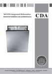
Advanced, 3-Stage
Battery Charger
Stage 2
Absorption
k
!
i.
.
""'d
CHARGING P OFlLE
Automatic Overload Protection
Load Sharing (Select models only)
If you overload your APS, it will automatically protect itself and your valuable batteries from
damage.
Select APS models can be set to limit their own charging functions so they can charge their
batteries at the quickest rate possible without overloading their power input circuits.
Frequency-Controlled Output (Invert Mode)
High Efficiency Output
Your APS controls its output frequency so frequency-sensitive equipment can operate
properly.
Your APS's advanced circuitry produces a more efficient DC-to-AC conversion, minimizing energy
loss. This allows you to run connected equipment longer between battery charges. The APS will
maintain this highly-efficient output even as the battery charge decreases.
Load 'Sense
Your APS conserves battery power by shutting down its inverter when it is not supporting a
load. You can choose at what minimum load your APS will activate its inverter.
Multi-Function Indicator Lights
Several sets of multifunction indicator lights keep you constantly informed of battery charge
levels, fault conditions and APS operation.
Multi-Operation Switches
An array of user-configurable switches gives you convenient options when operating your
APS. You can select the voltage level at which your APS's inverter will turn on to maximize
equipment protection and minimize battery drain; set your APS for maximum charging
efficiency with your battery type; even set up your APS for remote control operation.
Automatic Voltage Regulation (Select models only)
:
Your APS recharges your battery faster
than conventional chargers because
its three-stage charger profile (Bulk,
Absorption and Float) are optimized,
regardless-of-the type of battery you._^^.-use (Wet or Gel).* In addition, the advanced charging system protects
against over-chargeand over-discharge
to ensure a longer service life from
your battery.
* 7he Ahsorprion and Floor levels vary according ro barrer).
rype which is field selecrahlc as eirher "Wer' or "Gel' cell.
Congratulations! You've purchased the most advanced, feature-rich integrated inverter~battery
charger on the market. Your APS provides your equipment with utility-suppliedAC power when it
is available, and during blackouts, overvoltages and brownouts, your APS automatically switches
over to an external battery source to power connected equipment with voltage and frequencycontrolled AC power. In addition to reliable APS performance, your model features:
;
;
4
'VR' APS models regulate incoming AC power, 'boosting' or 'cutting' the voltage to keep your
equipment running through brownouts and overvoltages without draining battery power.
Frequency Controlled Inverter Output
I
I
I
I
I
All APS models feature Frequency Controlled Inverter Output which allows devices dependent
on AC line frequency (such as computers, VCRs, CD players, tape recorders, clocks and
turntables) to operate properly. Your APS is therefore ideal for any of these applications:
computers
microwaves
sump pumps
power tools
and more!
kitchen appliances
refrigerators
electric motors
tape recorders
CD players
VCRs
lights
turntables
CONFIGURATION DIP SWITCH SETTINGS
This manual contains important instructions and warnings that should be followed during the
installation, operation and storage of all Tripp Lite APS Systems.
DIP SWITCH GROUP A (All models1
BA77ERY TYPE/ VOLTAGE POINT
APS Location Warnings
--
Install your APS indoors, away from excess moisture or heat, dust or direct sunlight.
Leave adequate space around all sides of the APS for proper ventilation. The heavier the
load of connected equipment, the more heat will be generated by the APS.
*- Do n o t i t h d P S marmagneticstoragemedia;-asthis mayresult In data wrmpttan~
!
Battery Connection Warnings
You must connect batteries in order for any APS model to operate.
Multiple battery systems must be made up of batteries of the same voltage, age, amp
hour capacity and type.
Keep battery location well ventilated. Explosive hydrogen gas can accumulate near
batteries if they are not kept well ventilated.
Sparks may result during final battery connection.
Do not allow objects to contact the two DC input terminals. Do not short or bridge these
terminals together. Serious injury to property or person could result.
Select-Battery_Type
~.~
~p
(DIP Switch #1, Group A)
~
~~
'
CALITION: The Banery Type DIP Switch sening must march rhe type of banerirs you connecr or your hunerics may he degraded
or damaged over an mended period of rime. See "Barrcry Selecrion." page 7 for more infomarion
..
&itch Posltlon
Gel Cell (Sealed) Battery ............................. UP
Wet Cell (Vented) Battery ........................... Down*
Cell
Select High AC Voltage Switch To Battery Point
(DIP Switch #2. Group
. A)
,
Switch Pos
145V ............................................................. UP
135V ............................................................. Down'
YQ&Q
Do not use Tripp Lite APS Systems in life support applications where a malfunction or
failure of a Tripp Lite APS System could cause failure or significantly alter the performance of a life support device.
Do not connect a surge suppressor, line conditioner or UPS to the output of the APS.
Corded models: Do not remove or modify the ground pin of the APS's plug. Do not use
Weprong adaptors with the APS's plug. Connect your APS only to a properly grounded,
three-wire AC power outlet. Do not plug your APS into itself; this will damage the APS
and void your warranty.
Select Low AC Voltage Switch To Battery Point
(DIP Switches #4, Group A & #3, Group A)
#4 Up & #3
nperation Warnings
Your APS does not require routine maintenance. Do not open your APS for any reason.
There are no user-serviceable parts inside.
Potentially lethal voltages exist within this unit as long as the battery supply is connected.
During any service work, the battery supply and AC input connection (if any) should
therefore be disconnected.
Do not connect or disconnect batteries while the APS is operating from the battery
supply.
-
Batkum~
luipment Connection Warnings
I
Using a small tool, set the 4 'Battery Type I Voltage Point" Configuration DIP Switches, Group A
(located on the front panel of your APS; see Diagram 1, p. 32) to select battery type and set the
voltage range outside of which your APS will switch to battery power.
(
I
own
#4 Down & #3 Up
#4 Down
& #3 Down
Most loads will perform adequately when your APS's High AC Voltage Point DIP Switch #2 is set
to 135V and its Low AC Voltage Point DIP Switches #3 and #4 are set to 95V However. if your APS
frequently switches to battery power due to momentary higMow line voltage swings that would have
little effect on equipment operation, you may wish to adjust these settings. By raising the High AC
Voltage Switch to Battery point and/or loweringthe Low AC Voltage Switch to Battery Point, you may
reduce the number of times your APS switches to battery due to voltage swings.
Factory default wnings.
DIP SWITCH GROUP B (Available on Select Models)
LOAiD SHARING/EQUALIZE BATTERY CHARGE
Usinglasmall tool, setthemLoadSharing'Configuration DIP Switches, #1 and#2of Group B (located
on thc3 front panel of your APS; see Diagram 1, p. 32). DIP Switch #3, Group B should be kept in
the '1JP' position when you are not equalizing your batteries' charges. DIP Switch #4, Group B
has no function.
I Selecting Battery Type I
I
Load Sharing
-- -
(DIP Switches #1, Group B & #2, Group B)
Your APS features a high-output battery charger that can draw a significant amount of power
from your line power source when charging at its maximum rate. If an APS is supplying its full
AC power ratingto its connected load at the same time as it is charging, it could trip its line source
circuit breaker. Trippingthis breaker will cut off AC power to your load and stop batterycharging.
To reduce thechanceof tripping this breaker, select APS models may be set to automatically
limit their charger output to keep the sum of their AC load and charger power within their circuit
breakers' rating.
This charger limiting function has four settings, allowing you to choose less charger limiting
for APS configurations with higher rated breakers. The figures below show how to set your
DIP Switches to select how heavy a load can be placed on your APS before charger limiting
begins.
Even rhough APS models arc high-eficiency converrcrs of elecrriciry, their rared ourpur capaciries arc limircd by rhe amphour size of rhc exrcrnal bancries. ** You musr scr Configurarion DIP Swirch # I . Group A (Bancry Type) ro march rhr r?pe
of barrcries you connecr or your h r r c r i c s may bc degraded or damaged over an cxrcndcd period of rime. See 'APS
Configurarion.' page 5 for more infomarion.)
Selecting~BatteryAmp Hour Capacity
Most Limiting
w a r L
Limiting
Charger limiting begins ar when
rhc APSs load reaches 66% of rhc
APSs load raring. Charger ourpur
falls gradually from f u l l ourpur or
66% of rhc APSk load raring to
abour 40% of full ourpur or full
load.
#1 Down  Up
~-
~
-
-~
- -
p
Stel, 2
:
Divide theTotal Wattage Required (from Step 1) by the battery voltage to determine the DC Amperes
Required.
SkfGk
Charger limiring begins when rhe
APSs load reaches 33% of rhe APSk
load raring. Charger ourpur falls
gradually from f u l l ourpur or 33%
of rhc APSs load raring ro abour
40% of full ourpur or f u l l load
Multiply the DC Amperes Required (from Step 2) by the number of hours you estimate will pass
without AC power before your battery can recharge to determine a Battery Amp-Hours Required
Rough Estimate."
Less Limiting
#1 Up & #2 Down
#1 & #2 Up
-
SteD 1;
Add the Wattage Ratings of your connected equipment to determine the Total Wattage Required.'
Battery Charger Limiting Points
Chargcr limiring rakes cffecr rhe
momcnr any load is applied:
chargcr ourpur f a l l s gradually
from full ourpur ar no load ro no
ourpvl ar full load Thir is rhe f a tory default scrring.
I
Select a battery or system of batteries that will provide your APS with proper DC voltage and an
adequate amp hour capacity: Select 'Deep-Cycle' batteries to enjoy optimum performance from
your APS. Batteries of either Wet-Cell (vented) or Gel-CelVAbsorbedGlass Mat (sealed) construction
are ideal. 6 Volt "golf-cart," Marine Deep-Cycle or 8D Deep-Cycle batteries are also acceptable."
Compensate for inefficiency by multipling your Battery Amp-Hour Required Rough Estimate (from
Step 3) by 1.2 to determine how many amp-hours of battery backup (from one or several batteries)
you should connect to your APS." Note that the Amp-Hour ratings of batteries are usually given
for a 20 hour discharge rate. Actual Amp-Hour capacities are less when batteries are discharged
at faster rates: batteries discharged in 55 minutes provide only about 50% of their listed Amp-Hour
ratings, while batteries discharged in 9 minutes provide as little as 30% of their Amp-Hour ratings.
Thc wanage raring u uually stared in rhc rquipmenr's manuals or on rhrir namcplarcs. If your equipmcnr is rared in
No charger limiring occurs ar any
load size.
ampercs, conven ro warrs by mulriplying rhc ampere raring by your ~ m i n a AC
l line voltage (120). ** Your charging amps
multiplied by rhe charging hours musr crcecd rhc discharge amp-hours rakcn from rhc barrcrics bcwcen charges or you
will evcnrually run down your bancry bank.
No Limiting
#1 & #2 Down'
Equalize Battery Charge
(DIP Switch #3, Group B)
This DIP Switch allows you to equalize the internal resistance of your battery's cells. The
.process is automatic and once started can only be stopped by removing the input power.
I
SElTiNG PROCEDURE:
1) Move to 'Equalize' (DOWN) position for three seconds.
2) Move to 'Reset' (UP) position and leave it there.
Switch P
o1
"iotsi
Reset ............................. ..............................UP'
Equalize ...................................................... Down
Factory defaulr senings.
Reset
Equalize
lnstall two 8 mm (114 in.) fasteners' into a rigid horizontalsurface using the measurements
in the diagram. (Leave the heads of fasteners raised slightly above the horizontal surface in
order to engage the slots in the APS's two front feet.)
Slide APS forward to fully engage the fasteners in the APS's front feet. Install two 8 mm (114
in.) fasteners in the APS's two rearfeet. Tighten the rear screws to permanently hold your APS
in position.
I
CAUTION:Battery charge equalization should only beperformed in strict accordance with
the battery manufacturer's instructions and speciflations.
l%m@amW
(See Diagram 2, p. 32).
Rccommcnded for vehicular insrallarion and orher applicarions requiring pcrmanenr, secure mounring. All
fmencrs arc user-supplied Turn OFF your APS and disconnccr ir complcrcly before mounring.
I
Hardwired Electrical Connections
(All hardwire models)
1. Connect your APS's positive DC Terminal directly to a fuse.
UL recommends that you install a recognized UL component fuse block and fuse within 18
inches of the battery. The fuse's rating must equal or exceed the minimum fuse rating listed
in your APS model's specifications on pages 14 or 15.
2 Choose a battery configuration appropriate to your batteries.
Single Battery Connection: Refer to Diagram 4, page 33. When using a single battery, its
voltage must be equal to the voltage of your APS's lnverter Nominal lnput Voltage (see specs.)
Parallel Battery Connection: Refer to Diagram 5, page 33. When using multiple batteries in
parallel, each battery's voltage must be equal to the voltage of your APS's Inverter Nominal
lnput Voltage (see specs.)
Series Battery Connection: Refer to Diagram 6, page 33. When using multiple batteries in
series, all batteries must be equal in voltage and amp hour capacity, and the sum of their
voltages must be equal tothe voltage of your APS's lnverter Nominallnput Voltage (see specs.)
"
Use the SHORTEST and HEAVIEST GAUGE battery cabling.
Use #4 cabling for DC cable lengths up to 10 feet. Use #2 cabling for lengths up to 16 ft. Shorter
and heavier gauge cabling limits DC voltage drop and allows for maximum transfer of current.'
'APS models ore ropublc of delivering a much higher worruge ourpur for brief periods o j rime. Wiring should be
configured ro W
c rhis brief high-currcnr druw. Though your APS is u high-eficiency conveners of elecrriciry, irs
mted owpw copmiry u limircd by rhc length ond gauge of rhc wires m ' n g from rhc boncry ro rhc APS.
Refer to the electrical schematic. Diagram 3 on page 32, for proper electrical connection of hardwired
APS models. Consult a qualified electrician and follow all applicable electricalcodes and requirements.
1) Loosen screws and remove cover plate from your APS's HardwireAC electrical box. Remove
the knockout covers closest to the desired electrical source and to your equipment.
2) Thread your wires through strain reliefs and through the knockouts.
3) Connect both input and output ground wires to the ground (green) terminal.
4) Connect the incoming hot wire to the input hot (brown) terminal.
5) Connect the incoming neutral wire to the input neutral (blue) terminal.
6) Connect the outgoing hot wire to the output hot (black) terminal.
7) Connect the outgoing neutral wire to the output neutral (white) terminal.
8) Tighten and affix strain reliefs. Replace cover plate and tighten screws.
AC lnput Electrical Connection
(All corded models)
Plug the line cord into an outlet providing 120V AC, 60 Hz. power. Make sure that the circuit you
connect your APS to has adequate overload protection, such as a circuit breaker or a fuse.
'., APS systems may permanently mounted in a car, truck or boat and connected to draw power
from the vehicle's battery. Note: do not connect a 24V or 36V APS to a vehicle's battery. There
are two main ways to make this sort of vehicular battery connection. Choose the Basic Connection
if you are running light hand tools or other small appliances for a brief period of time (seeDiagram
7, p. 34). Choose the Advanced Connection if you are using your APS to power heavy loads for
extended periods of time (see Diagram 8, p. 34). The Advanced Connection incorporates a batteq
isolator and separate battery system to provide battery power to your APS while preventing it from
draining your vehicle's battery. Note: Depending on your application, you may require more than
12V Deep Cycle Battery.
h:N s w o p d pur APS fmm an &mator wichoul a b a i f q connecrcd as shown in Diu#mx 7 or 8, p. 34
AC Output Electrical Connection
(All corded models)
Simply plug your equipment into the unit's AC receptacles.
Set Operating Mode Switch
1
Switch to 'AUTOIREMOTE" when you are using connected equipment. ADVANTAGE:
Provides battery backup power during blackouts or brownouts.
Note: When the swltch is in the "AUTOIREMOTE' position, you can operate a usersupplied swltch to transfer between battery-backup and chargeonly modes. (See
Remote Connector description on page 10.)
Pzfore AC connection, match the power requirements of your
equipment with the power output of your APS to avoid overload.
When figuring the power requirements of your equipment, do not confuse 'continuous' power
ratings with 'peak' power ratings. Electric motors require more power to turn on ('peak power')
than they require to wn continuously. 'Peak' power ratings are usually 2 to 5 times 'Continuous'
ratings. Most electric motors require 'peak power' only when they are turned on. The elecbic motors
in equipment such as refrigerators and sump pumps, however. constantly turn on and off according
to demand. These motors require 'peak power' at multiple, unpredictable times during their operation.
8
Switch to "CHARGE ONLY" when you are not using connected equipment.
(WARNING! APS will not provide battery backup!) ADVANTAGES: A) Continuesto charge battery
when power is present, and 8) Turns OFF the APSs inverter, preventing battery drain during
blackouts or brownouts.
Switch to "OFF to completely turn off the APS and connected equipment or to reset the APS
after it has shut down due to overload or oveheating.