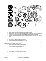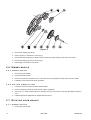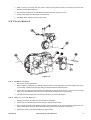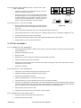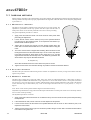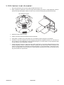
1
MAC 500
s er vi ce m anu al
© 1997, 1998 Martin Professional A/S, Denmark.
All rights reserved. No part of this manual may be
reproduced, in any form or by any means, without
permission in writing from Martin Professional A/S,
Denmark.
Printed in Denmark.
P/N 511000 Revision #980803-MA
section 1
I NTRODUCTION
A BOUT THIS MANUAL ..................................................................................................... 2
S AFETY WARNINGS ....................................................................................................... 2
A DDITIONAL CAUTIONS .................................................................................................. 3
S ERVICE MATERIALS AVAILABLE FROM M ARTIN ................................................................. 3
section 2
P ARTS R EMOVAL AND I NSTALLATION
L OCTITE THREAD LOCK ................................................................................................. 4
R EPLACING T APTITES ................................................................................................... 4
S EPARATING MAIN ASSEMBLIES ...................................................................................... 4
C OLOR WHEEL MODULE ................................................................................................. 6
G OBO ( AND IRIS / FOCUS / PRISM ) MODULE .......................................................................... 6
D IMMER MODULE .......................................................................................................... 8
R OTATING PRISM MODULE ............................................................................................. 8
F OCUS MODULE ........................................................................................................... 9
T ILT MODULES ........................................................................................................... 10
M AIN CIRCUIT BOARD .................................................................................................. 10
P AN ASSEMBLY .......................................................................................................... 11
B ALLAST / TRANSFORMER ASSEMBLY ( MAGNETIC BALLAST MODELS ) .................................... 12
B ASE COOLING FAN .................................................................................................... 12
C ONTROL MODULE ...................................................................................................... 13
section 3
A DJUSTMENT
I NDEXING METHODS .................................................................................................... 14
R OTATING - GOBO WHEEL ( MECHANICAL INDEX ) ............................................................... 15
F IXED - GOBO WHEEL ( MAGNETIC INDEX ) ......................................................................... 15
C OLOR WHEELS ( MAGNETIC INDEX ) ............................................................................... 15
S HUTTER / DIMMER ( MECHANICAL INDEX ) ........................................................................ 16
P RISM ( MECHANICAL INDEX ) ........................................................................................ 16
P AN SENSOR ............................................................................................................. 16
P AN ( ELECTRICAL INDEX ) ............................................................................................ 16
P AN MOTOR SYNCHRONIZATION .................................................................................... 16
T ILT MOTOR SYNCHRONIZATION .................................................................................... 16
O PTIMIZING L AMP A LIGNMENT ...................................................................................... 17
section 4
T ROUBLESHOOTING
G ENERAL .................................................................................................................. 18
S OFTWARE UPLOAD .................................................................................................... 18
M OTORS ................................................................................................................... 18
L AMP ........................................................................................................................ 18
C OLOR WHEELS ......................................................................................................... 19
G OBOS ..................................................................................................................... 20
I RIS , FOCUS , AND PRISM ............................................................................................. 20
S HUTTER / DIMMER ....................................................................................................... 20
P AN / TILT ................................................................................................................... 21
section 5
S OFTWARE L OG
.............................................................................................................................. 22
section 6
M AJOR H ARDWARE C HANGES
.............................................................................................................................. 24
section 7
T YPICAL S PARE P ARTS
911360-000000 MAC 500
IN CARDBOARD ;
230V,50H Z ; ; MSR 575 ; B LACK .................. 26
section 8
B LOCK D IAGRAM
............................................................................................................................. 29
03-08-1998
MAC 500
1
section 1
I N T RO D U C TI O N
1.1 ABOUT THIS MANUAL
1.1.1 PURPOSE
Since its introduction at PLASA in the fall of 1997, the MAC 500 has proven to be an extremely reliable luminaire. Thorough
attention to detail has resulted in a robotic light that is both compact and portable, and yet able to withstand the thumps and
bumps of touring.
Under the extreme conditions of heat and light, components do, however, occasionally wear out or require adjustment. This
manual is a guide to the most common service requirements. It is not intended as an exhaustive reference on how to troubleshoot and replace every single part.
1.1.2 DISTRIBUTION
The MAC 500 Service Manual is available free of charge from the Martin Professional web site at http://www.martin.dk.
1.1.3 ADDITIONAL
SERVICE RESOURCES
• The user manual contains basic troubleshooting, maintenance, and service information.
• The Martin Professional web site at http://www.martin.dk provides a library of information including the user manual, the
latest software updates, control protocols and more.
• A global network of qualified Martin technicians is available to provide service and parts and to answer your technical questions. A list of distributors is maintained on the Martin Professional web site.
• Technical assistance is also available 24 hours a day from the Martin Service Hotline. The number is +45 70 200 201. In the
United States call 1-888-TECH-180.
1.2 SAFETY WARNINGS
Read the warnings and cautions below before servicing the fixture. Some adjustment procedures require that the case and/or
shell is removed while the MAC 500 is under power and the lamp is lit. They shall only be performed by qualified technicians
who are aware of, and can protect themselves from, the hazards involved in working with live circuits and discharge lamps.
IF YOU ARE NOT SURE OF HOW TO PROTECT YOURSELF FROM ELECTRIC SHOCK
AND UV RADIATION, ALWAYS DISCONNECT THE FIXTURE FROM AC POWER BEFORE
AND WHILE SERVICING OR REFER THE WORK TO A QUALIFIED TECHNICIAN.
1.2.1 RISK
OF ELECTRICAL SHOCK
Removal of any cover exposes connectors that carry lethal electric currents. While working on a fixture under power:
• Make sure the fixture is electrically grounded.
• Use a supply with ground-fault-interrupt protection.
• Keep one hand in your pocket.
• Never touch any connector that carries voltage.
• Be careful with tools that conduct electricity.
1.2.2 RISK
OF
UV
RADIATION AND LAMP EXPLOSION
Discharge lamps emit harmful ultraviolet (UV) light which can cause eye and skin burns. In addition, they work under high
temperature and pressure: lamps can and do explode. The explosion risk increases as the lamp ages and the quartz envelope
weakens. To reduce the risk of injury while working on a fixture with the cover removed:
• Never operate the lamp outside the reflector unit.
• Protect eyes with UV-blocking safety goggles. Do not look directly into the light.
• Protect exposed skin with a high factor sun-block.
2
MAC 500
1998-08-03
1.3 ADDITIONAL CAUTIONS
1.3.1 ELECTROSTATIC
DISCHARGE
(ESD)
SENSITIVE PARTS
The following parts are classified as ESD sensitive:
• Motherboard PCB and the individual ICs.
• Keyboard/display PCB and the individual ICs.
• Hall-sensors.
To avoid damaging ESD sensitive parts:
• Ensure that you and your tools have the same potential (ground) as the fixture before and when handling any of the above
components.
• Always store PCBs in antistatic (electrically conducting) bags and store ICs in antistatic foam.
• Always power off the fixture, and allow capacitors do discharge before removing or inserting any components on the PCBs.
1.3.2 INDUCTIVE
LOADS
Always power off the MAC 500 before connecting or disconnecting any of the step motors. Otherwise, damage to the motor
drivers may occur.
1 . 4 S E R V I C E M A T E R I A L S A VA I L A B L E F RO M M A R T I N
1.4.1 PROTECTION
•
•
•
•
•
•
•
•
DEVICES
UV protection glasses, clear .....................................................................................................402010
ESD table mat, 750 x 610 mm...................................................................................................402020
Snap button connector, female, type 4730, for ESD table mat....................................................402022
ESD ground (earth) wire w/2 banana sockets, 4710 ..................................................................402023
Adjustable ESD wrist band........................................................................................................402024
Spiral wire for ESD wrist band...................................................................................................402025
Antistatic bag, 200 x 300 mm ....................................................................................................453801
Antistatic bag, 100 x 125 mm ....................................................................................................453802
1 . 4 . 2 TO O L S
•
•
•
•
•
2 mm T-shaft allen key ..............................................................................................................402001
ESD IC pin straightener combi ..................................................................................................402030
Light duty maintenance tool for AMP MTA 100 sockets ..............................................................402011
Heavy duty pistol grip for AMP MTA 100 sockets (requires head, below) ....................................402012
Heavy duty termination head for AMP MTA 100 sockets (requires grip, above)...........................402013
1.4.3 LUBRICANTS
•
•
•
High temperature synthetic oil, 0.5 liter .....................................................................................400003
Silicone lubricant, 0.5 liter.........................................................................................................400119
Silicone lubricant, 0.2 liter in dispenser with closable valve .......................................................400118
1.4.4 ADHESIVES
•
•
•
1998-08-03
High temperature (300 - 375° C) silicone glue, red ....................................................................400002
Loctite 243 thread lock, 10 ml ...................................................................................................400531
Loctite 290 thread lock, 10 ml ...................................................................................................400533
Introduction
3
section 2
PAR TS REMOVAL AND INSTALLATION
2 . 1 L O C T I T E T H R E A D L O CK
2.1.1 EXTENT
OF APPLICATION
Loctite thread lock is used on all machine screws (this does not include self-tapping or sheet metal screws) to lessen the problems due to the loosening of screws under transport and with time. The thread lock must be reapplied if the screws are loosened
or removed for service.
Two types of Loctite are in use, and are available from Martin Professional. Set screws securing wheels to motor shafts are
secured with the lighter, green, Loctite 290 (P/N 400533). All other screws are treated with the heavier, blue, Loctite 243 (P/N
400531). Both are available in 10 ml tubes.
2.1.2 METHOD
OF APPLICATION
Be careful to avoid getting any material on shafts or axles. A needle and syringe makes an idea application tool.
Long set screws: Start the screw and turn it until it contacts the shaft. Back the screw 2 turns, apply a small drop or 2 of Loctite
290 to the threads, and then tighten the screw as you normally would.
Short set screws: Back the set screw out of the adaptor until 2 threads stick out of the shaft. Apply a small drop or 2 of Loctite
290 to the threads, and then tighten the screw within 60 minutes.
Other metric screws: Apply a drop of Loctite 243 (blue) to 3 or 4 threads, or spread a thin stripe with a syringe, before starting
the screw.
2 . 2 R E P L A C I N G TA P T I T E S
Taptites are not fully round and thus do not have the same strength as regular metric hardware. They are selected, after careful
consideration by R&D, for their excellent thread-cutting abilities.
Taptites shall not be reused in critical locations. Problems can be avoided with the following practice:
Change to metric hardware of the same size when reinstalling used parts originally held with taptites. For the pan/tilt motors,
use M5 x 16 mm allen head bolts, P/N 360855.
Use new taptites when installing new parts. Do not use old taptites to cut new threads! For pan/tilt motors use M5 x 12 mm taptites, P/N 361800.
If the threads in the motors are stripped, use a smaller screw (M4) and a lock nut.
2.3 SEPARATING MAIN ASSEMBLIES
2.3.1 REMOVE
HEAD FROM YOKE
1.
Remove color and gobo modules. Refer to sections 2.4 and 2.6.
2.
Disconnect wires from starter.
3.
Cut the ties holding wires to the chassis; pull the wires out through the tilt bearings on both sides.
4.
Remove the screws holding the head to the tilt bearings and remove the head. These screws are locked with
Loctite and may be difficult to remove - use a screwdriver in good condition.
5.
Installation is the reverse of the above.
2.3.2 REMOVE
1.
YOKE FROM BASE
Remove the plastic covers from both arms.
2. Disconnect the lamp wires from the connection block.
4
3.
Clip the tie holding the lamp wires to the wire bundle leading into the head.
4.
Unplug all wires leading into the base from both sides of the yoke.
5.
Remove the tilt-reset switch wires and cut the tie binding them to the wires leading into the head.
MAC 500
1998-08-03
Figure 2-1
6.
Remove the tilt-sensor circuit board.
7.
Remove the bottom row of 5 screws from both sides of the yoke base and lift off the yoke.
2.3.3 INSTALL
YOKE ON BASE
1.
Set the base on a work table with the circuit-board side facing you.
2.
Turn the yoke base fully clockwise to the mechanical stop; then turn it back 270° counter-clockwise.
3.
Arrange the wires. Lay the bundle with the sensor, fan, rotating-gobo, gobo wheel 1, color wheel 2, dimmer, and
tilt motor and reset switch wires to the left (as the fixture faces you). Lay the bundle with the focus, iris, prism,
rotating prism, color wheel 1, and gobo wheel 2 along with the bundle of 3 lamp wires (black, blue, and yellow/
green) to the right.
4.
Tie the wire bundles to the base using the pair of holes on each end. The wires can be damaged by the shaft
collar if they are tied too tightly. They are too tight if, with power off, there is increased resistance or a slight
spring action at the extremes of the pan range.
5.
Find the side of the yoke with the plastic lamp wire connection block. Place the yoke on the base with the connection block on the right side. Install the 10 screws that hold the yoke to the base.
6.
Connect all wires on both sides of the yoke. When connecting the tilt reset switch wires, it makes no difference
which wire is on top. Replace the tilt-sensor circuit board under the tilt motor.
7.
Tie the wire bundles together where they pass the tilt motors. Do not tie them to the arm. Replace the plastic
arm covers.
1998-08-03
Parts Removal and Installation
5
2.4 COLOR WHEEL MODULE
2.4.1 REMOVE
MODULE
1.
Refer to figure Figure 2-1. Working from the top of the head, remove the top air flow plate (A) and Hall sensor
module (B). There is no need to cut the tie holding the wires to the Hall sensor module.
2.
Unplug the motor wires. Unscrew 2 screws from the bottom of the chassis first and then the screw on the top of
the module.
3.
Clip the tie attaching the prism and focus motor cables to the color module and carefully lift it out.
4.
Installation is the reverse of the above procedure. Make sure the ground wire is connected to the chassis after
installing the module.
2.4.2 REMOVE
COLOR WHEELS
1.
Remove the color wheel module.
2.
Loosen the adaptor set screws and remove the color wheels.
2.4.3 INSTALL
COLOR WHEELS
1.
Remove scratches in the motor axles with a fine file or sandpaper.
2.
Refer to Figure 2-1. First install color wheel 2 (C) as shown. Color wheel 2 has 4 CTC filters and its adaptor is
on the side as the color filters. Position the face of the wheel 2 mm from the face of the motor and tighten a set
screw slightly to fix the position along the shaft.
3.
Install color wheel 1 (D) on the other motor as shown. The adaptor on color wheel 1 is on the opposite side as
the color filters. Position the face of the adaptor 2 mm from the face of the motor and tighten a set screw slightly
to fix the position along the shaft.
4.
Check that the inside wheel turns freely.
5.
Replace the color wheel module and adjust the wheels as described in section3.4.
2 . 5 G O B O ( A N D I R I S / FO C U S / P R I S M ) M O D U L E
2.5.1 REMOVE
1.
Refer to Figure 2-1. Working from the top of the head, remove the top air flow plate (A) and Hall sensor module
(B). There is no need to cut the tie holding the wires to the Hall sensor module.
2.
Remove the bottom air flow plate and unplug the bottom Hall sensor. Unplug all motors on the module.
3.
The gobo module is secured to the bottom of the chassis with 2 screws. Hold it as you remove the screw. Carefully lift out the module and place it upside down on the work table.
4.
Installation is the reverse of the above procedure. When plugging in the bottom Hall sensor, the side of the plug
where the wires attach faces down, towards the circuit board.
2.5.2 REMOVE
ROTATING-GOBO WHEEL
1.
Remove the gobo module.
2.
Refer to Figure 2-2. Unscrew the 3 screws (I) and remove the wheel (J).
2.5.3 INSTALL
ROTATING-GOBO WHEEL
1.
Turn the gobo wheel adaptor (G) clockwise until it stops.
2.
Place the wheel (J) over the adaptor as shown with the open position centered in the light path.
3.
Align the holes and screw in the 3 screws (I).
4.
The rotating-gobo wheel does not normally require adjustment after replacement.
2.5.4 REMOVE
1.
6
MODULE
FIXED-GOBO WHEEL
Remove the rotating-gobo wheel.
MAC 500
1998-08-03
1
2
3
4
5
Figure 2-2
2.
Loosen the 2 set screws on the adaptor (H) and pull off the wheel.
2.5.5 INSTALL
FIXED-GOBO WHEEL
1.
Remove scratches and grooves in the motor axle with a fine file or sandpaper.
2.
Place the wheel on the motor shaft with the black side facing the module. Position the inside face of the wheel
10 mm from the face of the motor. Tighten a set screw slightly to hold the position along the shaft.
3.
Reinstall the rotating-gobo wheel. Replace the gobo module and then adjust the fixed gobo wheel. See procedure 3.3.
2.5.6 REMOVE
GOBO-ROTATION GEAR
1.
Refer to Figure 2-3. Remove the rotating-gobo wheel (J).
2.
Loosen the 2 set screws and pull the adaptor (K) off the axle.
3.
Use a gear puller to remove the drive gear (N) and bearing (M). There is no need to remove the locking ring (L).
2.5.7 INSTALL
SILICONE DRIVE GEAR
1.
Remove scratches in the axle with a fine file or sandpaper.
2.
Refer to Figure 2-3. With the locking ring (L) facing the gobo wheel, press the silicone gear (N) and bearing (M)
onto the shaft together, all the way to the gear (P).
3.
Install adaptor (K). The end of the shaft should be flush with the face of the adaptor. Do not tighten the set
screws.
4.
When replace the rotating-gobo wheel, make sure the set screws are accessible between the gobos.
5.
Refer to procedure 3.2 to adjust the rotating-gobo wheel.
2.5.8 REPLACE
ROTATING-GOBO BEARING
If the bearing requires lubrication, use silicone lubricant, available from Martin in 0.5 liter containers as P/N 400119. Clean the
bearing thoroughly before lubricating.
1998-08-03
Parts Removal and Installation
7
Figure 2-3
1.
Remove the rotating-gobo wheel.
2.
Refer to Figure 2-3. Remove the outer ring (T).
3.
Remove the retaining spring (not shown) from the back of the gobo holder (U) and remove the holder.
4.
Remove the bearing (S) from the outer ring (T).
5.
Reassembly is the reverse of the above.
2.6 DIMMER MODULE
2.6.1 REMOVE
MODULE
1.
Remove the gobo module.
2.
Unplug the dimmer motors.
3.
Remove 2 screws from the bottom and 1 screw from the top of the dimmer module and remove the module.
4.
Installation is the reverse of the above procedure.
2.6.2 REPLACE
DIMMER BLADES
1.
Loosen the set screws and remove the dimmer blades.
2.
Remove scratches in the motor axles with a fine file or sandpaper.
3.
See Figure 2-1. Install a dimmer blade on the right motor (as seen from the rear) with the adaptor facing the
front.
4.
Install the left dimmer blade with the adaptor facing the motor.
2.7 ROTATING PRISM MODULE
2.7.1 REMOVE
1.
8
MODULE
Remove the gobo module.
MAC 500
1998-08-03
2.
Refer to Figure 2-4. Through the open gobo in the fixed gobo wheel, remove the 2 screws (A) from the rear.
Remove 2 screws (B) from the top.
3.
Grip the brass coupling nut (H) with pliers and remove the screw (C) from the front.
4.
Lift the prism module over the spacer nut and remove.
5.
Installation is the reverse of the above procedure.
2.8 FOCUS MODULE
Figure 2-4
2.8.1 REMOVE
MODULE
1.
Remove the rotating-gobo wheel.
2.
Refer to Figure 2-4. With tape or a marker, mark the position of the drive belt (not shown) in relation to the front
of the module. Loosen the screws (E) holding the angle bracket and release the belt.
3.
Loosen the set screws (D) securing both focus slide pins (F and G). There is only 1 set screw, in the outside
holes, in the rear adaptors. There are 2 set screws in the front adaptor for the long slide (F).
4.
Carefully drive out the slide pins from back to front with a pin punch and hammer.
2.8.2 INSTALL
FOCUS MODULE
1.
Remove scratches in the slide pins with a fine file or sandpaper.
2.
Position the focus module and insert the slide pins. Tighten the set screws.
3.
Fill a syringe with Martin P/N 400003 synthetic, high-temperature oil. No other lubricant is approved for use.
Apply a few drops of oil to both slides. Be careful not to get oil on the drive belt or other parts.
4.
Replace the rotating-gobo wheel. Replace the gobo module.
1998-08-03
Parts Removal and Installation
9
5.
Thread the focus belt over the back roller, under the motor, and over the front roller. Stretch the belt to the position you marked earlier and secure under the angle bracket. With the focus mechanism all the way to the rear,
the belt should deflect about 3 mm (1/8”) when pressed lightly between the roller and angle bracket. Adjust the
tension if focus movement is choppy.
2.9 TILT MODULES
2.9.1 REMOVE
TILT BELT
1.
Remove the head from the yoke bearing on the side to be serviced. See procedure 2.3.1.
2.
Remove the 6 screws holding the tilt assembly to the arm.
3.
Slide the belt off the large gear.
2.9.2 REPLACE
TILT BELT
1.
Put the belt on the small gear, then the large gear.
2.
Replace the tilt assembly on the yoke.
3.
Locate the mechanical stop bolt on the large gear. Turn the gear until the stop bolt is at the bottom.
4.
Place the head in the yoke with the lens pointing up and the side with the ground connector (E in Figure 2-1) to
the right.
5.
Make sure the holes in the yoke bearing spacer ring align with the holes in the tilt gear and reinstall the head on
the bearing.
2.9.3 REMOVE
TILT MOTOR
1.
Remove tilt belt on side to be serviced. See section 2.9.1.
2.
If removing the motor on the tilt sensor side, remove the sensor bracket.
3.
Loosen the set screws.
4.
Remove the gear from the motor shaft.
5.
Remove the motor.
2.9.4 INSTALL
TILT MOTOR
1.
Install the tilt motor with the wires hanging down, towards the base.
2.
Put the gear on the motor shaft. Do not tighten the set screws.
3.
If installing the motor on the tilt sensor side, install the sensor bracket. Center the timing wheel in the sensor.
4.
Tighten a set screw slightly to fix the gear along the shaft. The gear must be able to rotate on the motor shaft
when it is synchronized with the other motor.
5.
Install the tilt belt.
6.
Synchronize the tilt motors. See procedure 3.10.
2 . 10 M A I N C I R C U I T B O A RD
2.10.1 REMOVE
10
CIRCUIT BOARD
1.
Unplug the connectors from the top of the circuit board.
2.
Lifting by the 2 black pins on the ends, pull the board partially out.
3.
Unplug remaining connectors and remove the board.
MAC 500
1998-08-03
PIN-OUT AND BOOT SET-
1.
Position the jumpers for the desired XLR pin-out on PL
233/234 as shown in Figure 2-5.
2.
Position the jumper on PL 121 for the desired boot setting
as shown in Figure 2-5. The hard boot setting is only used
to upload software when the fixture must be set to boot
mode and the control panel does not function. After the
upload, move the jumper back to the normal setting.
2
-
2
-
+
3
+
3
Martin pin-out
PL121
DMX pin-out
(default)
PL121
1
2.10.3 INSTALL
hard boot setting
CIRCUIT BOARD
INIT
TING JUMPERS
INIT
2.10.2 CONFIGURE XLR
1
normal setting
1.
Before installing a board, make sure the hard boot jumper
and XLR pin-out jumper are configured correctly. See section 2.10.2.
2.
Plug in connectors at the bottom of the card. See the block diagram in section 8.
3.
Plug in the lamp relay wires: mains in (red) to RL 3, ballast in (brown) to RL 4, and ballast out (black) to PL 221.
4.
Tuck lamp relay wires under the motor assembly.
5.
Guide the circuit board into position and lock by snapping the black pins into their holders.
6.
Plug the cables in to the top of the circuit board.
Figure 2-5
2 . 11 P A N A S S E M B L Y
2.11.1 REMOVE
PAN ASSEMBLY
1.
If removing the pan assembly to replace a pan motor, you may find it easier to remove the yoke from the base.
See procedure 2.3.2.
2.
Remove the side profile from back.
3.
Remove AC filter.
4.
Remove the 6 x 10 mm locking nuts holding the pan assembly to the base.
5.
Unplug the 2 wires from the pan reset switch.
6.
Unplug the pan sensor cable under the sensor timing wheel and unplug the pan motor cable from the connection below the sensor module.
7.
Remove the assembly.
2.11.2 INSTALL
PAN ASSEMBLY
1.
Arrange the circuit board and lamp relay wires neatly in the base.
2.
Fasten the transformer wires to the back rail with a wire tie.
3.
Position the pan assembly in the base.
4.
Fasten the assembly with 6 x 10 mm bolts and lock nuts.
5.
Install the AC filter on the pan assembly with the “load” end towards the ballast.
6.
Connect the AC filter wires. On the line side, connect the neutral (blue) wire to the top terminal, the live (brown)
wire to the bottom terminal, and ground wire to the case. Similarly, on the load side, connect the blue wire leading to the capacitor to the top terminal and connect the brown wire to the bottom terminal.
7.
Plug in the pan sensor and motor wires.
8.
Plug the pan-reset switch wires into the bottom 2 switch contacts.
2.11.3 REPLACE
PAN DRIVE BELT
1.
Remove the yoke from the base. See procedure 2.3.2.
2.
Remove the pan sensor module.
1998-08-03
Parts Removal and Installation
11
3.
Slip the old belt off the pan drive gear first, them off the pan motors, and remove.
4.
Guide the new belt over the wires, yoke base, and pan timing wheel.
5.
Position the belt on the small motor gears first, then on the large drive gear.
6.
Replace the pan sensor module. Replace the yoke and head.
2.11.4 REPLACE
PAN MOTORS
1.
Remove the pan assembly.
2.
Remove the pan sensor module.
3.
Remove the pan drive belt: slip it off the large gear first, then off the motor gears.
4.
Loosen the set screws holding the gear to the motor shaft and remove the gear.
5.
Remove the 8 mm hex bolts and remove the motor.
6.
Install the new motor in the pan assembly.
7.
Place the gear on the motor shaft level with the drive gear. Tighten the set screws just enough to hold the vertical position along the shaft.
8.
Replace the assembly in the base.
9.
Install the drive belt.
10. Replace the pan sensor module.
11. Synchronize pan motor step: see procedure 3.9.
2 . 12 B A L L A S T / T R A N S FO R M E R A S S E M B LY ( M A G N E T I C B A L L A S T M O D ELS)
2.12.1 REMOVE
ASSEMBLY
1.
Remove the main circuit board and pan assembly.
2.
Remove the 4 cam locks and the 10 screws from the mounting rails.
3.
Remove both handles.
4.
Cut the tie holding wires to the back rail.
5.
Disconnect the ballast and transformer wires.
6.
Lift out the assembly.
7.
Installation is the reverse of the above procedure. Be sure to align the cam locks with the slots in the base and
mounting rails before tightening.
8.
Connect both black ballast wires to ballast terminal 1. Connect the brown ballast wire according to your frequency and voltage. See user manual.
9.
Connect the both blue transformer wires to transformer terminal 1. Connect the brown and red wires to according to your frequency and voltage. See user manual.
2 . 13 B A S E C O O L I N G F A N
2.13.1 REMOVE
12
FAN
1.
Remove the main circuit board. Remove the handle from the fan end, and remove the 4 screws from the power
input/serial link panel. Remove the screws holding the side profile at the fan end.
2.
Unplug and remove the fan.
3.
Installation is the reverse of the above.
MAC 500
1998-08-03
2 . 14 C O N T RO L M O D U L E
2.14.1 REPLACE
1.
Remove the main circuit board. Remove the 4 nuts from the back of the control panel and remove the control
panel.
2.
Installation is the reverse.
1998-08-03
Parts Removal and Installation
13
section 3
ADJUSTM E NT
3 . 1 I N D EX I N G M E T H O D S
Effects indexing in the MAC 500 is determined by one of three methods. The adjustment procedure for the effect depends on its
indexing method. The lamp must be properly adjusted before the alignment of the other effects can be adequately judged. Refer
to procedure 3.11.
3.1.1 MECHANICAL
INDEXING
The effect is driven against a mechanical stop and comes to rest at a step position. The
adjustment is performed from this step position and thus requires that the motor is
under power. Please review the safety information in section 1 before proceeding.
The general adjustment procedure is as follows.
1.
Apply power and reset the fixture. The motor must be under power while
performing the adjustment.
2.
Loosen the set screws. Set the wheel (or arm) to the specified distance
from the motor or other reference point, or as required for free rotation. Tip:
Drill bits make excellent spacers.
3.
Tighten the set screws just enough to fix the wheel’s position along the
motor shaft. The wheel must be able to turn on the shaft without moving the
motor.
4.
The motor must be where it stopped after resetting. Move the wheel so that
the angle between it and the mechanical stop is 1/3 of a motor step. Motors
in the MAC 500 have 50 whole steps (cycles); each step is 7.2° and the
angle between the effect and the stop is 2.4°. The distance (A) between the
wheel and the stop may be calculated as follows:
A
B
A = B (tan 2.4°)
where B is the distance from the motor shaft to the point of contact.
5.
Tighten the set screws. Run the effect through its positions and then recheck the distance.
3.1.2 ELECTRIC
INDEXING
The MAC 500’s pan and tilt are indexed using electric switches. No adjustment is necessary as long as the switches close during the reset procedure.
3.1.3 MAGNETIC INDEXING
The MAC 500’s rotating gobos, fixed-gobo wheel, and 2 color wheels are indexed magnetically. A Hall sensor IC detects a
miniature magnet mounted on the effect wheel. Proper adjustment is critical. If the wheel or sensor is out of position, the effect
may not reset, or, if it resets, may begin to "wander" when the fixture reaches operating temperature. This is due to the fact that
sensors' detection range is small and they only "look" for the magnet when the motor is at a cycle position, i.e., every 7.2
degrees.
Note: The IC sensor must be parallel with the magnet for maximum sensitivity.
Adjustment is performed from a step position and thus requires that the motor is under power. Please review the safety information in section 1 before proceeding.
The adjustment procedure is as follows.
14
1.
Apply power and reset the fixture but do not strike the lamp. The motor must be under power while performing
the adjustment.
2.
If the wheel fails to reset, wait for it to time-out and adjust from this position.
3.
Loosen the set screws. Set the wheel to the specified distance from the motor or other reference point, or as
required for free rotation.
4.
Tighten the set screws just enough to fix the wheel’s position along the motor shaft. The wheel must be able to
turn without moving the motor.
MAC 500
1998-08-03
5.
Center the effect in the light path. Begin by visually centering the effect with the lamp off. Then strike the lamp
and focus the beam on a flat surface to confirm proper alignment. Adjust if necessary and then tighten both set
screws.
6.
Once the wheel is optically aligned, rotate the effect until the magnet is under the sensor. This can be done by
selecting the wheel from the MAN or ADj menu and setting it to the open position.
7.
To adjust the Hall sensor, position the IC directly over the magnet at a distance of 1 - 1.5 mm and keep it parallel
with the circuit board. Its position can be adjusted by moving or bending the PCB mounting bracket but not by
bending the leads of the IC itself.
3.2 ROTATING-GOBO WHEEL (MECHANICAL INDEX)
1.
With the module installed and the power off, check that the wheel turns freely. If the wheel does not turn freely,
move it in or out until in does.
2.
Loosen both set screws on the adaptor. Tighten one set screw slightly to hold the position along the shaft. The
set screws must be loose enough to allow the wheel to turn along the motor shaft.
3.
Apply power and reset the fixture. From the control panel, select MAN>RGOB. With the gobo wheel in the open
position and the lamp off, look into the front lens and manually center the wheel in the optical path. Partially
tighten the set screw.
4.
If the set screw is not accessible with the wheel in the open position, use the up and down arrow keys to select
a gobo position where you can access a set screw. Center the gobo in the optical path and then partially tighten
the set screw.
5.
Turn on the lamp and focus a gobo to check alignment. Move the wheel back and forth a little by hand to see if
the gobo is centered. When the wheel is aligned, fully tighten both set screws.
3 . 3 F I X E D - G O B O W H E E L ( M A G N E T I C I N D EX )
1.
With power off, check that the wheel turns freely 360°.
2.
Loosen both set screws. If the wheel does not turn freely, move it in or out until in does. Tighten one set screw
slightly to hold the position along the shaft.
3.
Reset the fixture. The fixed gobo wheel may not reset if the wheel is too far out of alignment; the procedure will
time-out and a fixed gobo error will occur. If this happens, loosen the set screw and adjust the wheel from this
motor position.
4.
From the control panel, select MAN/FGOB. With the gobo wheel in the open position and the lamp off, look into
the front lens and manually center the wheel in the optical path. The set screws must be loose enough to allow
the wheel to turn along the motor shaft. If the motor does turn a step, it must be returned to the reset position.
Repeat the reset procedure if necessary.
5.
Tighten the set screw when the open gobo is centered. If the set screw is not accessible with the wheel in the
open position, use the up and down arrow keys to turn the gobo wheel to a point where you can access and
tighten a set screw. Center the gobo in the optical path and tighten the set screw.
6.
Turn on the lamp and visually check alignment. Move the wheel back and forth a little by hand to see if the gobo
is centered. Adjust if necessary. When the wheel is aligned, tighten the second set screw.
7.
To adjust the sensor, rotate the gobo wheel to the open position. Position the sensor directly over the magnet at
a distance of 1 - 1.5 mm. The sensor can be moved by carefully moving the IC itself.
3.4 COLOR WHEELS (MAGN ETIC INDEX)
1.
With power off, check that the color wheels turn freely 360°. Adjust the position along the motor shaft if necessary.
2.
Loosen the set screws. Tighten one screw on each wheel slightly to fix the position along the shaft.
3.
Reset the fixture and strike the lamp. Select MAN>COL2 from the control menu. Use the arrow keys to turn color
wheel 2 to a point where you can access a set screw.
4.
Center the color filter in the light path. The color must be even across the field and there should be no shadows
at the edges.
5.
Tighten the set screw. Return the color wheel to the open position.
1998-08-03
Adjustment
15
6.
Repeat steps 3 and 4 for color wheel 1.
7.
Use the control panel to test alignment at a number of positions. When the wheels are aligned, tighten the second set screw.
8.
To adjust the sensors, rotate the color wheels to the open position. Position the sensors directly over the magnets at a distance of 1 - 1.5 mm. The sensors can be moved by carefully moving the ICs.
3.5 SHUTTER/DIMMER (MECHANICAL INDEX)
1.
Position both dimmer blades with 11 mm between the surface closest to the motor and the dimmer motor
mounting plate. Tighten a set screw slightly to fix the position along the motor shaft.
2.
Reset the fixture.
3.
With power on, position each dimmer blade 0.8 mm from the closed-position mechanical stop and tighten the
set screws.
4.
Check that the dimmer opens and strobes properly. Close the dimmer and check that the distance from the
mechanical stops is still 0.8 mm. Tighten the second set screw on each blade.
3.6 PRISM (MECHANICAL INDEX)
1.
With the power off, slide the focus module all the way forward.
2.
Swing the prism in and out of the optical path. Bend the mechanical stop for the prism flag in slightly if the prism
hits the focus motor.
3 . 7 PA N S E N SO R
No adjustment is required; the timing wheel is centered in the sensor when the pan motor gear is level with the pan drive gear.
3 . 8 PA N ( E L E C TR I C A L IN D EX )
1.
Loosen the 2 screws holding the pan reset switch to the pan assembly.
2.
Turn the yoke fully clockwise.
3.
Move the switch up or down so that the top of the copper spring is even with the top of the mechanical stop bar,
approximately 1 mm below the pan drive gear.
4.
Tighten the bracket mounting screws.
3 . 9 P A N M O T O R S Y N C H RO N I Z A T I O N
1.
With the belt on, loosen one of the motor gears just enough to turn it on the shaft without it moving up or down.
The gear must be able to rotate on the shaft when power is applied to the motors.
2.
Turn on and reset the fixture to apply power to the motors. If the unit is disassembled, you can use the pan
driver from another unit. Remember to turn off the fixtures before connecting or disconnecting the motors.
3.
Tighten the set screws on the loose gear.
3 . 10 T I L T M O T O R S Y N C H RO N I Z A T I O N
16
1.
Loosen one of the motor gears just enough to turn it on the shaft without it moving back or forth. The gear must
be able to rotate on the shaft when power is applied to the motors.
2.
Apply power to the fixture and reset.
3.
Using a controller or the control panel, tilt the head until a set screw is accessible from above.
4.
Tighten the set screw with a 2 mm Allen wrench.
5.
Tilt the head a few degrees until the second set screw is accessible. Tighten.
MAC 500
1998-08-03
3 . 11 O P T I M I Z I N G L A M P A L I G N M E N T
1.
Disconnect the fixture from AC power supply and allow the lamp to cool.
2.
Make a preliminary adjustment: remove the lamp-socket assembly and use the 3 lamp adjustment screws to
position the lamp-socket plate a distance of 38 mm (1.5”) from the access plate (outside measurement).
lamp adjustment screws
3.
Replace the lamp-socket assembly.
4.
Switch on the MAC 500 and wait until the reset has finished.
5.
Using either a controller or the control panel, turn on the lamp and focus the light on a flat surface.
6.
Center the hot-spot (the brightest part of the image) by using the three adjustment screws. Turn one screw at a
time to drag the hot-spot diagonally across the projected image. If you cannot detect a hot-spot, adjust the lamp
until you achieve an even distribution of the light.
7.
If there is too much hot spot or a dark spot in the center of the beam, you can further adjust the lamp by turning
all three adjustment screws a quarter-turn clockwise, making sure that the hot-spot remains centered. If the
result is an improvement then repeat this procedure until there is no more improvement. If the result is worse,
then turn the adjustment screws a quarter-turn counterclockwise and observe the result. Proceed this way as
long as the result is an improvement.
1998-08-03
Adjustment
17
section 4
TROU BL ES HO O TI NG
4.1 GENERAL
4.1.1 FIXTURE
DOES NOT RESET
• Blown fuse: LEDs on the printed circuit board light up to indicate the power supplies are working. Check / replace the fuses
on the circuit board if one or more of the LEDs is not lit.
• Sensor connection reversed: The MAC 500 will not reset properly if any of the Hall sensor connections on color wheel 1 or
2, the fixed-gobo wheel, or gobo indexing is reversed.
4.1.2 FIXTURE
RESETS BUT DOES NOT RESPOND TO THE CONTROLLER
• Memory error (MERR): A memory error occurs randomly in fixtures with S/Ns from approximately 980201-001 to
980731-000 due to a change in the EEPROM used to store user data including mode and address, which the supplier failed to
Martin about. The problem is fixed in software from version 1.6.
• Missing or incorrectly set jumper: The MAC 500 has a jumper on the PCB to configure the pin-out of the XLR jacks. The
default configuration is DMX pin-out, i.e., pin-2 (-) and pin-3 (+). The fixture will not respond to DMX if the jumper is missing or set to Martin protocol. Refer to section 2.10.2.
• Bad connection: Check the connection at PL231. Check the continuity from the XLR input to the motherboard.
• Failure in the link: Diagnosing link problems is beyond the scope of this manual. See Recommended Practice for DMX512,
A Guide for Users and Installers, by Adam Bennette, available from PLASA, Ltd. and USITT Inc.
4.2 SOFTWARE UPLOAD
4.2.1 FIXTURE
DOES NOT ACCEPT NEW SOFTWARE
• Corrupted software: The fixture will not respond to the MPBB1 uploader if its software is corrupted. It can be forced into
upload mode by setting it to boot mode from the control panel or, if that does not work, by moving the jumper on the motherboard at PL 121 to the “INIT” position. See also the software log and procedure 2.10.2.
4.3 MOTORS
4.3.1 STEP
MOTOR DOES NOT TURN, OR TURNS ERRATICALLY
To avoid damage to the step drivers, always turn off the power before connecting or disconnecting the motors.
• Burned-out step driver: Most step motor problems are due to a burned-out driver. A burned-out driver results in erratic or
no movement. Test the driver with the Martin step drive tester or switch the motor to another circuit.
• Bad connection: Check continuity between the motor and the PCB. Alternatively, check the connections from the PCB to
the connection block by putting a working motor on the circuit. Check the wires from the motor by plugging it into a working
circuit.
• Burned out motor: You should only feel slight resistance when turning a step motor by hand. Replace the motor if it is hard
to turn. You can also check for equal resistance on the windings.
4.3.2 MOTOR
TURNS THE WRONG DIRECTION
• Reversed motor cable: Unplug the motor cable and flip it over.
4.4 LAMP
4.4.1 LAMP
DOES NOT STRIKE
The main reasons for lamp failure are a blown lamp, a hot lamp, and incorrect power settings. Discharge lamps become harder
to strike with use - an incorrect power setting may not be immediately apparent. Check the settings, allow the lamp to cool, and/
or try another lamp. Make sure the lamp is securely held in the socket. If this does not help, the problem may be one of the following.
• No power to the lamp (faulty relay): Turn the lamp on from the control panel. If you can hear the lamp relay “click”, the
control circuit is working. With the head in neutral position, remove the plastic arm cover on your right and, after switching
18
MAC 500
1998-08-03
the lamp circuit on, measure the voltage across the heavy blue and black wires at the connection block. The reading should be
the same as the AC line voltage when the lamp is off. If there is no voltage, but the relay “clicks,” the relay contacts are
defective.
• Defective phase compensation capacitor: A bad phase compensation capacitor (the large capacitor located next to the ballast) may cause the main fuse to blow when striking the lamp.
• Defective ballast: Test the fixture with another ballast before replacing.
• Defective starter: Do not attempt to measure the starter voltage. The high starter voltage is dangerous and can damage your
meter. Replace the starter if the lamp still does not strike after eliminating the above causes.
4.4.2 SHORT
LAMP LIFE
• Incorrect power setting: Lamp life will be shortened considerably if the ballast setting is incorrect and the voltage is too
high. Refer to the user manual for proper setting information.
• Contaminated lamp: Oils from your fingers or other sources will weaken the glass envelope.
• Defective ballast: A defective ballast can provide too much power to the lamp and result in shorter lamp life.
4.4.3 LAMP
CUTS OUT/FIXTURE OVERHEATING
• Incorrect power setting: See the user manual for proper setting information.
• Dust and dirt reducing air flow: Clean the fixture.
• Bad fan or connection: Both fans in the head must be operating to provide adequate cooling. Check that the fans are connected and working.
• Defective thermo-switch: The thermo-switch cuts power to the lamp if the fixture overheats. A faulty thermo-switch may
cause the lamp to cut out at too low a temperature. Never bypass the thermo-switch!
4.5 COLOR WHEELS
4.5.1 COLOR
WHEELS LOSE STEP
• Acceleration curves in software versions before 1.2 occasionally caused the color wheels to lose step. Install software version
1.2 or higher.
• Software bug: Versions 1.2 and earlier had a bug that resulted step loss on the color and rotating gobo wheels during rapid
updates from certain desks, notably the Strand Genius 520/530.
4.5.2 COLOR
WHEELS START ROTATING SPONTANEOUSLY
• Improper adjustment: This can occur when the fixture reaches operating temperature if there is too much distance between
the wheel’s magnet and the sensor IC. When the wheels are properly aligned and in the open position, the sensor must be parallel with the magnet and directly over it at a distance of no more than 1.5 mm (1/16 in). Make sure the wheel is properly
aligned before attempting to adjust the sensor position. See procedure 3.4.
4.5.3 COLOR
WHEEL TIME OUT
( C1ER, C2ER)
• Improper optical alignment: The sensor may not be able to detect the indexing magnet if the wheel is out of alignment.
Refer to the color wheel adjustment procedure.
• Improper sensor alignment: If the color wheel fails to reset when it is properly aligned, the sensor IC may be too far from
the indexing magnet. The maximum distance between the sensor and the magnet is 1.5 mm.
4.5.4 COLOR
WHEELS STOP AT THE WRONG POSITION
• A bug in software versions before 1.2 occasionally caused color wheel 2 to reset incorrectly. Upgrade to version 1.2 or
higher.
4.5.5 COLOR
WHEELS MOVE SLOWLY
• A bug in software versions 1.3 and before caused an incorrect color and/or an unintended fade time on the color wheels in
tracking mode when bumping from a fixed color value (DMX 145 - 184) to a color scroll value (DMX 0 - 144). This problem
may be worked around by programming colors from within the "color scroll values", i.e., 0 for white, 16 for color 1, 32 for
color 2, 48 for color 3 and so on, instead of using the values between 145 and 184. All colors can still be achieved. Another
option is to program a fade time on the color speed channel if using modes 3 or 4.
1998-08-03
Troubleshooting
19
4.6 GOBOS
4.6.1 FIXED-GOBO
WHEEL STARTS ROTATING SPONTANEOUSLY
• Improper adjustment: This can occur when the fixture reaches operating temperature if there is too much distance between
the wheel’s magnet and the sensor IC. When the wheel is properly aligned and in the open position, the sensor must be parallel to the magnet and directly over it at a distance of no more than 1.5 mm. Make sure the wheel is properly aligned before
attempting to adjust the sensor position. Refer to procedure 3.3.
4.6.2 GOBO
WHEEL TIME OUT
( FgER, RgER)
• Improper optical alignment: The sensor may not be able to detect the indexing magnet if the wheel is out of alignment.
Refer to the gobo wheel adjustment procedures.
• Improper sensor alignment: If the fixed-gobo wheel fails to reset when properly aligned, or if the rotating-gobo indexing
fails, the sensor IC may be too far from the indexing magnet. The maximum distance between the sensor and the magnet is
1.5 mm.
4.6.3
ROUGH OR NOISY GOBO SELECTION
• Belt too tight: Adjust tension by removing the rotating-gobo wheel from the shaft adaptor (see Figure 2-2) and adjusting the
4 motor-mounting screws to tilt the motor shaft closer to, or further away from, the silicone drive gear.
• Loose wheel: A noisy wheel probably indicates that the rivets or screws connecting the wheel to the shaft adaptor are loose.
On the fixed-gobo wheel, replace the rivets (3.2 x 8 mm, P/N 376478). For extra strength, the wheel may be glued to the shaft
adaptor with red, high-temperature silicone adhesive.
4.6.4 ROUGH
GOBO ROTATION
• Gobo bearings not seated correctly: If the bearing is not pressed all the way into its holder (the black plastic part that
screws to the wheel), the gobo holder rubs against the bearing holder, increasing friction and making noise or causing jerky
rotation. The problem is fixed by pressing on the gobo holder from the lamp side until the bearing snaps into the proper position. The proper clearance between the gobo holder and the bearing holder is approximately 0.5 mm.
• Worn, dirty, or dry bearing: Clean and lubricate the bearing with silicone lubricant. See procedure 2.5.8. Replace the bearing if necessary.
4.6.5 GOBOS
SLIP IN HOLDER
• Gobo and/or retaining spring not seated correctly: The gobo and spring must be squarely seated flush against the gobo
holder. Use a small flat-tip screwdriver to position the gobo and spring. For extra security, the gobo may be glued in place
with 3 drops of red, high-temperature silicone adhesive.
4 . 7 I R I S , FO C U S , A N D P R I S M
4.7.1 NOISY
IRIS
• Iris noise at fast speed is can be caused by vibrations from the drive motor. Operating the iris at slower speeds reduces the
noise. Replacing the iris is the only other solution. We are investigating ways to reduce iris noise.
4.7.2 VISIBLE
IRIS GRAPHITE
• Excess graphite powder can accumulate at the edge of the iris blades and become visible in the projected image. This excess
may be removed by blowing it away. Be careful though not to get the powder on lenses and other optical parts.
4.7.3 ROUGH
FOCUS
• Improper belt tension. If the focus drive belt is too tight or too loose, focus action will be choppy or difficult. Refer to
“Install focus module” on page 9.
• Focus slides need lubrication. Refer to section 2.8.2.
4.8 SHUTTER/DIMMER
4.8.1 RANDOM
SHUTTER ACTION
• A bug in versions 1.3 and before causes the DMX signal on a random channel to be misinterpreted for a fraction of a second,
after which normal control returns. This is only seen with certain controllers, for example the Strand 520, and can affect any
20
MAC 500
1998-08-03
effect but is most visible when it affects the shutter. Install version 1.4.
4.8.2 SHUTTER/DIMMER
LOSES STEP, CAUSING LIGHT LEAKAGE WHEN CLOSED
• Shutter/dimmer acceleration in software versions before 1.2 occasionally caused the shutter/dimmer to lose step with some
control desks. Install software version 1.2 or higher.
4.8.3 DIMMER
RESPONDS SLOWLY WHEN BUMPED
• A bug occasionally caused the dimmer to react slowly. Install version 1.2 or higher.
4 . 9 PA N / T I L T
4.9.1 PAN
OR TILT FAILS TO RESET
( PAER, TIER)
• Defective indexing switch: The reset fails if the pan and/or tilt reset switches fail to close. Check the connections. Close the
switch manually and check for continuity across the contacts.
• Improper pan reset switch adjustment: Refer to section 3.8.
4.9.2 FEEDBACK
ERROR
( FbER, FbEP, FbET)
• Dirty optical sensor: The pan and tilt position sensors are optical and must not be obstructed by dust or dirt. Clean the sensor with compressed air.
4.9.3 HEAD
STICKS IN YOKE
• The head may get stuck if the shells are not seated correctly, thereby forcing the rubber joint against the yoke. Remove the
shell and replace it correctly.
4.9.4 PAN
A N D T I L T N O I S Y, S L O W , O R L O S I N G S T E P
• Fixture out of balance. See “Balance plates” on page 24.
• Outdated software: Pan/tilt motor control in software up to version 1.4 does not take into account the added inertia due to
the achromatic lenses and counterbalance plates: step loss can occur at maximum speed if pan/tilt speed (PTSP) is set to fast.
• Motors out of phase. Adjust pan or tilt motors. Refer to “Pan motor synchronization” on page 16 or “Tilt motor synchronization” on page 16.
• Different personality setting. Check that all fixtures have the same pan/tilt speed setting (fast/norm). Refer to the user manual.
• Bad connection. If there is a bad connection to one of the drive motors, speed will be reduced because only one motor is
working. Check that all wires are securely crimped in the connector. To avoid damaging the step drivers, always turn off the
power before connecting or disconnecting motors.
• Loose drive gear. To check and tighten the drive gears, refer to the procedures for pan and tilt belt replacement.
• Bad motor. Pan and tilt may continue to work even if one of the motors is defective.
1998-08-03
Troubleshooting
21
section 5
SO FT WA RE LO G
Version
& Date
1.6
Changes
•
"MERR" problem solved. Some fixtures were subject to a periodic "MERR" (memory error) due to a change in specifications to an EEPROM (IC103), which our supplier did not notify us about. This meant that all settings were corrupted, including DMX address and protocol. This version solves the problem.
•
•
Pan and tilt bump response for small movements improved in DMX tracking mode.
Lamp check implemented. If the lamp explodes, lamp feedback disappear and pan/tilt are disabled to prevent hot
glass fragments from being flung from the fixture.
Maximum pan/tilt speed in FAST mode reduced to eliminate step-loss due to the heavier achromatic lenses.
Lamp strike delay implemented. Necessary when using the electronic ballast version. If the lamp has been switched
off, the lamp can not be struck again for an 8 minute period. If a lamp-on command is received, the fixture will store
the command, display a "HOT" message and then automatically strike the lamp when the 8 minutes are up.
Bug fix: Bump from fixed color values (145 - 184) to color scroll values (0 - 144) in DMX tracking mode could cause
slow movement on both color wheels.
Bug fix: The fixed-gobo wheel would sometimes be offset after resetting. The offset would, though, be corrected
while operating by the on-the-fly position correction system.
Bug fix: The DMX signal on a random channel could be misinterpreted for a fraction of a second, resulting in unpredictable behavior for a brief instant, after which normal control returned. This was most noticeable when it affected
the shutter, as it reacts the fastest. The problem occured at an interval of several minutes and only with certain DMX
desks, for example, the Compulite Animator.
Boot-sector bug fixed: If a software upload was interrupted at 1 specific point in the process by turning off the fixture,
it could not be set to upload mode again and a hard boot was necessary. To install the new boot sector, if desired, the
jumper on the motherboard at PL121 must be moved to the INIT position. (Remember to put the jumper back in the
normal setting after uploading.) As the chance of a problem is so small, we recommend installing the update using the
normal method. The update can be reinstalled if desired using the hard boot procedure whenever convenient.
98/7/31
•
•
•
1.5
98/6/12
•
•
•
1.4
1.3
98/2/26
1.2
98/1/16
•
Not released.
•
Prepared for electronic ballast: when the shutter is closed for more than 10 seconds, the lamp goes into reduced current standby mode.
Simulated tungsten fade implemented. Select in Dimmer Mode menu (SPEC->dMOd->TUNG).
Bug fixed. Some effects could lose position when all effects were moving at the same time with a fast fade rate.
It's now possible to disable the automatic "on the fly" check for the color wheels, fixed-gobo wheel and rotating-gobo
wheel. Select in Effect Feedback menu (SPEC->EFFB->OFF).
•
•
•
•
•
•
•
•
•
•
•
Studio mode implemented. If enabled, maximum effects speed is lowered to reduce high frequency motor noise.
Smoother movement on pan and tilt at slow speed.
Strobe curve adjusted to prevent loss of step, the frame per second rate is unchanged.
Color acceleration ramps changed to prevent loss of step.
Bug saving custom settings fixed.
Gobo shake swing reduced to avoid light leaking from the open gobo position.
Bug fixed: when strobing from shutter closed, the dimmer sometimes came up slowly to the set value.
Reset procedure changed to improve reliability of color wheel 2 reset.
•
•
•
•
•
DMX protocol version 3 implemented.
Variable frost implemented as an option to the rotating prism. Select with SPEC -> FTYP.
Pan/tilt norm/fast speed personality setting can now be overridden on the pan /tilt speed channel.
Shortcuts on/off can now be overridden on the effect speed channel.
SPEC->DFSE now has submenus FACT, CUS1, CUS2 and CUS3. Under CUS1 - CUS3 one may save custom
"default" settings. FACT contains the factory default settings.
New menu ALON (auto lamp on). If this is ON, the fixture will automatically strike the lamp after a 0 - 90 second
delay determined by the fixture address.
If DMX lamp off (dLOF) is set to off (disabled), a lamp off command is only accepted if color wheel 1 is at color 9
and color wheel 2 is at color 6.
New menu SPEC->dRES (DMX reset disable). When OFF, reset via DMX is only possible if color wheel 1 is at color
9 and color wheel 2 is at color 6.
New menu dMAC (DMX Macros) that allows disabling of all DMX-selectable macros and pulsating effects.
1.1
•
97/10/13
•
•
•
22
MAC 500
1998-08-03
Version
& Date
Changes
•
•
•
•
•
•
•
•
DMX protocol version 2 implemented.
Martin protocol implemented.
65 combined colors implemented on one DMX channel.
Random pulsating dimmer and iris implemented.
Pulsating dimming implemented.
New demo program "dEM2" implemented: pan and tilt limits and partially random sequences may be programmed.
dEMO program renamed "dEM1". Both demo programs now under a "dEMO" menu.
New menu item FTST->STST (factory test -> sensor test) with programs for sensor testing on COL1, COL2, Rgob,
and Fgob.
•
Beta version, not released
•
•
•
•
•
Linear control of dimmer motors for smoother dimming.
Linear dimming curve
New programs for color 1, color 2, rot. gobo wheel and fixed gobo offset adjustment under "CAL".
Dimmer and strobe speeds adjusted
Strobe bug in "ADJ", "MAN", "TSEq" and "dEMO" fixed.
•
•
•
•
•
•
Demo mode implemented
PCBt menu enhanced with "LED" prog. for factory PCB testing
Max color speed reduced
DMX vector speeds changed for focus and rot. gobo.
Boot mode no longer necessary for upload
"IRR" Iris Reflection Reduction: When ON, the iris closes slightly from full open to limit reflected light.
0.6
97/8/27
•
•
Strobe dimming implemented
Effects speeds adjusted
0.5
•
Prototype software
1.0
97/10/1
0.9
0.8
97/9/23
0.7
97/9/2
1998-08-03
Software Log
23
section 6
MAJ OR HA RDWA RE CHANG ES
S/N for
Implementation
Changes
Harder dimmer/shutter
980515-000
The dimmer/shutter blade with adaptor has P/N 817391. Note: 2 dimmer blades are needed for each
MAC 500.
New prism rotation belt
980512-000
We are implementing a more reliable belt to drive prism rotation (not prism flag in/out). The original
belt softens at high temperatures and can break over time.
The new belt has part number 372301.
Balance plates
The achromatic lenses now being used in the MAC 500 are heavier than the first lenses used. To
counterbalance the additional weight, two 3 mm thick steel plates are being fastened to the top and
bottom of the lamp housing, just in front of the quarter-turn fasteners.
980403-000
A few users have experienced step loss on pan and tilt with the achromatic lenses. The problem is not
universal, but if you do experience it, it can be solved by installing these plates (2 x P/N MVI01903) one on top and one on the bottom of the lamp housing. Step loss can also be caused by the pan or tilt
motors not being synchronized.
New gobo-holder spring
980320-000
A new gobo-holder spring has been implemented that makes it easier to change rotating gobos. The
new spring has a bend on one end that allows the user to remove the spring with small pointed
(needlenose) pliers.
For upgrading existing fixtures, the new spring may be ordered as P/N 373968; five springs are
required per fixture. Extra gobo holders may be ordered as P/N MUI058.
New lenses
980130-000
The MAC 500 is now being produced with anti-reflection coated achromatic lenses. The new focus
and front lenses provide sharper focus and less color distortion. The beam angle is still 17°.
An upgrade kit to replace the previous lenses is available as P/N 850094.
24
MAC 500
1998-08-03
S/N for
Implementation
Changes
New head shell
The plastic in the shell of the MAC 500 head was changed to another type that withstands higher temperatures and has better heat conduction properties. The new shell may be identified by the
embossed Martin logo and by the number of ventilation slots over the lamp housing: the old shell has
four slots (9 mm wide) and the new shell has 6 slots (3 mm wide).
The new shell (2 x P/N 374075-020000) is not fully compatible with the old shell. If replacing the old
shell, the following parts must also be replaced:
971219-000
2 x MVI018-050000: "Counterbalance, plate 1, MAC 500 painted" (the plates for the 1/4-turn locks)
1 x MXI007-030000: "Back plate for bulb housing, MAC 500, after-treated" (the plate that the lamp
access plate screws to)
The lamp socket must be removed from the access plate in order to pass the lamp wires through the
back plate. When realigning the lamp socket, remember that initial alignment is achieved by adjusting
the module with 38 mm between the back of the access plate and the front of the adjustment plate.
For optimum cooling with the new type shell, the rubber spacers under the top air-flow plate must be
replaced with the following:
4 x 361812, M4 x 20 mm taptite
4 x 393012, 9 x 14 mm rubber spacer
Finally, it may be necessary to file 2 - 3 mm of material away from the inside-front edge of the air vents
over the lamp housing in order to achieve a good fit.
Halo fixes
970924-000
The fixed open gobo and the center hole in the module plate have been enlarged slightly.
971001-000
The open rotating gobo has been removed. The rotating gobo gear wheels are painted black on light
exit side (no S/N info available).
On MAC 500s produced before these changes went into production, the halo is only visible when the
iris is fully open. By setting SPEC/IRR (iris reflection reduction) to ON, the iris closes slightly from full
to reduce the reflected light that causes the halo. This does not affect the beam noticeably when
focusing on the open gobo.
1998-08-03
Major Hardware Changes
25
section 7
TYPIC AL S P ARE PA R T S
7 . 1 91 13 60 -0 00 00 0 M AC 5 00 I N C A R D B O A RD ; 23 0V,5 0H Z ; ; M S R
57 5 ; B L A CK
180010-010000 MAC 500/600, Keyboard Overlay
220025-000000 6N137 Opto photo IC
226202-000000 75C176 BiCMOS RS485 Transceiver
226308-000000 Dual Microstep Driver, PBL 3772N, DIP
226310-000000 Stepmotor driver, standard
226318-000000 Dual Microstep Driver, PBL 3775N, DIP
228000-000000 Hall Sensor
245910-000000 12V Protection device , SMD
245911-000000 6V8 Protection device , SMD
245915-000000 27V Protection device , SMD
245920-000000 39V Protection device , SMD
247006-000000 Bridge rectifier 6A/100V, vertical
250001-000000 LED 3mm Green
250003-000000 LED 3mm Red
250102-000000 Photo interrupter, 5mm PCB type
251020-000000 Display 14 Segment 13.6mm
255001-000000 X-tal 12MHz
255003-000000 X-tal 12MHz low profile
255024-000000 X-tal 24MHz
263010-000000 60uF 250V Capacitor
265011-000000 470uF 25V Electrolytic capacitor, radial
265015-000000 220uF 35V Electrolytic capacitor, radial ,Lo ESR,Hi Iripp
265017-000000 100uF 25V Electrolytic capacitor, radial
265029-000000 2200uF 50V Electrolytic capacitor, radial
265035-000000 4700uF 25V Electrolytic capacitor, radial
270064-000000 100 Ohm 2 Watt Resistor
272001-000000 10K Ohm 1.6 Watt Resistor
305001-000000 Strap, black, 2.5x100mm
305003-000000 Strap, black, 3.6x140mm
305004-000000 Strap, black, 4.8x290mm
308008-000000 Silicon/glas sleeve d=7mm ,Black
308050-000000 Sleeve tube flexible 10mm, black
309022-000000 XLR cable 5m black male-female
309203-000000 Wireset 6x0.3# 2 fem. plugs, black 820mm
309205-000000 Wireset 6x0.3# 2 fem. plugs, black 1420mm
309210-000000 Wireset 6x0.22# ,2 fem. plugs, black 1000mm , 125deg ,AWG24
309221-000000 Wireset 4x0.3# 2 fem. plugs, black 520mm
309223-000000 Wireset 4x0.3# 2 fem. plugs, black 820mm
309233-000000 Wireset 4x0.22# ,2 fem. plugs, black 820mm, 125deg ,AWG24
309240-000000 Wireset 4x0.22# Screen,2 fem. plugs, black 250mm, AWG24, one plug slim
316026-000000 XLR male 3-pin chassis, PCB, angle, gold
316027-000000 XLR female 3-pin chassis, PCB, angle, gold
319000-000000 2 Pole Jumper 2.54 mm spacing
319040-000000 Plug 40 pole angle PCB sil
319064-000000 Plug 6 pole PCB sil , coded
319065-000000 Plug 4 pole PCB sil , coded
319107-000000 Plug 20 pole PCB dual in line
319501-000000 Plug female angle, wire, 4 pole, Yellow
319502-000000 Plug female angle, wire, 6 pole, yellow
319600-000000 Plug female angle, wire, 2 pole, Natural
319601-000000 Plug female angle, wire, 4 pole, Natural
319602-000000 Plug female angle, wire, 6 pole, Natural
319603-000000 Plug female angle, wire, 3 pole, Natural
330012-000000 12V 20A Relay single (80A peak) PCB
336138-000000 Transformer 0-(160)-210-230-250V ,10.5V/30, 11V/1, 24V/120VA
336868-000000 Ballast,208/60,200/50=227/60,230/50,245,50
337004-000000 Fan 12V DC Brushless 3"
337009-000000 Fan 12V DC Brushless 3" high speed
26
MAC 500
1998-08-03
337750-000000 Magnet 2x2x2 mm
339020-000000 Stepmotor standard small , wire 700mm 125deg
339021-000000 Stepmotor standard small , wire 700mm 125deg , shaft 12mm
339022-000000 Stepmotor standard medium 12V , wire 700mm 125deg
339035-000000 Stepmotor micro HP LN , 700mm 125deg
339070-000000 Wire stepmotor 520mm (NMB)
339072-000000 Wire stepmotor 700mm, 6 wire (NMB) 125deg
340072-000000 Tact Switch SMD h = 9.5mm
342005-000000 Mains switch 2 pole
343010-000000 Micro switch 5A/250V AC
347021-000000 Starter MSR700,MSR1200
350000-000000 Fuse 5 AT
350004-000000 Fuse 0.315 AT
350005-000000 Fuse 4 AT
350008-000000 Fuse 6.3 AT
351005-000000 Fuse holder chassis 6.3mm plugs , nut
351007-000000 Fuse holder PCB, plastic support
360001-000000 M3x8mm Black
360004-000000 M3x6mm Black
360006-000000 M4x10mm black
360007-000000 M4x16mm black
360010-000000 M4x6mm black
360017-000000 M3x12 Black
360018-000000 M4x12 Black
360027-000000 M4x5 pinol allen key
360040-000000 M3x20mm Black
360042-000000 M3x6mm Countersunk black
360066-000000 M2x3 shiny
360080-000000 M6x10mm Unbraco-Bolt Black
360134-000000 1/4 turn fastener, retainer 6mm
360135-000000 1/4 turn fastener, receptacle
360140-000000 Nylatch HN4P-43-4-1, fasteners, male
360141-000000 Nylatch HN4G-43-1, fasteners, female
360142-000000 1/4 turn fastener, screw w. spring, black
360209-000000 M4x25mm countersunk, unbraco, shiny
361019-000000 4.2mm x 13mm Selftap panh. black
361020-000000 4.2mm x 16mm Selftap panh. black
361021-000000 4.2mm x 8mm Selftap panh. black
361024-000000 4.2mm x 13mm Selftap flange head, black
361105-000000 5.5mm x 19mm w. washer Selftap bolt blac
361810-000000 M4 x 10 Taptite , Black, Paint cut
361812-000000 M4 x 20 Taptite, Black
363002-000000 3.2mm x 6 Rivet Black
363005-000000 M3 Star washer black
363009-000000 M3 Washer shiny
363016-000000 M3 Nut black
363019-000000 M3 NUT SELFLOCK
363020-000000 M4 Nut black
364214-000000 Locking ring for Idle wheel
364262-000000 Ball bearing, D=42, d=30, b=7
372018-000000 Rubber tooth wheel, MAC 500
372301-000000 Belt, VITON, d=75.87mm x 2.62mm
372405-000000 Timing belt Supertorque MBL l=486, w=4mm, S3M
372408-000000 Timing belt l=200, w=4mm, T=2.5, green
372409-000000 Timing belt l=285, w=4mm, T=2.5, green
372410-000000 Timing belt, 127MXL4.0
373001-000000 Cabel clamp f. 1.6mm plate
373965-000000 Spring for rot. gobo, MAC 500
373967-000000 Spring for prism pulley, MAC 500
373968-000000 Spring for goboguide, new, MAC 500
373997-000000 Spring D=10 l=48 d=1.25
374057-000000 Plastic Housing for Bearing 61806
374058-000000 Plastic toothwheel, T2,5 for MAC 500 Iris
374083-020000 Plastic cover for yoke , MAC500/600
374997-000000 MAC 1200 Diffusion filter Pyrex 90x90x3.5 mm.
375105-000000 Ellipsodial reflector D=118 MAC500/918
1998-08-03
Typical Spare Parts
27
375206-000000 Iris 49mm molykote on leaves
375301-000000 Prism Asph/plano D= 47 , 3 facets
376470-000000 Color Wheel 1 MAC 500 w adaptor/magnet
376471-000000 Color Wheel 2 MAC 500 w adaptor/magnet
376476-000000 Rot. gobo wheel MAC500, complete
376478-000000 Gobo wheel MAC500 w. adaptor
391129-000000 Heat reflection filter 94 x 47 x 2 mm.
393010-000000 Tube rubber d=4,0 D=9 (for mech. stop)
394645-000000 Timing pulley S3M,Z=16,l=17mm
510098-000000 Users manual MAC 500
761001-000000 165` Thermostat Open
811071-000000 PCB Hall sensors MAC500 , mounted
811072-000000 PCB Hall sensor Pro1220/Pro518/MAC500
811136-000000 PCB Duo Opticcal sensor 5mm gap, mounted
815308-000000 Magnet holder mounted Pro1220/Pro518/MAC500
815844-000000 Timing pulley l=17mm, with tacho-wheel, MAC600, Pan
815952-000000 MAC500 heat filter/fan module, asmb
815954-000000 MAC500 Color module ,adj
815956-000000 MAC500 Lamp socket module
815960-000000 MAC500 Gobo/Iris/Focus module asmb
815962-000000 MAC500 Prism module ,asmb
815964-000000 MAC500 Hall sensor module , asmb
815966-000000 MAC500 Dimmer module ,asmb
815968-000000 MAC500 front lenses module , asmb
815980-000000 MAC500 PCB motherboard module
817373-000000 Gobo bar, MAC 500, quality checked
817374-000000 Gobo, triangle, MAC 500, quality checked
817375-000000 Gobo, thinbars, MAC 500, quality checked
817376-000000 Gobo, fan, MAC 500, quality checked
817377-000000 Gobo, grid ball, MAC 500, quality checked
817385-000000 Ball bearing w housing, D=42, d=30, b=7
817387-000000 Lamp socket glued, MAC 500
817391-000000 Dimmerplate L/R w. adaptor & red silicone, MAC500
817393-000000 Extra gobos, MAC 500
817395-000000 Tuberubber, spacer, d=4 D=9 l=14mm
817396-000000 Tuberubber, spacer, d=4 D=9 l=7mm
817397-000000 Fix. gobowheel w. pinol
817825-000000 Timing pulley l=17mm, with tacho-wheel, Tilt
818023-000000 Timingwheel MXL, 20tooth, w. flanges
818027-000000 Sleeve flexible ,hose 5mm, black; l=700
845426-000000 PCB MAC 500 motherboard, Programmed, Main CPU v. 1.5, Feedback CPU v. 1.0
846220-000000 PCB MAC 500/600, display/keyboard, programmed CPU
MCI079-000000 Iris 49mm, cut
MTI032-000000 Belt drive pulley for prism, MAC 500, degreased
MTI033-010000 Timing belt pulley for prism, MAC 500, degreased
MUI058-000000 Toothed guide for rot. gobos, MAC 500, HT-paintet
MUI092-000000 Open Gobo for Rot. Gobo - MAC500 HT-Paint
MUI094-000000 Triple Beam for Rot. Gobo - MAC500 HT-Paint
MUI098-000000 Phones
for Rot. Gobo - MAC500 HT-Paint
MUI099-000000 Sun
for Rot. Gobo - MAC500 HT-Paint
MUI100-000000 Breakup Ice for Rot. Gobo - MAC500 HT-Paint
MUI101-000000 Breakup Kalidescope for Rot Gobo - MAC500 HT-Paint
MWM841-000000 Mek. stop for 1220 dimmer, burnished
OSFG01-000000 Special Glass gobo MAC500 LIMBO size F 27.8mm
WABPJN-104000 WIRE YELLOW/GREEN 1X0,75# 104CM High Flex
WADPDN-085000 WIRE BLUE 1X0,75# 85CM High Flex
WAFPDN-083000 WIRE BLACK 1X0,75# 83CM High Flex
28
MAC 500
1998-08-03
section 8
BL O CK D IAGR AM
1998-08-03
Block Diagram
29