1
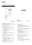
Quick Installation Guide
TK-802R
TK-1602R
Table ofofContents
Table
Contents
English .....................................................................................................
1. Before You Start ................................................................................
2. How to Install .....................................................................................
3. Operation ...........................................................................................
1
1
2
5
Troubleshooting ......................................................................................... 10
Version 11.09.2006
1. Before You Start
Package Contents
TK-802R/TK-1602R
Quick Installation Guide
Daisy-Chain Cable
Rack-Mount kit
AC Power Adapter (9V DC, 1A)
System Requirements
PS/2 Keyboard
PS/2 Mouse
VGA Compatible Monitor
KVM Cables
Windows 98/ME/2000/XP/2003 Server, Linux, and Netware
Application
Stand Alone
PC 8
PC 6
PC 4
8/16 Ports Stackable
Rack Mount KVM
Switch with OSD
PC 2
(TK-802R/TK-1602R)
Monitor
Keyboard
Mouse
PC 7
PC 3
PC 5
PC 1
Daisy-Chain
PC 8
PC 6
PC 4
PC 2
Daisy-Chain
8/16 Ports Stackable
Rack Mount KVM
Switch with OSD
Monitor
(TK-802R/TK-1602R)
Keyboard
Mouse
PC 7
PC 5
1
English
PC 3
PC 1
2. How to Install
1. Turn OFF all computers and their
peripherals, and then disconnect all
power cords.
2. Use the KVM cables to connect
each computer to the KVM switch.
Note: Do not use the supplied
daisy-chain cable to connect to
your computer. You must purchase
these KVM cables separately.
3. Connect the shared PS/2
keyboard, monitor, and PS/2
mouse to the KVM switch's
Console Port. (TK-1602R shown)
4. Connect the included AC Power
Adapter to the KVM switch and
then to a power outlet.
5. Turn ON the connected computers
one-by-one and wait until each
computer's desktop appears.
2
English
Daisy-Chain
Note:
1. Must use the daisy chain cable provided with the KVM switch
2. Only daisy chain the KVM switch with another TK-802R or TK-1602R.
3. Stackable up to 16 KVM switches
6. Connect one end of the daisychain to the Daisy chain in port on
the first (master) KVM switch.
7. Connect the opposite end of the
daisy-chain cable to the Console
port on the second (slave) switch.
8. If you have a third KVM switch,
connect one end of the daisy chain
to the Daisy chain in port on the
second KVM switch. Then connect
the opposite end of the daisy-chain
cable to the Console port on the
third (slave) switch. Repeat for
each additional switch.
9. Press Port 1 button on the first
(master) switch for 3 seconds to
initialize the daisy chain.
3
English
Note: DO NOT PRESS the port 1 button for 3 seconds or longer on any slave
switch because this will initialize only the switches downstream from this slave
switch.
10. Turn ON the connected
computers one-by-one and wait
until each computer's desktop
appears.
Rack Mount
The KVM Switch can be mounted in an EIA standard-size, 19-inch rack, which
can be placed in a wiring closet with other equipment.
Note: If you would like to mount the KVM switch to a EIA 19” equipment rack,
install the included mounting brackets to the sides of the KVM switch, secure
them with the screws provided, and then mount the KVM switch to the
equipment rack with the hardware provided by the equipment rack
manufacturer.
11. Attach the mounting brackets to
both sides of the switch and
secure them with the provided
screws.
12. Carefully position the switch onto
the rack. Align the bracket to the
screw holes on the rack, then use
the screws provided with the
equipment rack to mount the
switch.
Your installation is now complete.
4
English
3. Operation
Note: To switch between computers, you can use the front-panel push buttons
or the Hot Key commands.
LED Indicators
Bank Number: Indicates the number
or sequence of the switch when daisy
chained. This number is 01 when the
switch is not daisy chained.
Red LED light: KVM cable is
connected and PC is powering the
KVM switch.
Green LED light: Indicates the
selected PC port is active, whether
the computer is turned on or off.
Push Buttons
Press the push buttons to switch
between computers.
5
English
Hot-Key Commands
A keyboard hot-key command consists of at least three keystrokes:
Hot-Key command = ScrLk + ScrLk + Command key(s)
After pressing the ScrLk key, you have 2 seconds to press the ScrLk key again.
You then have another 2 seconds to press a command key. A beep confirms
that the KVM switch is in "Hot-Key" mode. If you do not press a key within 2
seconds, the switch will exit hot-key mode.
To select a specific PC port:
Select PC =
ScrLk + ScrLk +
A
+
B
+
Y
Bank number
+
Z
Port number
For example, to select port 1, hit the following key sequence:
Select PC = ScrLk + ScrLk +
0
+
1
+
0
+
1
For example, to select port 10 of the 10th KVM switch on a series of daisy
chained TK-1602R's you hit the following key sequence:
Select PC = ScrLk + ScrLk +
1
+
0
+
1
+
0
Note: When using the KVM switch standalone, type in 0 + 1 for the bank
number.
For a list of all the Hot-Key commands, please see the Quick Reference Sheet.
6
English
7
English
A
Change PC Name
ScrLk
Find PC by Name
---
F
R
+ ScrLk +
ScrLk
Reflash EEPROM
+ ScrLk +
B
+ ScrLk +
ScrLk
Autoscan Beep
Sound On/Off
+ ScrLk + PgDn
+ ScrLk + PgUp
ScrLk
ScrLk
Next higher
bank
Next lower
bank
+ ScrLk +
(Arrow down)
+
ScrLk
Y
Next higher
channel
+
(Arrow up)
B
+ ScrLk +
+
ScrLk
(ab) = bank number
(yz)= 2-digit channel number
ScrLk + ScrLk +
Hot-Keys
Next lower
channel
Select PC
Command
Z
---
Use arrow keys to
select and then
hit enter
-----
---
---
---
---
Use arrow keys to
select and then hit
enter
---
---
---
PgDn
PgUp
---
Press Push Button
for a specific port
to the switch
Use arrow keys to
select and then
hit enter
Use arrow keys to
select and then
hit enter
Front-panel
OSD
Description
Change the PC Name
Search presence of a
specific PC by name
Restore to Factory Defaults
except password
Toggle On/Off beep during
autoscan mode
Select the next higher bank
when multiple switches are
daisy chained
Select the next lower bank
when multiple switches are
daisy-chained
Select the next higher
connected channel. Only
works within active bank.
Select the next lower
connected channel. Only
works within active bank.
Select the active bank
(switch) and channel
(computer)
Quick Reference Sheet for TK-802R/TK-1602R
8
English
End
Press any button
or key
Press any button
or key
Press any key on keyboard
Stop Autoscan
End Autoscan activity
Specify a delay within a
range of 5~99 seconds
Autoscan through every
connected channel for
quick browsing of each
channel
Press any push
button
---
---
S
Activates OSD menu
---
---
Press on button
1 for 3 seconds
Resets/reboot/initialize
daisy-chain and activates
password protection
Description
---
Front-panel
Use arrow keys to
navigate, then hit
enter to select and
edit name
+ ScrLk +
+ ScrLk + Space Bar
+ ScrLk +
OSD
---
ScrLk
ScrLk
ScrLk
Hot-Keys
Autoscan with
Programmable
Delay Time
Autoscan
Show OSD Menu
Reset / Initialize
Command
Quick Reference Sheet for TK-802R/TK-1602R
On Screen Display (OSD) Control
To activate the OSD Menu, use the following hot-key command:
ScrLk
+ ScrLk +
Space Bar
Note: For detailed information about the operation of the OSD, please refer the
User's Guide.
9
English
Troubleshooting
Q1: Do I need to use the included external AC adapter?
A1: It is recommended that you use the included external AC adapter with the
TK-802R/TK-1602R KVM switch.
Q2: Can I connect or disconnect the KVM cables while the computers are turned
on?
A2: Yes, you can connect or disconnect the KVM cables while the computers are
turned on, because the interface is Hot-Pluggable.
Q3: Will the KVM switch restore the keyboard settings when switching between
computers?
A3: Yes, the KVM switch will restore the keyboard settings when switching
between computers. (i.e.: Caps Lock, Num Lock, etc.)
Q4: The KVM switch prompts for a password. What should I do?
A4: The default password is 00000000. Type this in. If this does not work, follow
the below procedure to reset the KVM switch:
1) Shutdown your computers
2) Unplug the power to the KVM switch
3) Press on the reset button using a pin or paper clip. The reset button is on
the back of the KVM switch, next to the power.
4) Plug the power while still pressing on the reset button.
5) Wait for the beep and let go.
If you still encounter problems or have any questions regarding the TK-802R/TK-1602R,
please contact Trendnet's Technical Support Department.
10
Limited Warranty
TRENDnet warrants its products against defects in material and
workmanship, under normal use and service, for the following lengths of
time from the date of purchase.
TK-802R/TK-1602R - 2-Year Warranty
If a product does not operate as warranted above during the applicable
warranty period, TRENDnet shall, at its option and expense, repair the
defective product or part, deliver to customer an equivalent product or
part to replace the defective item, or refund to customer the purchase
price paid for the defective product. All products that are replaced will
become the property of TRENDnet. Replacement products may be new
or reconditioned.
TRENDnet shall not be responsible for any software, firmware,
information, or memory data of customer contained in, stored on, or
integrated with any products returned to TRENDnet pursuant to any
warranty.
There are no user serviceable parts inside the product. Do not remove
or attempt to service the product by any unauthorized service center.
This warranty is voided if (i) the product has been modified or repaired
by any unauthorized service center, (ii) the product was subject to
accident, abuse, or improper use (iii) the product was subject to
conditions more severe than those specified in the manual.
Warranty service may be obtained by contacting TRENDnet office within
the applicable warranty period for a Return Material Authorization (RMA)
number, accompanied by a copy of the dated proof of the purchase.
Products returned to TRENDnet must be pre-authorized by TRENDnet
with RMA number marked on the outside of the package, and sent
prepaid, insured and packaged appropriately for safe shipment.
11
WARRANTIES EXCLUSIVE: IF THE TRENDnet PRODUCT DOES NOT
OPERATE AS WARRANTED ABOVE, THE CUSTOMER'S SOLE
REMEDY SHALL BE, AT TRENDnet'S OPTION, REPAIR OR
REPLACEMENT. THE FOREGOING WARRANTIES AND REMEDIES
ARE EXCLUSIVE AND ARE IN LIEU OF ALL OTHER WARRANTIES,
EXPRESSED OR IMPLIED, EITHER IN FACT OR BY OPERATION OF
LAW, STATUTORY OR OTHERWISE, INCLUDING WARRANTIES OF
MERCHANTABILITY AND FITNESS FOR A PARTICULAR PURPOSE.
TRENDnet NEITHER ASSUMES NOR AUTHORIZES ANY OTHER
PERSON TO ASSUME FOR IT ANY OTHER LIABILITY IN
CONNECTION WITH THE SALE, INSTALLATION MAINTENANCE OR
USE OF TRENDnet'S PRODUCTS.
TRENDnet SHALL NOT BE LIABLE UNDER THIS WARRANTY IF ITS
TESTING AND EXAMINATION DISCLOSE THAT THE ALLEGED
DEFECT IN THE PRODUCT DOES NOT EXIST OR WAS CAUSED BY
CUSTOMER'S OR ANY THIRD PERSON'S MISUSE, NEGLECT,
IMPROPER INSTALLATION OR TESTING, UNAUTHORIZED
ATTEMPTS TO REPAIR OR MODIFY, OR ANY OTHER CAUSE
BEYOND THE RANGE OF THE INTENDED USE, OR BY ACCIDENT,
FIRE, LIGHTNING, OR OTHER HAZARD.
LIMITATION OF LIABILITY: TO THE FULL EXTENT ALLOWED BY LAW
TRENDnet ALSO EXCLUDES FOR ITSELF AND ITS SUPPLIERS ANY
LIABILITY, WHETHER BASED IN CONTRACT OR TORT (INCLUDING
NEGLIGENCE), FOR INCIDENTAL, CONSEQUENTIAL, INDIRECT,
SPECIAL, OR PUNITIVE DAMAGES OF ANY KIND, OR FOR LOSS OF
REVENUE OR PROFITS, LOSS OF BUSINESS, LOSS OF
INFORMATION OR DATE, OR OTHER FINANCIAL LOSS ARISING OUT
OF OR IN CONNECTION WITH THE SALE, INSTALLATION,
MAINTENANCE, USE, PERFORMANCE, FAILURE, OR INTERRUPTION
OF THE POSSIBILITY OF SUCH DAMAGES, AND LIMITS ITS LIABILITY
TO REPAIR, REPLACEMENT, OR REFUND OF THE PURCHASE PRICE
PAID, AT TRENDnet’S OPTION. THIS DISCLAIMER OF LIABILITY FOR
DAMAGES WILL NOT BE AFFECTED IF ANY REMEDY PROVIDED
HEREIN SHALL FAIL OF ITS ESSENTIAL PURPOSE.
Governing Law: This Limited Warranty shall be governed by the laws of
the state of California.
AC/DC Power Adapter, Cooling Fan, Cables and Power Supply carry a 1
Year Warranty
12
Certifications
This equipment has been tested and found to comply with FCC and CE Rules.
Operation is subject to the following two conditions:
(1) This device may not cause harmful interference.
(2) This device must accept any interference received. Including interference that may
cause undesired operation.
Waste electrical and electronic products must not
be disposed of with household waste. Please
recycle where facilities exist. Check with you Local
Authority or Retailer for recycling advice.
NOTE: THE MANUFACTURER IS NOT RESPONSIBLE FOR ANY RADIO OR TV
INTERFERENCE CAUSED BY UNAUTHORIZED MODIFICATIONS TO THIS
EQUIPMENT. SUCH MODIFICATIONS COULD VOID THE USER’S AUTHORITY TO
OPERATE THE EQUIPMENT.
ADVERTENCIA
En todos nuestros equipos se mencionan claramente las caracteristicas del adaptador de
alimentacón necesario para su funcionamiento. El uso de un adaptador distinto al
mencionado puede producir daños fisicos y/o daños al equipo conectado. El adaptador
de alimentación debe operar con voltaje y frecuencia de la energia electrica domiciliaria
existente en el pais o zona de instalación.
TRENDnet Technical Support
US . Canada
Toll Free Telephone: 1(866) 845-3673
24/7 Tech Support
Europe (Germany . France . Italy . Spain . Switzerland . UK)
Toll Free Telephone: +00800 60 76 76 67
English/Espanol - 24/7
Francais/Deutsch - 11am-8pm, Monday - Friday MET
Worldwide
Telephone: +(31) (0) 20 504 05 35
English/Espanol - 24/7
Francais/Deutsch - 11am-8pm, Monday - Friday MET
Product Warranty Registration
Please take a moment to register your product online.
Go to TRENDnet’s website at http://www.trendnet.com
20675 Manhattan Place
Torrance, CA 90501
USA
Copyright ©2006. All Rights Reserved. TRENDnet.