1
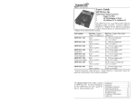
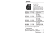
User’s Guide
S4TEF10xx-10x
Stand-Alone Media Converter
• RS-232 to Fiber
• (4) T1/E1 to Fiber
The S4TEF10xx-10x media converter can
extend signals from an RS-232 data port and
up to four (4) T1/E1 network ports over fiber.
The RS-232 and T1/E1 interfaces are independent of each other and the signals
from these ports can be sent over the fiber interface simultaneously.
The S4TEF10xx-10x is designed to be installed in pairs. For example, install one
S4TEF1011-100 as the local media converter and another S4TEF1011-100 as the
remote media converter.
All S4TEF10xx-10x models have the following copper connectors:
Connector Type
Number
Description
RS-232
T1/E1
one (1)
four (4)
6-pin, DIN serial, 3.2 m (10 ft.)*
RJ-48
The various fiber connectors are available on separate models. Both duplex and
single mode fiber optic converters are available:
Part Number
S4TEF1011-100
S4TEF1013-100
S4TEF1014-100
S4TEF1015-100
S4TEF1016-100
S4TEF1017-100
S4TEF1018-100
S4TEF1029-10x
Duplex Fiber-Optic - 100Base-FX
ST, 1300 nm multimode, 2 km (1.2 miles)*
SC, 1300 nm multimode, 2 km (1.2 miles)*
SC, 1310 nm single mode, 20 km (12.4 miles)*
SC, 1310 nm single mode, 40 km (24.8 miles)*
SC, 1310 nm single mode, 60 km (37.2 miles)*
SC, 1550 nm single mode, 80 km (49.7 miles)*
MT-RJ, 1300 nm multimode, 2 km (1.2 miles)*
(single mode, single fiber models are listed on page 2)
* Typical maximum cable distance. Actual distance is dependent upon the
physical characteristics of the network.
The chassis version of the media
converter is C4TEF10xx-10x. For more
information, see the user’s guide on-line
at: www.transition.com.
Installation . . . . . . . . . . . . . . . . . .2
Operation . . . . . . . . . . . . . . . . . .10
Cable Specifications . . . . . . . . . .12
Technical Specifications . . . . . . .14
Troubleshooting . . . . . . . . . . . . .15
Compliance Information . . . . . . .19
S4TEF10xx-10x
Part Number
Fiber-Optic - single fiber, single mode, 100Base-FX
S4TEF1029-100
SC, 1310 mn (TX)/1550 nm (RX), 20 km (12.4 miles)*
S4TEF1029-101
SC, 1550 mn (TX)/1310 nm (RX), 20 km (12.4 miles)*
S4TEF1029-100 and S4TEF1029-101 are intended to be
installed in the same link where one is the local converter
and the other is the remote converter.
S4TEF1029-102
SC, 1310 mn (TX)/1550 nm (RX), 40 km (24.8 miles)*
S4TEF1029-103
SC, 1550 mn (TX)/1310 nm (RX), 40 km (24.8 miles)*
Installation -- Continued
Configuration Switches
The S4TEF10xx-10x media converter has two (2) sets of configuration switches.
•
Set #1 sets the T1/E1 options.
•
Set #2 sets the serial options.
Switch Set #1 (upper): T1/E1 Options
S4TEF1029-102 and S4TEF1029-103 are intended to be
installed in the same link where one is the local converter
and the other is the remote converter.
* Typical maximum cable distance. Actual distance is dependent upon the
physical characteristics of the network. (TX) = transmit, (RX) = receive
Switch Set #2 (lower): Serial Options
Installation
Due to proprietary communication over fiber, the S4TEF media converter must
be installed in pairs.
Use a flat blade screwdriver to set the switches as shown:
Key:
up
Copper and Fiber Ports
The figure below illustrates the locations of the fiber port, the RS-232 data port,
and the four (4) T1/E1 ports.
Switch Set #1 - T1/E1 Options
1, 2, 3, 4 - Line Settings
Switches 1, 2, 3, and 4 are used to setup the line settings for the T1/E1 ports. The
selected setting applies to all four (4) T1/E1 channels.
T1/E1 ports
1 2 3 4
LNK
AIS
1
LNK
AIS
2
down
LNK
AIS
3
LNK
1 2 3 4
AIS
DSX-1, 100 ohm, 0-133 ft. (0-40.5 m)
DS1, 100 ohm, 0 dB LBO
DSX-1, 100 ohm, 133-266 ft. (40.5-81 m)
DS1, 100 ohm, -7.5 dB LBO
DSX-1, 100 ohm, 266-399 ft. (81-122 m)
DS1, 100 ohm, -15 dB LBO
DSX-1, 100 ohm, 399-533 ft. (122-162 m)
DS1, 100 ohm, -22.5 dB LBO
DSX-1, 100 ohm, 533-655 ft. (162-200 m)
E1, 120 ohm
4
PWR
LKF
TX 100Base-FX
fiber port
RX
RS-232
RS-232 port
NOTE: An RS-232 cable with a 6-pin DIN connector and a DB-9 connector is
included with the S4TEF10xx-10x media converter.
2
24-Hour Technical Support: 1-800-260-1312 International: 00-1-952-941-7600
J1, 110 ohm, 0-655 ft. (0-200 m)
[email protected] -- Click the “Transition Now” link for a live Web chat.
3
S4TEF10xx-10x
Installation -- Continued
Installation -- Continued
Switch Set #1 - T1/E1 Options
Switch Set #2 - Serial Options
5, 6, 7, 8 - Loop-Back Settings
1, 2, 3 - Serial Connection Speed Line Settings
The loop-back setting is used for installation and network debugging procedures.
Each of the T1/E1 ports can be individually set for loop-back mode:
Switches 1, 2, and 3 on switch set #2 are used to set the serial connection speed.
• Switch 5 controls T1/E1 port 1
• Switch 6 controls T1/E1 port 2
• Switch 7 controls T1/E1 port 3
• Switch 8 controls T1/E1 port 4
When the loop-back switch for a particular T1/E1 port is enabled, the port loops
the signal from the receive port back to the transmit port. The loop-back test
scenarios are described in detail on page 16.
6
5
1 2 3
1 2 3
1200 baud
19200 baud
2400 baud
38400 baud
4800 baud
57600 baud
9600 baud
115200 baud
up
up
Disable Loop-Back on T1/E1 port 1
Disable Loop-Back on T1/E1 port 2
down
down
Enable Loop-Back on T1/E1 port 1
Enable Loop Back on T1/E1 port 2
8
7
Disable Loop-Back on T1/E1 port 3
down
Enable Loop-Back on T1/E1 port 4
up - Disable parity.
down - Enable parity.
9 - Transmit AIS
up - Enables the transmit AIS (Alarm Indication
Signal) on loss of the carrier signal. This function
is un-framed and applies to ALL channels, both Enable
copper and fiber.
4
up
When parity is enabled, an additional bit is added to
the 8-bit signal to identify whether the signal is sent
successfully. Use switch 5 to send odd or even Disable Parity
signal parity.
Disable Loop-Back on T1/E1 port 4
down
Enable Loop-Back on T1/E1 port 3
4. Enable / Disable Parity
up
up
down
Enable Parity
9
up
5
5. Parity Select
up - Select odd serial parity.
down
down - Disables the transmit AIS function.
up
Odd Serial Parity
down - Select even serial parity.
Disable
This switch is inactive if switch 4 is (up).
down
Even Serial Parity
10 - RS-232 Port Mode
up - Data port mode (normal operation).
Transmits data to a desk top computer or other
data collection device
down - Local (auxiliary) management mode. See
the SNMP section (page 11) for the commands
that are supported via the RS-232 connector.
4
10
up
Data port mode
down
Local management mode
24-Hour Technical Support: 1-800-260-1312 International: 00-1-952-941-7600
[email protected] -- Click the “Transition Now” link for a live Web chat.
5
S4TEF10xx-10x
Installation -- Continued
Installation -- Continued
Hardware/Software Jumper
Switch Set #2 - Serial Options
switches 6, 7, 8, & 9 are not in use
9 - not in use
Hardware Mode
To set the jumper:
1.
10 - Fiber Loop-Back
up - Disabled fiber loop-back.
down - Enabled fiber loop-back.
The loop-back setting is used for installation
and network debugging procedures. When
the fiber loop-back function is enabled, the
fiber port loops all T1/E1 signals from the
receive ports back to the transmit ports. The
loop-back test scenarios are described in
detail on page 17.
The media converter mode is determined by
the most-recently saved, on-board
microprocessor settings.
Software Mode
H
Software
8 - not in use
S
Hardware The media converter mode is determined by
the switch settings (see pages 3 - 6).
6 7 8 9
S
7 - not in use
H
The hardware/software jumper is inside the media converter housing and is
located near the back end of the upper circuit board.
6 - not in use
10
2.
Locate the hardware/software jumper.
3.
Using small needle-nosed pliers or similar
device, move the jumper to the desired position
(see above).
4.
Carefully replace the cover on the media
converter and replace the four (4) screws that
secure the cover to the media converter.
up
Disables Loop-Back
Using a small screwdriver, remove the four (4)
screws that secure the cover and carefully
remove the cover from the media converter.
down
Enables Loop-Back
Power the Media Converter
hardware/software
jumper
1.
Connect the barrel connector on the power adapter to the media
converter’s power port (located on the back of the media converter).
2.
Connect the power adapter plug to AC power.
3.
Verify that the media converter is powered by observing the illuminated
LED power indicator light.
NOTE: For DC power, consult the user’s guide for the Transition Networks
SPS1872-xx DC external power supply.
6
24-Hour Technical Support: 1-800-260-1312 International: 00-1-952-941-7600
[email protected] -- Click the “Transition Now” link for a live Web chat.
7
S4TEF10xx-10x
Installation -- Continued
Installation -- Continued
Install the T1/E1 Cable
Install the Fiber Cable
1.
Locate or build ITU-compliant copper cable with straight-through RJ-48
connectors installed at both ends. (See page 13 for the proper cable
specifications for your network application.)
2.
Connect the RJ-48 connector at one end of the cable to one of the T1/E1
ports on the S4TEF10xx-10x media converter.
3.
Connect the RJ-48 connector at the other end of the cable to the T1/E1
port on the other device.
Dry-Contact Relay
All four T1/E1 ports are equipped with an
RJ-48 dry-contact relay. The relay closes if
the power is lost or if any of the individual
T1/E1/E1 links are lost. The operational
rating on pins 3 and 6 are 0-30 VDC, 100
mA (maximum).
T1/E1 port
3
1.
Locate or build ITU- compliant 100Base-FX fiber cable with male, twostranded TX to RX connectors installed at both ends.
2.
Connect the fiber cables to the local S4TEF10xx-10x media converter as
described:
• Connect the male TX cable connector to the female TX port.
• Connect the male RX cable connector to the female RX port.
3.
Connect the fiber cables to the remote S4TEF10xx-10x media converter
as described:
• Connect the male TX cable connector to the female RX port.
• Connect the male RX cable connector to the female TX port.
RJ-48C connector
Connect the fiber cable
to the local media
converter as shown.
relay
6
Install the RS-232 Data Cable (included)
1.
Use the enclosed RS-232 data cable with a male, DIN 6-pin connector
on one end and a DB-9 connector installed on the other end.
2.
Connect the DIN 6-pin connector to the RS-232 port on the S4TEF10xx10x media converter.
3.
Connect the DB-9 connector at the other end of the cable to the RS-232
port on a computer or other device that is used to collect and display
data.
Connect the fiber cable
to the remote media
converter as shown
RX
RX
TX
TX
Connect the 6-pin DIN
connector to the media
converter as shown.
Connect the DB-9
connector to the
computer
RS-232 data cable (enclosed)
8
24-Hour Technical Support: 1-800-260-1312 International: 00-1-952-941-7600
[email protected] -- Click the “Transition Now” link for a live Web chat.
9
S4TEF10xx-10x
Operation
Operation -- Continued
T1/E1 LEDs
Remote Management Function
Each T1/E1 link has a pair of LEDs embedded in the RJ-48 connector that
monitor the status of the link.
LNK LED (green)
On = T1/E1 link detected.
AIS LED (amber)
The S4TEF10xx-10x, can be remotely managed when connected via fiber cable
to a local C4TEF10xx-10x slide-in-module media converter that is installed in a
managed Transition Networks PointSystem™ chassis. The SNMP section
(below) lists the commands that can be used to monitor and manage a
networked S4TEF10xx-10x media converter at a remote location. For more
details, see the C4TEF10xx-10x user’s guide on-line at: www.transition.com.
On = AIS (Alarm Indication Signal) detected. Failure of the device
connected to the T1/E1 port.
SNMP
See the on-line documentation that comes with Transition Networks
FocalPoint™ software for applicable commands and usage.
LNK
T1/E1 LEDs
AIS
LNK
1
AIS
2
LNK
AIS
3
LNK
AIS
4
PWR
LKF
TX 100Base-FX
RX
RS-232
fiber LEDs
Fiber Network LEDs
Use the status LEDs next to the fiber port to monitor the media converter and
the fiber network connections.
LKF (fiber link)
On = Fiber link connection.
Flashing = Fiber network activity.
PWR (power)
On = Connection to external AC or DC power.
10
24-Hour Technical Support: 1-800-260-1312 International: 00-1-952-941-7600
Use SNMP at an attached terminal or at a remote location to monitor the media
converter by monitoring:
• Media converter power
• Fiber link status
• Copper link status for each T1/E1 (AIS, link)
• RS-232 status (speed, bits, parity, stop)
• AIS detected on fiber link
• All hardware switch settings
• Model #, serial #, PIC revision, HW revision, group string, connectors
Also, use SNMP to enter network commands that:
• Local and remote fiber loop-back
• Local and remote T1/E1 loop-back for each channel
• T1/E1 line options (DS1, DSX-1, J1, D1, AIS)
• RS-232 settings (speed, bits, parity, stop)
• T1/E1 monitor modes and loop-back modes
• Boot-load firmware (local unit only)
The local (auxiliary) factory maintenance interface via the RS-232 connector
supports:
• Switch selection for the RS-232 interface
• Access to all local and remote status information
• Perform all local and remote commands
• Operate at selected baud rates
[email protected] -- Click the “Transition Now” link for a live Web chat.
11
S4TEF10xx-10x
Cable Specifications
Cable Specifications -- Continued
The physical characteristics must meet or exceed ITU specifications.
Fiber Cable
Bit Error Rate:
Single mode fiber (recommended):
Multimode fiber (recommended):
Multimode fiber (optional):
<10-9
9 µm
62.5/125 µm
100/140, 85/140, 50/125 µm
S4TEF1011-100
Fiber Optic Transmitter Power:
Fiber Optic Receiver Sensitivity:
Link Budget:
1300 nm multimode
min: -19.0 dBm max: -14.0 dBm
min: -30.0 dBm max: -14.0 dBm
11.0 dB
S4TEF1013-100
Fiber Optic Transmitter Power:
Fiber Optic Receiver Sensitivity:
Link Budget:
1300 nm multimode
min: -19.0 dBm max: -14.0 dBm
min: -30.0 dBm max: -14.0 dBm
11.0 dB
T1/E1 Cable
Category 3: (minimum requirement)
Connector:
Electrical network connection:
Mechanical arrangement:
Usage:
Interface codes:
Cable type:
Long Haul T1/E1:
E1:
J1:
DSX-1:
RJ-48C
Single 4-wire (Tip/Ring - Tip1/Ring1)
8-position miniature modular jack
1.544 Mb/s access lines
04DU9 (any applicable)
0db, -7.5dp, -15db, -22db
E1 3.0V, 120 ohm
0-655’, 110 ohm
0-133’, 133-266’, 266-399’,
399-533’, 533-655’, 100 ohm
(ring) R
1
1
R
(tip) T
2
2
T
3
3
(ring) R1
4
4
R1
(tip) T1
5
5
T1
S4TEF1014-100
Fiber-optic Transmitter Power:
Fiber-optic Receiver Sensitivity:
Link Budget:
1310 nm single mode
min: -15.0 dBm max: -8.0 dBm
min: -31.0 dBm max: -8.0 dBm
16.0 dB
S4TEF1015-100 (long haul)
Fiber-optic Transmitter Power:
Fiber-optic Receiver Sensitivity:
Link Budget:
1310 nm single mode
min: -8.0 dBm
max: -2.0 dBm
min: -34.0 dBm max: -7.0 dBm
26.0 dB
6
6
7
7
8
8
S4TEF1016-100 (extra long haul)
S4TEF1017-100 (long wave length)
Fiber-optic Transmitter Power:
Fiber-optic Receiver Sensitivity:
Link Budget:
1310 nm single mode
1550 nm single mode
min: -5.0 dBm
max: 0.0 dBm
min: -34.0 dBm max: -7.0 dBm
29.0 dB
to the
network
from the
media converter
S4TEF1018-100
Fiber-optic Transmitter Power:
Fiber-optic Receiver Sensitivity:
Link Budget:
1300 nm multimode
min: -19.0 dBm max: -14.0 dBm
min: -30.0 dBm max: -14.0 dBm
11.0 dB
S4TEF1029-100
S4TEF1029-101
Fiber-optic Transmitter Power:
Fiber-optic Receiver Sensitivity:
Link Budget:
1310 nm (TX)/1550 nm (RX) simplex
1550 nm (TX)/1310 nm (RX) simplex
min: -13.0 dBm max: -6.0 dBm
min: -32.0 dBm max: -3.0 dBm
19.0 dB
S4TEF1029-102
S4TEF1029-103
Fiber-optic Transmitter Power:
Fiber-optic Receiver Sensitivity:
Link Budget:
1310 nm (TX)/1550 nm (RX) simplex
1550 nm (TX)/1310 nm (RX) simplex
min: -8.0 dBm
max: -3.0 dBm
min: -33.0 dBm max: -3.0 dBm
25.0 dB
Transmit
dry contact A
Receive
dry contact B
(Not Used)
RS-232 Cable (included)
Connectors:
Gauge:
Attenuation:
Differential characteristic impedance:
Maximum cable distance:
6-pin DIN and DB-9
24 to 22 AWG
20 dB/1000 ft. @ 10 MHz
100 ohm +/- 10% @ 10 MHz
<10 ft (3.2 m) @ 56 kb/s or higher
1
Signal Ground 3 & 5
Transmit Signal 1
Receive signal 2
3
5
6
2 Receive Data
7
7 Request Data
2
1
3
2
8
4
4
6
9
Clear to send 9
5
DIN 6-Pin
3 Transmit Data
5 Signal Ground
DB-9
The fiber optic transmitters on this device meets Class I Laser safety
requirements per IEC-825/CDRH standards and complies with 21
CFR1040.10 and 21CFR1040.11.
12
24-Hour Technical Support: 1-800-260-1312 International: 00-1-952-941-7600
[email protected] -- Click the “Transition Now” link for a live Web chat.
13
S4TEF10xx-10x
Technical Specifications
Troubleshooting
For use with Transition Networks Model S4TEF10xx-10x or equivalent.
Standards
G.703, AMI/B8Zs/HDB3
Data Rate
Fiber: 100 Mb/s
Dimensions
3.7" x 4.7" x 1.8" (93 mm x 120 mm x 47 mm)
Weight
1 lb. (0.45 kg) (approximate)
Power Consumption
6.0 watts
Power Supply
12 VDC, 0.8 Amp (North. Am., EU, Latin Am., Japan)
12 VDC, 1.25 Amp (UK, Australia, N.Z., South Africa)
(The external power supply provided with this product
is UL listed by the power supplier’s manufacturer.)
Environment
Warranty
Tmra*:
Storage Temperature:
Humidity:
Altitude:
0 to 50°C (32 to 122°F )
-40 to 85°C (-40 to 185°F)
5 to 95%, non condensing
to 10,000 feet
If the media converter fails, isolate and correct the failure by determining the
answers to the following questions and then taking the indicated action:
1.
• Ensure that the power adapter is the proper type of voltage and cycle
frequency for the outlet (See “Power Supply” on page 14.)
• Ensure the power adapter is properly installed in the media converter
and in the grounded outlet.
• Contact Tech Support: 1-800-260-1312, Int’l: 00-1-952-941-7600.
YES
• Proceed to step 2.
2.
Lifetime
Is the “LKF” LED illuminated?
NO
• Check the fiber cables for proper connection.
• Verify that the TX and RX cables on the local media converter are
connected to the RX and TX ports, respectively, on the remote media
converter.
• Contact Tech Support: 1-800-260-1312, Int’l: 00-1-952-941-7600.
*Manufacturer’s rated ambient temperature.
The information contained in this user’s guide is subject to change. For the most
up-to-date information on the S4TEF10xx-10x media converter, see the user’s
guide on-line at: www.transition.com.
Product is certified by the manufacturer to comply with DHHS Rule 21/CFR,
Subchapter J applicable at the date of manufacture.
Is the “PWR” LED illuminated?
NO
YES
• Proceed to step 3.
CAUTION: Visible and invisible laser radiation when open. Do not stare into
beam or view directly with optical instruments.
3.
Is the “LNK” LED on a T1/E1port (with a copper cable installed)
illuminated?
NO
CAUTION: Use of controls, adjustments or the performance of procedures other
than those specified herein may result in hazardous radiation exposure.
• Check the copper cable connected to that T1/E1 port for proper
connection.
• Contact Tech Support: 1-800-260-1312, Int’l: 00-1-952-941-7600.
YES
• Proceed to step 4.
Optional Accessories
The following items are available from Transition Networks
Part Number
SPS-1872-SA
WMBL
WMBV
WMBD
Description
Optional External Power Supply; 18-72VDC Stand-Alone
Output: 12.6VDC, 1.0 A
Optional Wall Mount Bracket; 4.0 in. (102 mm)
Optional Vertical Mount Bracket; 5.0 in. (127 mm)
Optional DIN Rail Mount Bracket; 5.0 in. (127 mm)
4.
Is the “AIS” LED on a T1/E1 port (with a copper cable installed)
illuminated?
YES
• The device connected to the T1/E1 port has failed. Correct the device
failure.
• Contact Tech Support: 1-800-260-1312, Int’l: 00-1-952-941-7600.
NO
• Proceed to step 5.
14
24-Hour Technical Support: 1-800-260-1312 International: 00-1-952-941-7600
[email protected] -- Click the “Transition Now” link for a live Web chat.
15
S4TEF10xx-10x
Troubleshooting -- Continued
Local
Converter
Fiber
Remote
Converter
T1
T1
Local
Converter
Fiber
Remote
Converter
T1
Bit Error Test
Equipment
Remote
Device
• Verify the remote T1/E1 connection at the local converter by starting a
remote loop-back at the local converter:
- SW mode: enter the remote T1/E1 loop-back command at the local
converter. (HW mode is not available.)
• Use a bit error test unit to run a bit error test.
T1
Local
Converter
Fiber
Remote
Converter
T1
Local
Converter
Fiber
Remote
Converter
T1
Remote
Device
T1
• Verify the remote fiber connection by starting a local fiber loop-back:
- HW mode: set the local converter to fiber loop-back (see page 7).
- SW mode: enter the remote fiber loop-back command.
• Use a bit error test unit to run a bit error test.
T1
Local
Converter
Fiber
Remote
Converter
T1
• Contact Tech Support: 1-800-260-1312, Int’l: 00-1-952-941-7600.
NO
• Contact Tech Support: 1-800-260-1312, Int’l: 00-1-952-941-7600.
Remote
Device
Bit Error Test
Equipment
• Verify the remote T1/E1 connection at the remote converter by starting a
remote loop-back at the remote converter:
- SW mode: enter the remote T1/E1 loop-back command at the remote
converter. (HW mode is not available.)
• Use a bit error test unit to run a bit error test.
• Verify the local fiber connection by starting a remote fiber loop-back:
- HW mode: set the remote converter to fiber loop-back (see page 7).
- SW mode: enter the remote fiber loop-back command.
• Use a bit error test unit to run a bit error test.
Bit Error Test
Equipment
T1
Remote
Device
Bit Error Test
Equipment
• Verify the local T1/E1 connection at the local converter by starting a
local loop-back at the local converter:
- HW mode: set the local converter to T1/E1 loop-back (see page 4).
- SW mode: enter the local T1/E1 loop-back command at the local
converter.
• Use a bit error test unit to run a bit error test.
6. Is data transfer failing on the fiber port?
YES
Bit Error Test
Equipment
5. Is data transfer failing on one of the T1/E1 ports?
YES
Remote
Device
Troubleshooting -- Continued
16
T1
Local
Converter
Fiber
Remote
Converter
T1
Bit Error Test
Equipment
Remote
Device
• Verify the local T1/E1 connection at the remote converter by starting a
local loop-back at the remote converter:
- HW mode: set the remote converter to T1/E1 loop-back (see page 4).
- SW mode: enter the local T1/E1 loop-back command at the remote
converter.
• Use a bit error test unit to run a bit error test.
24-Hour Technical Support: 1-800-260-1312 International: 00-1-952-941-7600
[email protected] -- Click the “Transition Now” link for a live Web chat.
17
S4TEF10xx-10x
Contact Us
Compliance Information
Technical Support
Technical support is available 24 hours a day.
US and Canada:
1-800-260-1312
International:
00-1-952-941-7600
CISPR22/EN55022 Class A + EN55024
CE Mark
FCC Regulations
Transition Now
Chat live via the Web with Transition Networks Technical Support.
Log onto www.transition.com and click the Transition Now link.
Web-Based Seminars
Transition Networks provides seminars via live web-based training.
Log onto www.transition.com and click the Learning Center link.
E-Mail
Ask a question anytime by sending an e-mail to our technical support staff.
[email protected]
This digital apparatus does not exceed the Class A limits for radio noise for digital apparatus
set out on the radio interference regulations of the Canadian Department of Communications.
Le présent appareil numérique n'émet pas de bruits radioélectriques dépassant les limites
applicables aux appareils numériques de la Class A prescrites dans le Règlement sur le
brouillage radioélectrique édicté par le ministère des Communications du Canada.
Warning This is a Class A product. In a domestic environment this product may cause radio
interference in which case the user may be required to take adequate measures.
Achtung! Dieses ist ein Gerät der Funkstörgrenzwertklasse A. In Wohnbereichen können
bei Betrieb dieses Gerätes Rundfunkstörungen auftreten, in diesem Fäll ist der Benutzer für
Gegenmaßnahmen verantwortlich.
Attention! Ceci est un produit de Classe A. Dans un environment domestique, ce produit
risque de créer des interférences radioélectriques, il appartiendra alors à l'utilsateur de
prende les measures spécifiques appropriées.
Declaration of Conformity
Name of Mfg:
Transition Networks
6475 City West Parkway, Minneapolis MN 55344 U.S.A.
Model:
S4TEF10xx-10x Series Media Converters
Part Number(s):
S4TEF1011-100, S4TEF1013-100, S4TEF1014-100,
S4TEF1015-100, S4TEF1016-100, S4TEF1017-100,
S4TEF1018-100, S4TEF1029-100, S4TEF1029-101,
S4TEF1029-102, S4TEF1029-103
Regulation:
EMC Directive 89/336/EEC
Purpose: To declare that the S4TEF10xx-10x to which this declaration refers is in
conformity with the following standards.
EN 55022:1994 Class A; FCC Part 15 Subpart B; EN 55024:1998+A1+A13564:2002;
21 CFR subpart J; EN 61000-3-2:2001; EN 61000-4-2, 4-3, 4-4, and 4-6
I, the undersigned, hereby declare that the equipment specified above conforms to the above
Directive(s) and Standard(s).
August 2007
18
Canadian Regulations
European Regulations
Address
Transition Networks
6475 City West Parkway
Minneapolis, MN 55344, U.S.A.
telephone:
952-941-7600
toll free:
800-526-9267
fax:
952-941-2322
Stephen Anderson, Vice-President of Engineering
This equipment has been tested and found to comply with the limits for a Class A digital
device, pursuant to part 15 of the FCC rules. These limits are designed to provide reasonable
protection against harmful interference when the equipment is operated in a commercial
environment. This equipment generates, uses, and can radiate radio frequency energy and, if
not installed and used in accordance with the instruction manual, may cause harmful
interference to radio communications. Operation of this equipment in a residential area is
likely to cause harmful interference, in which case the user will be required to correct the
interference at the user's own expense.
Date
24-Hour Technical Support: 1-800-260-1312 International: 00-1-952-941-7600
In accordance with European Union Directive 2002/96/EC of the European
Parliament and of the Council of 27 January 2003, Transition Networks will
accept post usage returns of this product for proper disposal. The contact
information for this activity can be found in the 'Contact Us' portion of this
document.
VCCI Class 1 Compliance
This equipment is in the 1st Class category (information equipment to be used in commercial
and/or industrial areas) and conforms to the standards set by the Voluntary Control Council
For Interference by Data Processing
Equipment and Electronic Office
Machines aimed at preventing radio
interference in commercial and/or
industrial areas. When used in a
residential area or in an adjacent area
thereto, interference may be caused to
radio and TV receivers, etc. Read the
instructions for correct handling.
[email protected] -- Click the “Transition Now” link for a live Web chat.
19
Trademark Notice
All trademarks and registered trademarks are the property of their respective owners.
Copyright Restrictions
© 2005 Transition Networks.
All rights reserved. No part of this work may be reproduced or used in any form or by any
means - graphic, electronic, or mechanical - without written permission from Transition
Networks.
Printed in the U.S.A.
33307.C