1
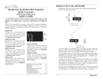
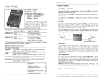
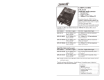
COMPLIANCE INFORMATION
Minneapolis, MN 55344 USA
UL Listed
C-UL Listed (Canada)
CISPR/EN55022 Class A
10BASE-FL Ethernet™
FCC Regulations
This equipment has been tested and found to comply with the limits for a class A digital device, pursuant
to part 15 of the FCC rules. These limits are designed to provide reasonable protection against harmful
interference when the equipment is operated in a commercial environment. This equipment generates,
uses, and can radiate radio frequency energy and, if not installed and used in accordance with the
instruction manual, may cause harmful interference to radio communications. Operation of this
equipment in a residential area is likely to cause harmful interference, in which case the user will be
required to correct the interference at the user’s own expense.
Unmanaged Fiber Hub with AUI, BNC or Fiber Uplink
E-FL-HB-0800, E-FL-HB-0400
USER’S GUIDE
Canadian Regulations
This digital apparatus does not exceed the Class A limits for radio noise for digital apparatus set out on
the radio interference regulations of the Canadian Department of Communications.
Le présent appareil numérique n'émet pas de bruits radioélectriques dépassant les limites applicables
aux appareils numériques de la class A prescrites dans le Règlement sur le brouillage radioélectrique
édicté par le ministère des Communications du Canada.
European Regulations
Warning
This is a Class A product. In a domestic environment this product may cause radio interference in which
case the user may be required to take adequate measures.
Achtung !
Dieses ist ein Gerät der Funkstörgrenzwertklasse A. In Wohnbereichen können bei Betrieb dieses Gerätes
Rundfunkstörungen auftreten, in weichen Fällen der Benutzer für entsprechende Gegenmaßnahmen
werantwortlich ist.
Attention !
Ceci est un produit de Classe A. Dans un environment domestique, ce produit risque de créer des
interférences radioélectriques, il appartiendra alors à l’utilsateur de prende les measures spécifiques
appropriées
VCCI Class 1 Compliance
This equipment is in the 1st Class category (information equipment to be used in commercial and/or
industrial areas) and conforms to the standards set by the Voluntary Control Council For Interference by
Data Processing Equipment and Electronic Office Machines aimed at preventing radio interference in
commercial and/or industrial areas. When used in a residential area or in an adjacent area thereto,
interference may be caused to radio and TV receivers, etc. Read the instructions for correct handling.
The rack-mountable E-FL-HB-0800 and E-FL-HB-0400 series unmanaged
Ethernet™ fiber hubs allow the network administrator to set up network
workgroups connected over fiber and to install an OPTIONAL backbone
uplink adapter connection to the workgroups through 10BASE-5 AUI,
10BASE-2 BNC OR 10BASE-FL ST fiber connectors.
E-FL-HB-0800, E-FL-HB-0800(SC)
10BASE-FL
BB
PWR
STAT
COL
ACT
1
3
2
4
5
6
7
8
1
2
3
4
6
5
7
8
The E-FL-HB-0800 hub provides eight (8) Ethernet™ ST OR SC fiber
connections to terminal devices plus space at the back for an optional
backbone uplink adapter.
E-FL-HB-0400, E-FL-HB-0400(SC)
10BASE-FL
BB
PWR
STAT
COL
ACT
1
2
3
1
4
2
3
4
The E-FL-HB-0400 hub provides four (4) Ethernet™ ST OR SC fiber
connections to terminal devices plus space at the back for an optional
backbone uplink adapter.
CAUTION: RJ connectors are NOT INTENDED FOR CONNECTION TO THE
PUBLIC TELEPHONE NETWORK. Failure to observe this caution could result in
damage to the public telephone network.
Der Anschluss dieses Gerätes an ein öffentlickes Telekommunikationsnetz in den EG-Mitgliedstaaten
verstösst gegen die jeweligen einzelstaatlichen Gesetze zur Anwendung der Richtlinie 91/263/EWG zur
Angleichung der Rechtsvorschriften der Mitgliedstaaten über Telekommunikationsendeinrichtungen
einschliesslich der gegenseitigen Anerkennung ihrer Konformität.
Trademark Notice
All registered trademarks and trademarks are the property of their respective owners.
Copyright Restrictions
© 1999 TRANSITION Networks.
All rights reserved. No part of this work may be reproduced or used in any form or by any means –
graphic, electronic, or mechanical – without written permission from TRANSITION Networks.
Printed in the U.S.A.
33160.A
BACKBONE UPLINK ADAPTERS Optional devices ordered separately that, when
installed, provide one of the following Ethernet™ backbone uplink connections:
MA0A
• AUI connector to transceiver or to 10BASE-5 “thick-net” coaxial cable
MA0B
• BNC connector to 10BASE-2 “thin-net” coaxial cable
MA0F
• ST connector to multimode fiber
E-FL-HB-0x00 in the Network . . . . .2
Installation . . . . . . . . . . . . . . . . . . . .4
Operation . . . . . . . . . . . . . . . . . . . .11
Fault Isolation and Correction . . . .12
Cable Specifications . . . . . . . . . . . .14
Technical Specifications . . . . . . . . .15
Compliance Information . . . . . . . . .16
E-FL-HB-0x00 IN THE NETWORK
Install one E-FL-HB-0x00
hub and use fiber cable to
set up a workgroup by
connecting the hub to
terminal devices.
TECHNICAL SPECIFICATIONS
10BASE-FL
BB
PWR
STAT
COL
ACT
1
2
3
4
5
6
7
1
8
2
3
4
6
5
7
Standards
IEEE 802.3
Dimensions
17.25" x 8.5" x 1.7"
(437 mm x 216 mm x 43 mm)
8
Power
Input Range:
Install an optional backbone
uplink adaptor at the back of
the hub and use 10BASE-2,
10BASE-5, or fiber cable to
connect the workgroup to a
network backbone.
to hub, switch, or router
100 to 240 VAC at 50 or 60 Hz, 3.0 A maximum.
Rated at 40 watts maximum.
Environment
Operating Temperature:
Storage Temperature:
Humidity
Altitude
Warranty
Lifetime
0° to 50°C (32° to 122° F )
-15° to 65°C (5° to 149° F )
5% to 95%, non condensing
0 to 10,000 feet
10BASE-FL
BB
PWR
STAT
COL
ACT
1
2
3
4
5
6
7
3
2
1
8
4
7
6
5
8
DECLARATION OF CONFORMITY
Cascade two repeater hubs by
connecting fiber cable from a connector
at the front of the first hub to a
connector at the front of the second
hub.
10BASE-FL
BB
PWR
STAT
COL
ACT
1
2
3
4
5
6
Name of Mfg:
to hub, switch or router
10BASE-FL
BB
7
8
1
2
3
4
5
6
7
8
PWR
STAT
COL
ACT
1
2
3
4
5
6
7
8
1
2
3
4
5
6
7
8
Transition Networks
6475 City West Parkway, Minneapolis MN 55344 USA
Model:
E-FL-HB-0x00 Series Unmanaged Fiber Hub
Part Number:
E-FL-HB-0800, E-FL-HB-0800(SC), E-FL-HB-0400,
E-FL-HB-0400(SC)
Regulation:
EMC Directive 89/336/EEC
Purpose: To declare that the E-FL-HB-0800 or E-FL-HB-0400 to which this
declaration refers is in conformity with the following standards.
EMC-CISPR 22: 1985 Class A; EN 55022: 1988 Class A; EN 50082-1:1992;
EN 60950 A4:1997; IEC 801.2, IEC 801.3, and IEC 801.4; IEC 950
I, the undersigned, hereby declare that the equipment specified above conforms to the
above Directive(s) and Standard(s).
_November 10, 1999_____
Stephen Anderson, Vice-President of Engineering
Date
E-FL-HB-0x00 in Half-Duplex Network
CABLE SPECIFICATIONS
10BASE-2 Cable Specifications
10BASE-2 CABLE CHARACTERISTICS:
Cable type:
Stranded Coaxial RG58 (ThinNet)
Impedance:
50 Ω @ 10 MHz
Mutual Capacitance:
24 pF/ft ±20% @ 10 MHz
Maximum Cable Length:
185 meters (610 feet)
Maximum number network connections:
30
Minimum distance between connections:
0.5 meters (1.6 feet)
Terminate 10BASE-2 cable at one end using a 50 ohm terminator and at the other end
using a 50 ohm terminator grounded to earth ground.
The 5-4-3 Rule applies separately to each collision domain. NOTE: A
collision domain is any Carrier Sense Multiple Access with Collision Detection
(CSMA/CD) network in which a collision will occur if two attached stations
transmit at the same time. A segment is the cable connection between two
network interfaces.
USING THE 5-4-3 RULE:
The 5-4-3 Rule allows no more than five segments in any 10-Mb/sec
Ethernet collision domain, no more than four repeaters (hubs) and no
more than three populated segments (10Base-2 or 10BASE-5 coaxialcable installations).
To determine the size of the collision domain by assigning segment
numbers to cable connections, determine the two network devices in a
transmission path that are separated by the greatest number of segments.
Define a segment path between the network devices by labeling the
cable connection to the first device “segment 1” and numbering each
segment in the path to the last network device, up to “segment n” (n =
total number of segments ≤ 5). Verify that no segment path in the entire
collision domain contains more than n ≤ 5 segments.
AUI/10BASE-5 Cable Specifications
10BASE-5 CABLE CHARACTERISTICS:
Cable type:
RG8 Solid Coaxial (ThickNet)
Impedance:
50 Ω @ 10 MHz
Capacitance:
26pF/ft
Maximum Cable Length:
500 meters (1650 feet)
Maximum number network connections:
100
Minimum distance between connections:
2.5 meters (8.2 feet)
Terminate 10BASE-5 cable at one end using a 50 ohm terminator and at the other end
using a 50 ohm terminator grounded to earth ground.
AUI CABLE AND CONNECTOR SPECIFICATIONS
The cable is a special 4-pair individually shielded with an overall braided shield.
Maximum AUI Cable Length:
50 meters (165 feet)
4
AUI CONNECTOR CHARACTERISTICS:
AUI Port:
AUI Connection:
Connector Legend:
Male DB-15 with locking posts.
Cable shell must be grounded.
1 Logic Ref.
6 Power Return
2 Collision+
7 N/C
3 Transmit+
8 Logic Ref.
4 Logic Ref.
9 Collision-5 Receive+
10 Transmit-
11
12
13
14
15
Logic Ref
Receive
Power
Logic Ref.
N/C
3
4
10BASE-FL
BB
PWR
STAT
COL
ACT
1
2
3
4
5
6
7
3
2
1
8
4
6
5
7
8
10BASE-FL
BB
PWR
STAT
COL
ACT
1
2
3
4
5
6
7
3
2
1
8
4
5
6
7
10BASE-FL Cable Specifications
Fiber Optic Cable Recommended:
Optional:
Wavelength
Fiber Optic Transmitter Power:
Fiber Optic Receiver Sensitivity:
Typical Maximum Cable Distance*:
62.5 / 125 µm multimode fiber
100 / 140 µm multimode fiber
85 / 125 µm multimode fiber
50 / 125 µm multimode fiber
1300 nM
min: -__._ dBm
max: -__._ dBm
min: -__._ dBm
max: -__._ dBm
2000 meters (6600 feet)
3
4
3
10BASE-FL
BB
PWR
STAT
COL
ACT
1
2
3
4
5
6
7
8
1
2
3
4
5
6
7
8
10BASE-FL
BB
PWR
STAT
COL
ACT
1
2
3
4
5
6
7
8
1
*Actual distance dependent upon physical characteristics of network installation.
2
3
4
5
6
7
8
2
1
5
4
8
INSTALLATION
6.
NO
Optionally Install Backbone Uplink Adapter
•
WARNING: Remove AC line cord from power source before installing
backbone uplink adaptor in E-FL-HB-0x00. Failure to observe this warning
could result in personal injury or death.
CAUTION: Wear a grounding device and observe electrostatic discharge
precautions when installing backbone uplink adaptor in the E-FL-HB-0x00.
Failure to observe this caution could result in damage to, and subsequent
failure of, backbone uplink adaptor.
•
•
Disconnect and reconnect the backbone cable to restart the
initialization process.
Restart the attached network device to restart the initialization
process.
Contact Technical Support: (800) 260-1312.
YES
•
7.
To install the backbone uplink adapter in the E-FL-HB-0x00:
1.
Is the B(ack)B(one) ACT(ivity) LED illuminated?
Continue at step 7.
Is one (or more) of the 10BASE-FL STAT(us) LEDs illuminated
continuously?
YES
Locate backbone uplink adapter plate at back of E-FL-HB-0x00.
•
Continue at step 10.
NO
•
8.
Backbone Uplink Adapter Plate
2.
Carefully slide backbone uplink adapter, component side up, into
installation space revealed by removal of backbone uplink adapter
plate.
Does one (or more) of the 10BASE-FL STAT(us) LEDs
continuously blink ONCE?
YES
Remove backbone uplink adapter plate by using flatblade
screwdriver to remove two (2) screws that secure backbone uplink
adapter plate to back of E-FL-HB-0x00.
•
•
•
•
NOTE: Retain screws for step 5. (Optionally discard backbone
uplink adapter plate.)
3.
Continue at step 8.
Check fiber cables for proper connection.
Verify that TX and RX cables on E-FL-HB-0x00 are connected to RX
and TX ports, respectively, on terminal device. (See page 9.)
Ensure that terminal device(s) is/are powered.
Contact Technical Support: (800) 260-1312.
NO
•
9.
CAUTION: Do NOT force connection. Failure to observe this caution
could result in equipment damage and subsequent failure.
Continue at step 9.
Does one (or more) of the 10BASE-FL STAT(us) LEDs
continuously blink TWICE?
YES
•
•
The port is (or ports are) partitioned; investigate the attached
terminal device(s).
Contact Technical Support: (800) 260-1312.
NO
•
10.
Continue at step 10.
Is one (or more) of the 10BASE-FL ACT(ivity) LEDs illuminated?
YES
•
The port is (or ports are) operational and receiving data.
NO
4.
5.
Press component on backbone uplink adapter securely against
internal mating E-FL-HB-0x00 component until backbone uplink
adapter faceplate is flat against E-FL-HB-0x00 chassis.
Secure backbone uplink adapter by installing retained screws
through backbone uplink adapter into E-FL-HB-0x00 chassis.
•
•
•
Disconnect and reconnect the 10BASE-FL cable to restart the
initialization process.
Restart the terminal device(s) to restart the initialization process.
Contact Technical Support: (800) 260-1312.
FAULT ISOLATION and CORRECTION
Install E-FL-HB-0x00 at Site
If the E-FL-HB-0x00 fails, isolate and correct the fault by determining the
answers to the following questions and then taking the indicated action:
WARNING: During the site installation, handle the E-FL-HB-0x00 in such a
way that the E-FL-HB-0x00 does not fall. Failure to observe this warning
could result in injury to personnel and/or equipment damage.
1.
Is the P(o)W(e)R LED on the E-FL-HB-0x00 illuminated?
NOTE: If E-FL-HB-0x00 is shipped with brackets installed, proceed to step 2.
NO
To install the E-FL-HB-0x00 in 19-inch rack cabinet:
•
•
•
Is the power cord properly installed in the E-FL-HB-0x00 and in the
grounded AC outlet?
Does the grounded AC outlet provide power?
Contact Technical Support: (800) 260-1312.
2
YES
•
2.
Continue at step 2.
Is a backbone uplink adapter installed at E-FL-HB-0x00 back?
1
NO
•
3.
PWR
STAT
COL
ACT
1
YES
•
10BASE-FL
BB
Continue at step 7.
2
3
4
5
6
7
8
1
2
3
4
5
6
7
8
3
Continue at step 3.
Is the B(ack)B(one) STAT(us) LED illuminated continuously?
YES
•
Continue at step 7.
NO
•
4.
Does the B(ack)B(one) STAT(us) LED continuously blink ONCE?
YES
•
•
•
•
1.
Remove and retain two (2) screws located at front left side and front
right side of E-FL-HB-0x00 chassis. Install right and left front
brackets (provided) on chassis by installing two (2) retained screws
through each bracket into chassis.
2.
Carefully align E-FL-HB-0x00 between 19-inch rack mounting rails.
3.
Install E-FL-HB-0x00 by installing two (2) screws through right front
bracket into rack and two (2) screws through left front bracket into
rack, using clip nuts (NOT provided) to secure, if necessary.
Continue at step 4.
Ensure that backbone uplink adapter is firmly connected.
Check backbone uplink cables for proper cabling and connection(s).
Ensure that device at remote end of network link is powered.
Contact Technical Support: (800) 260-1312.
NO
•
5.
Continue at step 5.
Does the B(ack)B(one) STAT(us) LED continuously blink TWICE?
YES
•
•
•
•
•
If the AUI backbone adapter plate is installed, check the installed
transceiver or the drop cable connections.
If the BNC backbone adapter plate is installed, ensure that coaxial
cable connections are secure and that daisy-chained cable is
terminated at both ends. (See page 7.)
If the fiber backbone adapter plate is installed and LINKAlert™ is
NOT enabled, the port is partitioned; investigate the device at the
far end of the link..
If the fiber backbone adapter plate is installed and LINKAlert™ IS
enabled, determine and correct the cause of the Far End Fault.
Contact Technical Support: (800) 260-1312.
NO
•
Continue at step 6.
To install the E-FL-HB-0x00 on table or other flat surface:
NOTE: Rubber feet are provided.
1.
2.
3.
Carefully turn E-FL-HB-0x00 to side.
Install four (4) rubber feet:
•
Separate rubber feet.
•
Remove
protective paper
from adhesive
surface on rubber
foot.
•
Position and secure each rubber foot as shown.
Return E-FL-HB-0x00 to upright position.
Optionally Connect to Backplane
OPERATION
THROUGH AUI UPLINK
NOTE: Refer to 5-4-3 rule (page 3) to keep network configuration within
acceptable bounds.
Use the status LEDs to monitor E-FL-HB-0x00 operation in the network.
10BASE-FL
BB
50Ω Terminator
PWR
STAT
COL
ACT
1
Earth Ground
10BASE-FL
BB
PWR
STAT
ACT
1
2
3
4
5
6
7
8
2
3
4
5
6
7
8
4
5
6
7
8
P(o)W(e)R
Steady LED indicates E-FL-HB-0x00 is
connected to external AC power.
COL(lision)
Flashing LED indicates network collisions.
10BASE-FL
BB
1
3
E-FL-0X00 HUB INDICATORS
50Ω Terminator
COL
2
PWR
STAT
COL
ACT
1
2
3
4
5
6
7
8
1
2
3
4
5
6
7
8
B(ACK)B(ONE) INDICATORS
USING TRANSCEIVER
NOTE: Refer to transceiver documentation for detailed
specifications and instructions.
1.
STAT(us)
Steady LED indicates, for network
connection, a valid link and no partition or
isolation.
Locate AUI uplink adapter installed at E-FL-HB-0x00 back. (See
page 4.)
One (1) continuous, flashing blink indicates
2.
Locate IEEE 802.3 compliant transceiver with male AUI
connector and with required network media connector.
3.
Connect transceiver male AUI connector to the female AUI
connector on E-FL-HB-0x00
4.
Referring to transceiver documentation, connect transceiver
network media connector to the network media.
Two (2) continuous, flashing blinks indicate
reception of Far End Fault (if fiber uplink
adapter is installed and LINKAlert™ is
enabled) OR port is partitioned (if AUI or
BNC or fiber uplink adapter with
LINKAlert™ not enabled is installed).
network link is down.
ACT(ivity)
USING DROP CABLE
NOTE: In a coax thicknet installation, each 10BASE-5 cable end
must be terminated using a 50 ohm terminator. Additionally, the
10BASE-5 segment must be grounded to “earth ground” at one end.
1.
Locate AUI uplink adapter installed at E-FL-HB-0x00 back. (See
page 4.)
2.
Locate or build IEEE 802.3 compliant AUI drop cable. (See
page 14.)
3.
Connect AUI drop cable male connector to female AUI (DTE)
connector on E-FL-HB-0x00
Flashing LED indicates reception of network
data packet(s).
10BASE-FL INDICATORS
STAT(us)
Steady LED indicates, for each port, a valid
link and no partition or isolation.
One (1) continuous, flashing blink indicates
link is down.
Two (2) continuous, flashing blinks indicate
port is partitioned.
ACT(ivity)
Flashing LED indicates, for each port,
reception of data packet(s).
Power the E-FL-HB-0x00
NOTE: When the hub is connected to an AC outlet supplying 100-240VAC at
50-60 Hz, the hub automatically powers ON
4.
Connect AUI drop cable female connector to the AUI port on a
10BASE-5 cable transceiver or media attachment unit (MAU).
5.
Verify that 10BASE-5 segment is terminated at both ends using
50-ohm terminators.
To power ON the E-FL-HB-0x00:
THROUGH BNC UPLINK
NOTE: Refer to 5-4-3 rule (page 3) to keep network configuration within
acceptable bounds.
NOTE: In a coax thinnet installation, the first and last device in the
daisy-chain must be terminated using a 50 ohm terminator. Additionally,
the 10BASE-2 segment must be grounded to “earth ground” at one end.
To connect to 10BASE-2 network:
1.
Locate power receptacle at back of E-FL-HB-0x00.
2.
Plug unit end (female) of power cord into E-FL-HB-0x00 power
receptacle.
3.
Plug outlet end (male) of power cord into correct voltage AC wall
socket.
4.
At E-FL-HB-0x00 front, verify that P(o)W(e)R LED is illuminated.
50Ω Terminator
50Ω Terminator
10BASE-FL
BB
PWR
STAT
COL
ACT
1
2
3
4
5
6
7
8
1
2
3
4
5
6
7
8
Earth Ground
1.
Locate BNC uplink adapter installed at E-FL-HB-0x00 back (See
page 4.)
2.
Locate or build IEEE 802.3 compliant 10BASE-2 cable and male
BNC T-connector. (See page 14.)
3.
Install the mating T-connector to the female BNC connector on
the E-FL-HB-0x00
4.
Install 10BASE-2 cable at one side of the T-connector.
5.
Install 10BASE-2 cable at other side of T-connector OR, if the
E-FL-HB-0x00 is the last network device in the daisy chain,
install 50-ohm terminator.
6.
Verify that the 10BASE-2 segment coax cable segment is
terminated properly at both ends.
Optionally Cascade E-FL-0x00 Hubs
Optionally Connect to Backplane (continued)
To cascade hubs by installing fiber cables between hubs:
THROUGH FIBER UPLINK
To connect fiber cable from E-FX-HB-xx00 10BASE-FL
uplink adapter to network:
STAT
COL
ACT
1.
10BASE-FL
PWR
STAT
ACT
1
2
3
4
5
6
7
8
1
2
3
4
5
6
7
8
1.
Locate 10BASE-FL uplink adapter installed at E-FL-HB-0x00 back.
(See page 4.)
2.
Locate or build 10BASE-FL compliant fiber cable with male twostranded TX to RX connectors at both ends. (See page 14.)
3.
TX
TX
TX
RX
RX
RX
RX
TX
Connect male TX and RX cable connectors at one end of cable to
TX and RX female connectors, respectively, on E-FL-HB-0x00
10BASE-FL uplink adapter.
4.
Connect male TX and RX cable connectors at other end of cable to
RX and TX connectors, respectively, on 802.3 compliant 10BASE-FL
network device.
5.
Set SWITCH 1 (located on the 10BASE-FL uplink adapter) to enable
or to disable the LinkALERT™ function.
SWITCH
1 2
(UP) Enables the LinkALERT™ function. (DOWN)
Enables standard Link Integrity Test. Default is
LinkALERT™ enabled (UP).
LINK FAULT INDICATION
10BASE-FL
Device
LINK FAULT INDICATION
2
3
4
5
7
6
3
2
1
8
4
5
6
7
8
2
3
4
5
6
7
8
1
2
3
4
6
5
7
8
Locate or build 10BASE-FL compliant two-stranded fiber cable with
appropriate male TX to RX connectors installed at both ends.
TX
TX
TX
RX
RX
RX
RX
TX
Connect male TX and RX cable connectors at one end of cable to
TX and RX female connectors, respectively, on front of one hub.
3.
Connect male TX and RX cable connectors at other end of cable to
RX and TX connectors, respectively, on front of second hub.
Connect E-FL-0x00 Hub to Terminal Devices using Fiber
To connect fiber cable from E-FL-HB-0x00 ports to terminal devices:
10BASE-FL
BB
PWR
STAT
COL
ACT
1
1.
NOTE: The LinkAlert™ feature allows each port to pass network link
faults over the port link. If the port does not detect a good link on
one side, the port disables all transmission (including active-idle) on
the other side.
E-FL-HB-0x00
Port
ACT
2.
NOTE: SWITCH 2 is not used.
10BASE-FL
Device
STAT
10BASE-FL
PWR
1
BB
PWR
1
BB
COL
10BASE-FL
BB
COL
2
3
4
5
6
7
8
1
2
3
4
5
6
7
8
Locate or build 10BASE-FL compliant two-stranded fiber cable with
appropriate male TX to RX connectors installed at both ends.
TX
TX
TX
RX
RX
RX
RX
TX
2.
Connect male TX and RX cable connectors at one end of cable to
TX and RX female connectors, respectively, on E-FL-HB-0x00 port.
3.
Connect male TX and RX cable connectors at other end of cable to
RX and TX connectors, respectively, on 802.3 compliant fiber
device.
4.
Repeat steps 1-3 until all terminal devices are connected.