1
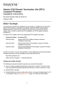
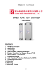
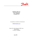
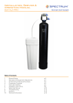
WSHP-DS-6
WSHP-DS-6
March 2000
Water Source
Heat Pump
Water-to-Water
Model WPWD
Introduction
The WPWD product is a heating
and cooling hydronic fluid water-towater heat pump capable of producing water temperature up to
130 F or temperatures down to
25 F. This extended operating
range offers great opportunities in
commercial, residential and industrial applications.
There are many load side applications for which the WPWD is suited.
Typical usages include:
q Hydronic baseboard heating
In the heating mode, the water-towater unit efficiently extracts heat
from a water source (source side)
such as a well, lake, boiler/tower
loop or closed ground loop heat-exchanger, then transfers the heat to
another flow of water (load side).
The amount of heat added to the
load side is greater than the
amount taken from the source side.
The electrical energy supplied to
the compressor is added to the output heat of compression.
q Radiant slab heating
q Space heating or cooling with
Trane fan coils
q Ice and snow removal
q High volume water heating (non
potable)
q Boiler replacement (@130 F)
The Trane water-to-water product
package includes:
q High efficient scroll compressor
q Compressor protection
q Water to refrigerant condensing
coil
q Freeze protection
q Water to refrigerant evaporator
coil
q Expansion valve
q Filter Drier
q Reversing Valve
q Internal desuperheater
(optional)
©An American Standard Company
2
Table
of
Contents
Introduction
2
Features and Benefits
4
Model Number Description
7
General Data
8
Application Considerations
9
Electrical Data
18
Performance Data
19
Dimensional Data
25
Wiring Diagram
28
Accessory Options
30
Mechanical Specifications
31
3
Features
and
Benefits
General
General
WPWD cabinet includes full length
channel stiffeners underneath the
unit.
The water source heat pump model
WPWD (water-to-water) offers a
range of capacities from 2 tons to 6
tons. All units are housed in one
standard compact cabinet.
Cabinet
The cabinet, which allows easy access for installation and service, is
constructed of heavy gauge metal.
The cabinet finish is produced by a
corrosion resistant electrostatic
powder paint coating in the color
“soft dove”.
Heat Exchanger
The water to refrigerant heat exchangers are made of stainless
steel brazed plate. This design provides a larger amount of surface
area for heat exchange between
the water and the refrigerant. (See
Figure 2 for cut-away).
.
The top half of the diagonal cabinet
is removable for access to the internal components by removing two
screws. (See Figure 1).
Figure 2: Brazed plate heat exchanger
Piping
All low-side copper tubing in the refrigeration circuit is insulated to prevent condensation at low entering
liquid temperatures.
Filter Drier
Figure 1: Unit access
A filter drier is provided in each unit
for dehydration and cleaning of the
refrigeration circuit. This feature
adds to the unit life.
Insulation
Expansion Valve
To reduce condensation and compressor noise, the cabinets are insulated with 1/2-inch thick,
neoprene backed, acoustical fiberglass insulation.
As standard, Trane provides a balanced port thermal expansion
valve. This valve precisely meters
the refrigerant flow through the circuitry to achieve the desired heating or cooling over a wide range of
fluid temperatures.
Compressor
The model WPWD contains a high
efficiency scroll compressor for reliable and efficient operation. The
scroll compressor’s unique design
lends itself to having one of the lowest sound levels in the industry.
The compressor is internally isolated and placed on a stiff base plate
designed to further reduce vibration
noise. As an added benefit, the
4
Water Connections
All water connections feature
1-inch brass swivel connectors. Because the connectors are swivel, a
back-up wrench is not necessary
when tightening.
Features
and
Benefits
Controls
24 Volt Controls
All electrical controls and safety devices are factory wired, tested, and
mounted in the unit. The control
package includes:
50 VA Transformer
Lockout
Relay
24 VAC Contactor
q Compressor contactor
Ground
q 24 Volt transformer
q Lockout relay
q Compressor run capacitor (1phase units only)
Compressor
Run Capacitor
q Reversing valve coil (For heat
pump only)
High Voltage
Low Voltage
q Fuse (for desuperheater)
2 Amp Fuse
(for use with
desuperheater
option)
A terminal strip with 1/4” fork connections will be provided for field
thermostat control wiring. (See Figure 3).
10 Pole Terminal
Strip
Safety Devices
Each Trane water-to-water unit contains safety devices to prevent compressor damage. These include:
q Low pressure switch
q High pressure switch
q Temperature sensor (freezestat)
q Internal overload protection
Low Pressure Switch
The low pressure switch prevents
compressor operation under low
charge or in excessive loss of
charge situations. This device is set
to activate at refrigerant pressures
of 35 psig when a 35 F low temperature detection thermostat is applied. An optional 7 psig pressure
switch is available when using a 20
F temperature low temperature detection thermostat.
Thermostat
Low Voltage
Low Temperature
Detection Thermostat
The low water temperature detection thermostat is provided to protect the water-to-refrigerant heat
exchanger from freezing. This device prevents compressor operation if leaving water temperature is
below 35 F. An optional 20 F temperature thermostat may be applied
for low water temperatures where
an appropriate antifreeze solution is
used.
Figure 3: Controls
Lockout Relay
When the safety controls are activated to prevent compressor short
cycling, the lockout relay (circuit)
can be reset at the thermostat, or by
cycling power to the unit.
Thermostat Hook-up
Low voltage and high voltage
knockouts are provided in the top
half of the unit. All control wiring to
the unit should be 24 Volt.
(See Figure 4 for termination
points).
High Pressure Switch
For internal overload protection,
Trane provides a high pressure
switch. This de-energizes the compressor when discharge pressure
become excessive.
24V Power
Compressor
Reversing Valve
(energized in clg)
Figure 4: Typical thermostat termination points
5
Features
and
Benefits
Heat
Recovery
Desuperheater Option
The desuperheater option is a heat
recovery system packaged within
the water-to-water unit. This option
captures heat energy from the heat
pump for considerable cost savings
all year. Since it is active in either
operating mode, it can provide hot
water at a reduced cost while in
heating or virtually free hot water
while in cooling.
Standard equipment includes:
The unit employs a circulating pump
to move water through a double wall
heat exchanger. It then returns the
heated water to the water tank. This
water is heated by superheated refrigerant discharge gas from the
compressor. This heat energy can
now be utilized as a cost savings in
water heating.
Circulating Pump
The pump is a circular, single stage
open system pump. Its specifications include:
q 1/25 HP (horsepower)
q Desuperheater (heat
exchanger)
q 230 Volt / 60 Hertz / 1 phase
q Circulating pump
q 90 Watts
q Entering water temperature
detector (125 F stops pump)
q .40 Amps
q Discharge refrigerant
temperature detector (145 F
starts pump)
q Fuse
q Water heater hook-up kit
q 2865 rpm (revolutions per
minute)
q 2 MF (microfarad) / 400 Volt
capacitor
The pump contains a minimum fluid
temperature rating of 50 F, a maximum fluid temperature (open system) of 140 F, and a maximum
working pressure of 145 psi.
Hot water
(Supply)
Isolation
Valves
(by others)
from Desuperheater
to Desuperheater
Desuper-out
Desuper-in
Water heater
hook-up kit with
drain valve
6
Cold water
(Supply)
Model Number
Description
1
5
10
15
Digit 11: Freeze Protection
(source side)
1 = Brazed Plate Heat Exchanger
with 35 F (1.67 C) Freezestat
2 = Brazed Plate Heat Exchanger
with 20 F (-6.67 C) Freezestat
Digits 1 & 2: Product Type
WP = Trane Commercial Water
Source Heat Pump
Digit 3: Product Configuration
W = Water-to-Water
Digit 4: Development Sequence D
Digit 12: Freeze Protection
(load side)
1 = Brazed Plate Heat Exchanger
with 35 F (1.67 C) Freezestat
2 = Brazed Plate Heat Exchanger
with 20 F (-6.67 C) Freezestat
Digits 5-7: Unit Nominal Capacity
024 = 24.0 MBh
036 = 36.0 MBh
042 = 42.0 MBh
048 = 48.0 MBh
060 = 60.0 MBh
072 = 72.0 MBh
Digit 13: Desuperheater Option
0 = No Desuperheater
1 = With Desuperheater
Digit 14: Open
0 = Open Digit
Digit 8: Voltage / Hertz / Phase
1 = 208-230/60/1
3 = 208-230/60/3
4 = 460/60/3
5 = 575/60/3
6 = 220-240/50/1
7 = 265/60/1
9 = 380-415/50/3
Digit 15: Open
0 = Open Digit
Digit 16: Sticker Option
T = Trane
C = Command-Aire
Digit 9: Unit Arrangement
0 = Water-to-Water
Digit 10: Design Sequence C
7
General
Data
Table G-1: Physical Data (English)
Model: WPWD
Width of cabinet (in)
024
036
042
048
060
072
23
23
23
23
23
23
Width of cabinet and connections (in)
24.8
24.8
24.8
24.8
24.8
24.8
Height (in)
24.3
24.3
24.3
24.3
24.3
24.3
Depth (in)
23.3
23.3
23.3
23.3
23.3
23.3
Compressor
R-22
Type
Refrigerant (lbs)
Scroll
3.25
Scroll
3.375
Scroll
3.50
Scroll
4.00
Scroll
4.25
Scroll
4.25
Approximate Weight
(lbs)
With crate (lbs)
163
183
203
214
244
277
Unit Size
Table G-2: Specifications (English)
Model: WPWD
024
036
042
048
060
072
Source and Load
GPM
4.0
6.0
7.0
7.50
10
10
Source and Load
Ft. Hd.
1.4
3.2
4.4
5.0
9.2
9.2
Cooling
Load EWT 45 F (MBH)
18.24
26.74
31.3
35.55
45.98
51.01
Cooling
Heating
Load EWT 45 F (EER)
Load EWT 100 F (MBH)
15.0
25.38
15.7
33.34
15.7
39.69
15.4
42.87
15.5
57.15
14.9
67.47
Heating
Load EWT 100 F (COP)
3.64
3.62
3.7
3.45
3.62
3.62
Note:
q Source EWT (entering water temperature) is at 75 F
q Unit selection should be based upon extended specifications at lowest or highest expected source and load
EWT (entering water temperature)
q Refer to pages 19-25 for extended performance tables.
8
Application
Considerations
Closed Loop System
Closed loop systems (both ground source
and surface water) provide heat rejection
and heat addition to maintain proper water
source temperatures.
Operating and maintenace cost are low
because an auxillary fossil fuel boiler and
cooling tower are not required to maintain
the loop temperature. The technology has
advanced to the point where many electric
utilities and rural electric cooperatives are
offering incentives for the installation of
geothermal systems. These incentives are
offered because of savings to the utilities
due to reduced peak loads that flatten out
the system demand curve over time.
For ground source geothermal systems,
(See Figure 5), when building cooling Figure 5: Ground source geothermal system
requirements
cause
loop
water
temperatures to rise, heat is dissapated into
the cooler earth through buried polyethylene
pipe heat exchangers. If reversed, heating
demands cause the loop temperature to fall,
enabling the earth to add heat to meet load
requirements.
Where local building codes require water
retention ponds for short term storage of
surface run-off, a ground source surface
water system, (See Figure 6), can be very
cost effective. This system has all the
advantages as the geothermal system in
cooling dominated structures.
Another benefit of the ground source system
is that it is environmentally friendly. The loop
is made of chemically inert, non-polluting
polyethylene pipe. The heat pumps use
HCFC-22 refrigerant, which has a lower
ozone depletion potential than CFC-12.
Because the closed loop system does not
require a heat adder, there are no CO2
emissions. Less electric power consumed
reduces secondary emissions from the
power plant. Therefore, the system offers
advantages not seen by other central
furnace or heat pump systems.
Figure 6: Ground source surface water system
9
Application
Considerations
Open Loop System
Where an existing or proposed well can
provide an ample supply of suitable quality
water, ground water systems may be very
efficient. (See Figure 7)
Operation and benefits are similar to those
for closed loop systems. There are however
several considerations that should be
addressed prior to installation.
q An acceptable way to discharge the
significant volume of used water from
the heat pump should be defined. It may
be necessary to install a recharge well to
return the water to the aquifer.
q Water quality must be acceptable, with
minimal suspended solids. To help
ensure clean water, a straining device
may be required.
Figure 7: Open Loop system
Cooling Tower/Boiler System
A cooling tower/boiler system (see Figure 8)
utilizes a closed heat recovery loop along
with multiple water source heat pumps in a
more conventional manner.
Typically, a boiler is employed to maintain
closed loop temperatures above 60 F and a
cooling tower to maintain closed loop
temperature below 90 F. All the units
function independantly, either by adding
heat, or removing heat from the closed
water loop, making this system more
efficient than air cooled systems.
The cooling tower/boiler system provides a
low installation cost to the owner than other
systems. A good selection for large building
design needs.
Figure 8: Cooling tower/boiler system
10
Application
Considerations
Source Side
vs.
Load Side
Source vs. Load
source side heat exchanger to the
load side heat exchanger.
The model WPWD water-to-water
system contains two water to refrigerant heat exchangers. The two
heat exchangers enable the system
to be divided into a source and load
separation.
The “load side” heat exchanger
takes the place of a DX (direct expansion) air coil. It provides treated
fluid (hot or cold) to a mechanical
device. These mechanical devices
include designs such as radiant slab
heating, hydronic coils, or fresh air
ventilation units.
The “source side” heat exchanger
performs as in a standard water to
air heat pump system. The source is
typically supplied through a cooling
tower, boiler, closed loop, or open
well system. During the refrigeration
cycle, heat is transferred from the
See Figure 9 for a basic schematic
of source side verses load side of a
water-to-water system.
Water-In
(Load Side)
Fluid traveling
TO or FROM a
mechanical device
such as hydronic coil,
concrete slab, or flooring
Water-In
(Source Side)
Refrigeration
Circuit
Fluid traveling
TO or FROM a cooling
tower, boiler, ground
loop or open well
system
Water-Out
(Source Side)
Water-Out
(Load Side)
Figure 9: Source/Load schematic
11
Application
Considerations
Closed Loop
Geothermal
Hydronic Ice
Melting Via
a Water-to-Water
Unit
Geothermal Space
Temperature
Heating / Cooling
Refrigeration
Equipment
(Closed) Ground Loop
Heat Exchanger
Geothermal
Integrated System
The Trane ground source heat
pump is highly efficient in service
station applications.
This integrated system design
takes advantage of the earths
relatively constant temperature
(45 F to 70 F) to space condition
the
building.
In
addition,
appliances such as freezers, ice
makers and a display coolers may
be added to the loop for further
gains in the reduction of consumed
energy.
Cold climates may take an even
greater advantage of the heat
rejected by the stores refrigeration
equipment and space conditioning
heat pumps. This rejected heat
may be used by Trane’s water-towater heat pump(s) to heat water
for a car wash and melt ice off of a
driveway (allowing the car wash to
remain open all winter).
This integrated system also
eliminates thermal short circuiting
between the intakes and the
exhausts of an air cooled
refrigeration system.
12
Typical Benefits
q Annual energy savings means
lower operational costs
q Takes advantage of the earths
constant temperature rather
than high fluctuation of ambient
temperature
q Heat energy rejected from the
space conditioner can be
utilized for ice or snow melting
of a parking lot in colder
climates
q Two to three year estimated
payback on installation costs
Application
Considerations
Fresh Air
Ventilation
Water-Out
(source)
Fresh Air Ventilation
with Water-to-Water Units
Water-Out
(load)
Water-In
(source)
Water-In
(load)
Exhaust
Air Fresh
Air
Geothermal Space
Heating and Cooling
(Closed) Ground
Loop Heat
Exchanger
Water-to-Water
and Fresh Air
Ventilation
Geothermal energy systems take
advantage of the fact that
subsurface earth temperatures are
constant year-round, which makes
the earth an ideal heat source and
heat sink for heat pumps.
The above design goes further than
just space heating and cooling.
Fresh air ventilation is achieved by
using Trane water-to-water units
teamed with a hydronic outside air
unit, and exhaust air unit to meet
total building requirements.
In the cooling season, the
evaporator water from the heat
pumps is circulated through a
hydronic coil in the makeup air unit
to provide cooling and
dehumidification. The condenser
water is used to provide reheat
energy to temper the ventilated air
in accordance with the building
needs. After leaving the reheat
hydronic coil, the condenser water
is then returned to the building loop
for further heat rejection.
In heating, the water-to-water units
switch to hot water generation. The
water for ventilation air tempering
first circulates through the hydronic
coil to the exhaust air unit to pick
up heat from the building exhaust
airstream. The water then
circulates through the water-towater heat pumps for further heat
introduction before being used by
13
the makeup air unit hydronic coil to
heat the makeup air to maintain
building requirements. This
ventilation system incorporates its
own constant volume pumps to pull
system water off the loop and
return it. There is no need for
additional heat injection using
boilers for this system. (See Page
14 for mechanical example).
Typical Benefits
q Annual energy savings means
lower energy costs
q Building comfort and climate
control
Application
Considerations
EXHAUST
AIR
Fresh Air
Ventilation
Mechanical
OUTSIDE
AIR
HOT WATER
COIL
AIR
HANDLER
EXHAUST AIR
TO HEAT PUMPS
EXHAUST AIR
FROM TOILET RMS
AIR
HANDLER
EXP TANK
AUTOMATIC
AIR VENT
HAND
PUMP
WPWD
WPWD
WPWD
WPWD
BALL VA
SUPPLY
RETURN
14
DRAIN VA
PRESSURE
RELIEF VA
Application
Considerations
Central
Pumping
System
6
7
1
5
2
4
General
A central pumping system involves
a single pump design usually located within a basement or mechanical
room to fulfill pumping requirements
for the entire building system. With
a central pumping system, an auxiliary pump is typically applied to
lessen the likelihood of system
down-time if the main pump malfunctions.
(See Figure 10 for unit installation of
a central pumping system).
3
Figure 10: Central pumping system installation
minal devices with 45 F or
Central Pump
120 F fluid.
Application
The sound attenuation pad
should be slightly oversized for
Ball valves should be installed
unit. This field supplied product
in the supply and return lines
is recommended for sound
for unit isolation and unit water
absorption of unit.
flow rate balancing (if an automatic flow device is not
The low voltage control conselected). This connection,
nection provided on the unit is
along with hoses, are also reclarge enough for attaching conommended for backflushing
duit.
and chemical cleaning of the
The central systems supply
water to refrigerant heat
and return lines should be
exchanger.
sized to handle the required
Flexible hoses may be used
flow with a minimum pressure
to connect the water supply
drop.
and return lines to the water
Note: Pipe will sweat if low
inlets and outlets. These hoses
temperature water is run
reduce possible vibration
through the supply or return
between the unit and the rigid
lines. Trane recommends that
system.
these lines be insulated to prevent damage from condensaNote: Hoses and or pipes
tion.
should be made of braided
The field supplied line voltage
stainless steel, and sized suitdisconnect should be
ably for the systems water
installed for branch circuit propressure and flow rate.
tection. The unit is supplied
Load side connections are
with an opening for attaching
typically used to supply the terconduit.
Application
Considerations
Well Water
Systems
7
6
Ov
ow
erfl
turn
Re
y
ppl
Su
5
9
8
1
3
4
General
A well water application involves an
open loop water supply. The water
is drawn from an open well or pond
into the unit. A straining device is
required with this application.
Similar to the closed loop design,
an open water supply usually
remains at a constant temperature
year round utilizing maximum
efficiency in unit design.
2
Figure 11: Well water installation
Well Water
Application
See Figure 11 for open well water
installation.
Ball valves should be installed
in the supply and return lines
for unit isolation and unit water
flow rate balancing (if automatic flow device is not
selected). This connection,
along with hoses, are also recommended for backflushing
and chemical cleaning of the
evaporator and the condenser.
Flexible hoses may be used to
connect the water supply and
return lines to the water inlets
and outlets. These hoses
reduce possible vibration
between the unit and the rigid
system.
Note: Hoses and or pipes
should be braided stainless
steel, and sized suitable for the
system’s water pressure and
flow rate.
Load side connections are
used to supply the terminal
device.
16
The sound attenuation pad
should be slightly oversized for
the unit. This field supplied
product is recommended for
sound absorption of unit.
The low voltage control connection provided on the unit is
large enough for attaching conduit.
The expansion tank should be
sized to maintain pressure on
the system.
The line voltage disconnect
should be installed for branch
circuit protection. The unit is
supplied with an opening for
attaching conduit.
The water regulating valve
assembly is used to maintain
refrigerant pressure in refrigerant circuit as the entering water
temperature varies or is cooler
than ideal.
Schrader connections are
factory installed for ease of
attaching the water regulating
valve assembly.
Application
Considerations
Distributed
Pumping
System
8
7
6
1
5
2
4
General
A distributed pumping system contains either a single or dual pump
module connected directly to the
units supply and return source side.
This design requires individual
pump modules specifically sized for
each water source heat pump. Centralized pumping is not required.
3
Figure 12: Distibuted pumping installation
Earth Coupled
Application
See Figure 12 for a distributed
pumping installation.
Ball valves should be installed
in the supply and return lines
for unit isolation.
Flexible hoses may be used
to connect the water supply
and return lines to the water
inlets and outlets. These hoses
reduce possible vibration
between the unit and the rigid
system.
Note: Hoses and or pipes
should be braided stainless
steel, and sized suitable for the
system’s water pressure and
flow rate.
Load side connections are
used to supply the terminal
device.
17
The sound attenuation pad
should be slightly oversized for
the unit. This field supplied
product is recommended for
sound absorption of unit.
The low voltage control connection provided on the unit is
large enough for attaching conduit.
The ground loop pump module is designed for circulating
commercial loops that require
a maximum flow rate of 20
gpm.
The line voltage disconnect
should be installed for branch
circuit protection. The unit is
supplied with an opening for
attaching conduit.
All polyethene pipe in the
closed loop design should be
insulated to eliminate the risk
of sweating.
Electrical
Data
Table E-1: Electrical Data
024
036
Compressor RLA
11.4
15
18.4
Compressor LRA
56
73
95
Minimum Circuit Ampacity
16
21
Max Fuse Size
Aux Pump Amps
25
2.5
30
2.5
Desuperheater Min Cir Ampacity
14.3
Desuperheater Pump RLA
0.4
Model: WPWD
060
072
20.4
28
32.1
109
169
169
25.8
28.6
39
45
40
2.5
45
2.5
60
2.5
70
2.5
18.8
23
25.5
35
40.1
0.4
0.4
0.4
0.4
0.4
Voltage
042
048
208-230/60hz/1phase
Voltage
Compressor RLA
208-230/60hz/3phase
11.4
13.9
-
10.7
20
19.3
Compressor LRA
-
63
77
88
123
137
Minimum Circuit Ampacity
Max Fuse Size
-
15
20
16
25
19.4
30
28
45
27
40
Aux Pump Amps
-
2.5
2.5
2.5
2.5
2.5
Desuperheater Min Cir Ampacity
-
13.4
14.3
17.4
25
24.1
Desuperheater Pump RLA
Voltage
-
0.4
0.4
0.4
Compressor RLA
-
5
5.7
7.1
7.5
10
Compressor LRA
-
31
39
44
49.5
62
Minimum Circuit Ampacity
Max Fuse Size
-
7
15
8
15
10
15
10.5
15
14
20
Aux Pump Amps
-
2.5
2.5
2.5
2.5
2.5
Desuperheater Min Cir Ampacity
-
6.3
7.1
8.9
9.4
12.5
Desuperheater Pump RLA
Voltage
-
0.4
0.4
0.4
Compressor RLA
-
-
-
-
6.4
7.8
Compressor LRA
-
-
-
-
40
50
Minimum Circuit Ampacity
Max Fuse Size
-
-
-
-
9
15
11
15
Aux Pump Amps
Desuperheater Min Cir Ampacity
-
-
-
-
2.5
8
2.5
9.8
Desuperheater Pump RLA
Voltage
-
-
0.4
0.4
Compressor RLA
9.6
14.3
16.4
17.1
-
-
Compressor LRA
47
71
83
98
-
-
Minimum Circuit Ampacity
Max Fuse Size
13.5
20
20
30
23
35
24
35
-
-
Aux Pump Amps
2.5
2.5
2.5
2.5
-
-
Desuperheater Min Cir Ampacity
12
17.9
20.5
21.4
-
-
Desuperheater Pump RLA
0.4
0.4
0.4
0.4
-
-
0.4
0.4
460/60hz/3phase
0.4
0.4
575/60hz/3phase
265/60hz/1phase
18