1
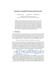
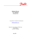
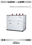
Chapter 4 User Manual
BRAZED PLATE HEAT EXCHANGER
User Manual
CONTENTS
1. Working Principle
2. Application
3. Advantage
4. Specification & BPHE Dimension
5. Design Condition for Copper Brazed PHE
6. Standardized Connections
7. Installation Guide
8. Anti-Freezing Protection Methods for BPHE
9. Soldering Instruction
10. Cleaning
11. Warning
12. Warranty Terms
4-1
1. Working Principle
Kaori’s Brazed Plate Heat Exchanger (BPHE) consists of chevron plates
of acid-resistant stainless steel. Every other plate is reversed so the ridges
of the herringbone pattern intersect one another on adjacent plates
forming a lattice on contact points. When these points are vacuum brazed
together, two separate systems of channels for two media flow in
counter-current are formed. The lattice structure causes vigorous
turbulence, thus ensuring maximum heat transfer.
The BPHE is a highly efficient, corrosion-resistant, and pressure-resistant
heat exchanger. The standard BPHE is designed to meet 30 bar, 200℃, with
the largest model capable of handling a maximum flow capacity of 900
liter/min.
4-2
2. Application
Kaori BPHE can be used for various mediums such as:
- All type of refrigerants
- Nickel brazed models used for Ammonia
- Organic solvents
- Water
- Oil
- Various brine solutions (glycol mixtures, CaCl2, alcohols etc)
Kaori BPHE can be used in:
- Heat pumps
- Industrial chiller; plastic machines, welding machines, hydraulic
presses (oil), and compressor oil cooling
- Air conditioning
- Refrigeration
- Air dryer
- Water cooler; drinking water or process water for various industries
- Temperature holding for storage tanks
- Heat recovery including heat recycling from hot steam
- Indoor heating including floor heating
Refrigerant applications, BPHE function as:
- Evaporators
- Condensers
- Super-heaters for gas
- Desuper-heaters for gas
- Subcoolers for condensate
- Economizers
- Intercoolers
- Oil coolers
3. Advantages
Kaori BPHE provides many advantages such as:
- Highly thermal efficiency
- Compact in size and light weight
- High allowable working pressure
- High thermal resistances and high operating temperature
- Lower cost for the same performances
- Lower pressure drop and high corrosion resistance
- No gaskets required therefore no leakages
- Easy installation, easy replacement with less maintenance
- Durability
4-3
4.Specification & BPHE Dimension
Type
L1
L2
W1 W2
Weight
mm mm mm mm
Kg
205 172 73 42 0.81+0.04(N-1)
Thickness
(H)mm
Area
Volume
M2/plate Liter/Channel
Max NO.
of plate
8+2.27(N-1)
0.012
0.025
60
K025F×A 206.2 172 74.2 40
0.3+0.044(N-2) 11+2.25(N-2)
0.012
0.025
60
K025F×B 206.2 172 74.2 42
0.3+0.044(N-2) 11+2.25(N-2)
0.012
0.025
60
K025F
40
0.8+0.05N
10+2.25N
0.0117
0.025
60
K030E 194.5 154 80.5 40
0.3+0.045N
7+2.25N
0.0117
0.025
60
K030
194
154
80
K030S
194
154
80
40
1.2+0.05N
12+2.25N
0.0117
0.025
60
K040
311
278
73
40
0.84+0.07N
10+2.3N
0.01946
0.040
60
K040E
311
278
73
40
0.68+0.07N
9+2.3N
0.01946
0.040
60
K040S
311
278
73
40
1.3+0.07N
12+2.3N
0.01946
0.040
60
K050
306
250 106
50
1.5+0.135N
10+2.4N
0.0255
0.055
100
K050S
306
250 106
50
2.2+0.15N
12+2.4N
0.0255
0.055
100
K070
304
250 124
70
1.6+0.15N
10+2.4N
0.03
0.065
100
K070S
304
250 124
70
2.5+0.17N
12+2.4N
0.03
0.065
120
K095
522
466 106
50
3.1+0.22N
10+2.4N
0.0475
0.095
100
K095S
522
466 106
50
5.0+0.24N
13+2.4N
0.0475
0.095
100
K105
504
444 124
64
3.5+0.24N
10+2.4N
0.0533
0.107
120
K105S
504
444 124
64
6.2+0.27N
13+2.4N
0.0533
0.107
120
K200H
613
519 186
92
7.12+0.41N
14+2.4N
0.09446
0.206
160
K200L
613
519 186
92
7.12+0.41N
14+2.4N
0.09446
0.206
160
K200M
613
519 186
92
7.12+0.41N
14+2.4N
0.09446
0.206
160
K200S
613
519 186
92
11.88+0.47N
17+2.4N
0.09446
0.206
160
K200E
613
519 186
92
1.84+0.4N
11.5+2.4N
0.09446
0.206
160
K205
528
456 246 174
7.2+0.52N
11.5+2.4N
0.1099
0.232
200
K205S
528
456 246 174
12.9+0.59N
14.5+2.4N
0.1099
0.232
190
K210
527
430 245 148
8.5+0.490N
11+2.85N
0.1036
0.289
200
K215
529
449 247 167
7.2+0.52N
13+2.4N
0.11
0.22
200
K215D
529
449 247 167
7.2+0.52N
13+2.4N
0.11
0.22
200
K215S
529
449 247 167
13.1+0.52N
16+2.4N
0.11
0.22
200
K040C
314
275
76
40
1.98+0.137N
13+2.0N
0.01925
0.0295
60
K040C×A 314
275
76
40
2.02+0.124N
13+2.0N
0.01925
0.0295
60
K040C×B 314
275
76
40
2.06+0.124N
13+2.0N
0.01925
0.0295
60
524
466 108
50
5.0+0.37N
13.2+2.16N
0.0475
0.071
120
K095C×A 524
466 108
50
5.1+0.32N
13.2+2.16N
0.0475
0.071
120
K095C×B 524
466 108
50
5.2+0.32N
13.2+2.16N
0.0475
0.071
120
K095C
4-4
5.Design Condition for Copper Brazed PHE
Type
K025F×A,K025F×B
K030E,K040E,K200E
K210
Max. working
Pressure
Test Pressure
Max. working
Temperature
10 Bar
15 Bar
–160~+200℃
16 Bar
23 Bar
–160~+200℃
30 Bar
43 Bar
–160~+200℃
30 Bar
43 Bar
–160~+200℃
45 Bar
65 Bar
–160~+200℃
Max. working
Pressure
Test Pressure
Max. working
Temperature
K025F,K030,K040
K050,K070,K095
K105,K200H,K200L
K200M,K205,K215
K215D
K215S
K030S,K040S,K050S
K070S,K095S,K105S
K200S,K205S
Type
Side 1
Side 2
Side 1
Side 2
K040C,K095C
140 Bar
30 Bar
200 Bar
43 Bar
–160~+200℃
K040C×A,K095C×A
70 Bar
30 Bar
100 Bar
43 Bar
–160~+200℃
K095C×B,K095C×B
100 Bar
30 Bar
143 Bar
43 Bar
–160~+200℃
4-5
6.Standardized Connections
*Connections for fluid applications are threaded connectors.
*Connections for refrigerant units are soldered/sweat connectors.
Threaded Connections
Type
PT/NPT/GB – Male
1/2"
K025F
K030
K040
K050
K070
K095
K105
K200
K205
K210
K215
※
※
※
※
※
※
※
3/4"
※
※
※
※
※
※
1"
※
※
※
※
※
※
1-1/4" 1-1/2"
2"
PT/NPT/G – Female
2-1/2"
※
※
※
※
※
※
※
※
※
※
※
※
※
※
※
※
※
3"
1/2"
※
※
※
※
※
※
※
※
※
※
※
3/4"
※
※
※
※
※
※
1"
※
※
※
※
※
※
1-1/4" 1-1/2”
※
※
※
※
※
※
2"
2-1/2"
※
※
※
Soldered Connections
Type
K025F
K030
K040
K050
K070
K095
K105
K200
K205
K210
K215
1/4”
ψ6.60
㎜
※
※
※
※
※
※
※
3/8”
1/2”
5/8”
3/4”
7/8”
1”
1-1/8” 1-3/8” 1-5/8” 2-1/8”
ψ9.73 ψ12.90 ψ16.15 ψ19.25 ψ22.36 ψ25.60 ψ28.80 ψ35.25 ψ41.50 ψ54.30
㎜
㎜
㎜
㎜
㎜
㎜
㎜
㎜
㎜
㎜
※
※
※
※
※
※
※
※
※
※
※
※
※
※
※
※
※
※
※
※
※
※
※
※
※
※
※
※
※
※
※
※
※
※
※
※
※
※
※
※
※
※
※
※
※
※
※
※
※
※
※
※
※
※
※
※
※
※
※
※
※
※
Threaded Connections
※
※
※
※
※
※
※
※
Soldered Connections
4-6
※
7. Installation Guide
Illustration of 1:General purpose of BPHE
2:Types of fluid applied
3:Arrangements of fluids directions
Application
Fluid 1
Fluid 2
Evaporator
(single refrigerant)
Evaporator
(dual refrigerant)
Refrigerant
A2→A1
Refrigerant 1
A2→A1
Refrigerant
A1→A2
Cold water
A2→A1
Cooling water
A2→A1
Refrigerant
A2→A1
Oil
A2→A1
Chiller water
B1→B2
Chiller water
B1→B2
Cooling water
B2→B1
Hot water
B1→B2
Oil
B1→B2
Condenser
Heating,Cooling
Oil cooler
Air Dryer
(Refrigerant)
Air&Oil cooling
(Air compressor)
Fluid 3
Refrigerant 2
C2→C1
Air
D2→(D1)→(B1) →B2→Separator→C1→C2
Cooling water
D2→(D1)→(B1) →B2
Air
C1→C2
※Always install your BPHE vertically especially for a refrigerant system.
This is done to secure the BPHE and keep minimum amount of water
below the connector.
※In order to achieve high thermal efficiency and high heat transfer rates,
BPHE has to be installed in a counter flow direction.
4-7
※When BPHE works as an Evaporator, the two-phased (liquid an gas)
refrigerant enters the evaporator at the bottom left connector and the
single-phased (gas) refrigerant leaves the evaporator from the top left
connector after the heat transfer process. The water enters at the top
right connector and leaves from the bottom right. In the case of
evaporator, heat is transferred from water to refrigerant and both fluids
are in counter flow direction.
※When BPHE works as a condenser, the single-phased (gas)
refrigerant enters the condenser at top left connector and the
single-phased (liquid) refrigerant leaves the condenser from the
bottom left connector. The water enters the condenser at bottom right
and leaves the condenser from top right. In the case of condenser,
heat is transferred from refrigerant to water and both fluids are in
counter flow direction.
※Mounting suggestions: There are four different ways to mount the
BPHE:
(a) Bottom support (b) Sheet metal bracket, (c) Crossbar& bolts, (d) Stud
bolts
-All items should be supported independently.
-Do not apply excessive forces to the fittings.
-Except for small sized K030 model, our BPHE cannot be fastened
directly to the fittings/piping.
-Using flexible hoses or vibration dampers to reduce pulsation, shock or
vibrations that are caused by the operating system.
4-8
8. Anti-Freezing Protection Methods for BPHE:
Any formation of freezing or icing will damage BPHE and the
refrigeration system. The following methods will prevent BPHE from
freezing:
-Use brine (e.g. glycol) when evaporation temperature is close to the
freezing point.
-Low working pressure will cause low evaporation temperature. If the
evaporation temperature is below 0℃, it will cause water to freeze.
Since the bottom portion has the lowest temperature, it is the most
likely spot for the BPHE to crack.
-To start the refrigeration system, always start the water pump for a few
minutes and then start the compressor. To stop the system, always stop
the compressor first and then stop the water pump.
(1) Low Pressure Cut-off Switch (LP)
A low-pressure cut-off switch should be installed with properly set
values. When the actual evaporation pressure is lower than the
setting value, the compressor will be cut off automatically.
(2) Low Temperature Thermostat (LT)
The function of the thermostat is to prevent evaporation temperature
going under 0℃. If evaporation temperature is always above 0℃; then
water has no chance to freeze and expand.
(3) Water Temperature Sensor
Installation of an anti-freezing temperature sensor near the water
outlet is another method to prevent the water from freezing. The
setting temperature is suggested at 4℃ for buffering purposes.
(4) Water Flow Switch
Installation of a water flow switch in the water circuit can prevent
possible BPHE freezing up due to low water flow rate. Usually, low
water flow rate may be caused by malfunction of water pump,
leaking pipes, pipe blockage due to pipe contamination or dirty
filter.
4-9
9. Soldering Instruction
Cleaning and degreasing the surface of copper pipes and PHE
connectors before soldering is important. To avoid the inside of copper
pipes and BPHE from oxidation, protect the inside with N2-gas. Place the
BPHE on a flat surface and wrap a wet rag around the connectors to
protect the BPHE from excessive heating. Use a 40~45% silver alloy
soldering rod to weld the copper pipe into the connector at a maximum
temperature of 800℃. After soldering, clean and dry the connection and
BPHE.
10. Cleaning
Cleaning of fouled plate heat exchangers by back flushing will remove
most of the soft debris that is blocked the inside. The solution used for
back flushing shall be weak acids with concentration less than 5%; one
example the citric acid. If the acidity is too high, the copper and stainless
steel inside the PHE may be etched or corroded. Before restarting the
system, flush the plate heat exchanger with large amounts of fresh water
to purge any remaining acid solution.
11. Warning
-Fluid that is explosive, extremely flammable, highly toxic, highly
corrosive, hazardous in nature cannot be used with the BPHE.
Examples are nitric acid, sulfuric acid, ammonia (for copper models)etc.
-When unknown quality of water is applied to BPHE, filter and strainer
should be placed at the water inlet of BPHE to filter out the dirt or large
particles. Mesh size of around 20 is suitable for most cases. Blockage
of evaporator due to dirt or large particles will reduce the flow rate of
water which might cause freezing effect and consequently damage the
integrity of the BPHE.
-Chlorinated water, seawater, etc. are not suitable for BPHE due to their
corrosive nature on regular stainless steel and copper. For example,
swimming pool water.
4-10
-Solution which applied to BPHE shall have PH values ranging between
6 ~ 8.
-Ground water with high sulfuric compound, sulfuric acid, low PH value,
may cause gradual copper corrosion and damage the BPHE in a few
years.
-Rubber strips always cover the bottom edge of the BPHE in order to
protect the hand and wrist against the sharp metal edges. If the rubber
strip is not a required part of your order, be careful of the sharp metal
edge.
-When moving the BPHE, always wear gloves and pay attention to the
sharp edges around the bottom of BPHE. Our BPHE can come without
the rubber protective strip at your request.
12. Warranty Terms
-Free replacement of the defective unit if the defect is found to be
caused by manufacturing material or manufacturing workmanship.
-Warranty period is standard 12 months after delivery date or according
to the period listed on the official proforma invoice.
-Exceptions are:
(1) The failure or malfunction of BPHE is caused by improper or negligent
usage of BPHE.
(2) Malfunctions from freezing or icing, flood, fire, any natural disaster or
accident.
(3) Damages caused by improper or faulty installation or product
exposed to corrosive elements harmful to the structure.
4-11
13. Label and Marking
The following nameplate is an example of KAORI BPHE
K205 type:
Model name K205-26-26D-S9 will be shown on the label attached.
For tracking purposes, a serial no. 09052121019-26-26D-S9 will be
carved on the front cover plate and below the two upper connectors of
the BPHE.
4-12