1
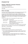
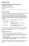
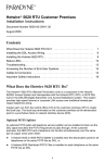
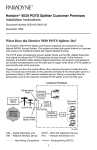
TM Hotwire 5216 Remote Termination Unit (RTU) Customer Premises Installation Instructions Document Number 5216-A2-GN10-10 February 1998 Before You Begin An optional POTS (Plain Old Telephone Service) splitter is available for the 5216 RTU. When a POTS splitter is installed, the telephone and 5216 RADSL (Rate Adaptive Digital Subscriber Line) RTU can function at the same time over the same pair of copper wires. In order to confirm the RTU installation, the POTS splitter should be installed first. To install a POTS splitter, refer to the appropriate POTS splitter document: Document Number Document Title 5030-A2-GN10 Hotwire 5030 POTS Splitter Customer Premises Installation Instructions 5034-A2-GN10 Hotwire 5034 Indoor POTS Splitter Customer Premises Installation Instructions 5038-A2-GN10 Hotwire 5038 Distibuted POTS Splitter Customer Premises Installation Instructions Contact your sales or service representative to order additional product documentation. Paradyne documents are also available on the World Wide Web at: http://www.paradyne.com Select Service & Support → Technical Manuals Wiring and Cables Needed The following wiring and standard connectors are used with this product: - New or existing unshielded twisted-pair wiring (CAT3 or better). The CAT3 wiring must meet EIA/TIA-568 specifications with 24 AWG (.5 mm) or 26 AWG (.4 mm). - Standard RJ11 wall jack. - Standard Ethernet crossover cable with an 8-pin, non-keyed modular plug for a PC or workstation. Refer to Installing the RTU, page 9, for Ethernet cable details. 1 Package Checklist Verify that your package contains the following: - Model 5216 Remote Termination Unit (RTU) - DSL interface cable with RJ11 modular plugs - Power cord with power transformer - Two ferrite chokes - Warranty card Refer to Cables & Connectors, page 13, for standard pin numbers. What Does the Hotwire RTU Do? The 5216 RTU is a component in the DSL Access System. This system provides high-speed Internet or corporate LAN access over traditional twisted-pair copper telephone wiring. DSL Access with a POTS Splitter Copper pairs run from the central office (CO) to the customer premises (CP) to create the local loop. The local loop terminates on the customer premises at the demarcation point in a punchdown block or network interface device (NID). 2 When a POTS splitter is used at both ends of the local loop, wiring is connected: H From the demarcation point to the CP POTS splitter, and H From the demarcation point to the DSL jack. Customer Premises (CP) Demarcation Point POTS Central Office (CO) Local Loop Network Service Provider (NSP) Punchdown Block or NID CP POTS Splitter DSL DSL Jack RTU Ethernet Crossover Cable End-user System 97-15608 DSL - Digital Subscriber Line NID - Network Interface Device POTS - Plain Old Telephone Service RTU - Remote Termination Unit New Wiring Connections Existing Wiring (POTS) NOTES: — End-user system is used to represent any PC on the customer premises with an Ethernet connection and DSL-based service. — Network Service Provider (NSP) is used to represent any Internet Service Provider (ISP) or internal LAN administrator. 3 DSL Access without a POTS Splitter When the 5216 RTU is installed without a POTS splitter, a second telephone wiring pair is needed for DSL access. Customer Premises (CP) Demarcation Point POTS Central Office (CO) Local Loop Network Service Provider (NSP) Punchdown Block or NID DSL DSL Jack RTU Ethernet Crossover Cable End-user System 97-15609 DSL - Digital Subscriber Line NID - Network Interface Device POTS - Plain Old Telephone Service RTU - Remote Termination Unit New Wiring Connections Existing Wiring (POTS) 4 Installing the DSL Access Wiring The local loop terminates at the punchdown block or NID. Wiring must be connected from the customer premises side of the punchdown block or the NID to the DSL jack. Typically, the punchdown block is installed in commercial locations and the NID is installed in residential locations. " Procedure 1. Access the punchdown block or NID. Disconnect the DSL access pair from the local loop. ! WARNING: Do not continue unless the DSL access line from the local loop has been disconnected at the NID or punchdown block. Refer to Important Safety Instructions, page 16. A punchdown block is used without a POTS splitter in the following example. Punchdown Block Customer Premises Demarcation Point DSL Access from Local Loop Wiring to DSL Jack Bridge Clip A B C D 97-15348 5 Green (T1) and red (R1) are the standard wiring colors used in the next two illustrations. In the following example, a NID is used without a POTS splitter. It includes an existing POTS line and a second pair installed for DSL access. The POTS pair for the existing POTS line wiring does not need to be disconnected unless a POTS splitter is going to be installed. Telephone Network Interface Device (NID) Customer Premises Demarcation Point Tip T1 (Green) DSL Pair POTS Pair Ring R1 (Red) DSL/POTS Access from Local Loop Existing POTS Wiring to Telephone Ground 6 97-15439-01 2. Locate the DSL pair of T1/R1 connectors on the customer premises side of the NID or punchdown block. Attach the wiring that will be connected to the DSL jack. Tighten both terminal screws with a flat-blade screwdriver. Telephone Network Interface Device (NID) Customer Premises Demarcation Point Tip T1 (Green) DSL Pair POTS Pair Ring R1 (Red) Wiring to DSL Jack Existing POTS Wiring to Telephone Ground DSL/POTS Access from Local Loop 97-15438-01 7 DSL Jack Installation The 5216 RTU connects to the local loop via wiring from the demarcation point to an RJ11 wall jack. The DSL twisted-pair wiring from the local loop terminates at a new or existing wall jack. It may be necessary to install a standard single RJ11 jack or replace a single jack with a double RJ11 jack. The RJ11 6-pin jack uses the center two pins. For pin assignments, refer to Cables & Connectors, page 13. Customer Premises Demarcation Point DSL Twisted-pair Wiring DSL RJ11 Jack Central Office POTS/DSL Local Loop RTU Punchdown Block or NID 97-15343-02 " Procedure 1. Wiring can be run from the punchdown block or NID to a new or existing wall jack. Match the pair colors on both ends. 2. Label the DSL jack. R J 11 W all J ac k or 97-15300a 3. At the demarcation point, reconnect the DSL access wire pair to the local loop. Refer to Installing the DSL Access Wiring, page 5. Tighten both terminal screws with a flat-blade screwdriver. 8 Installing the RTU Place the 5216 RTU on a flat surface with clearance for the rear connectors. " Procedure 1. Use the RJ11 6-pin cable for the DSL connection. Insert one end of the cable into the jack labeled DSL. Insert the other end into the wall jack labeled DSL. Hotwire RTU POWE R ETHER DSL Jack NET DSL 97-15300-01 2. Use an 8-pin Ethernet crossover cable for the Ethernet connection. Insert one end of the cable into the jack labeled ETHERNET. Connect the other end to a PC with an Ethernet Network Interface Card (NIC). Hotwire RTU Ethernet Line P OW E PC with Ethernet Network Interface Card R ETHER NET DSL Ethernet Cable 97-15303b For RTU cable pin assignments, refer to Cables & Connectors, page 13. 9 3. Place the large ferrite choke on the Ethernet cable as closely as possible to the RTU. Pass the Ethernet cable through the ferrite choke twice, creating a loop as shown. 496-14952 4. Close the two halves around the cable and snap the ferrite choke shut. Press down on the plastic latch to secure the ferrite choke in place around the cable. Hotwire RTU Ethernet Line P OW E R ETHER NET Ferrite Choke DSL 97-15303c 5. Insert the power cord’s round end into the jack labeled POWER. Attach the ferrite choke on the power cord as closely as possible to the RTU. Pass the power cable through the ferrite choke twice, creating a loop as shown. Hotwire RTU Power Jack P OW E Ferrite Choke R ETHER NET DSL 98-15817 10 6. Close the two halves around the cable and snap the ferrite choke shut. Press down on the plastic latch to secure the ferrite choke in place around the cable. 7. Plug the transformer into an AC outlet. The RTU hardware installation is now complete. When the power cord is installed, the RTU goes through a power-on self-test. Power-On When power is applied, the RTU performs self-diagnostics and the PWR LED is on. The self-diagnostics includes a power-on self-test. During the power-on self-test, all of the LEDs turn on for one second. Power – green Alarm – red Test – yellow Digital Subscriber Line – green Ethernet Link – green PWR ALM TST DSL ETHERNET 5216 TM 97-15607 Refer to Troubleshooting, page 12, for LED indications requiring action. Status LEDs All of the LEDs turn on and off during the power-on self-test. After a successful self-test, the LEDs should appear as indicated in BOLD in the Condition column below. LED Condition Status PWR ON RTU has power. ALM OFF No active alarms. ON An alarm condition exists. OFF No active tests. ON The TST LED is on during the power-on self-test and during a test initiated by the NSP. TST 11 LED Condition Status DSL Blinking RTU is establishing the DSL link. The LED blinks on and off about five times per second. ON The DSL link is now active and ready to transmit and receive data. OFF The DSL link has not been established. ETHERNET ON The Ethernet 10BaseT connection to the end-user system is active. OFF No Ethernet 10BaseT device is detected. Firmware Download The firmware download feature is available via the DSL link or the Ethernet port. During a firmware download, the following LEDs are on: H ALM H TST H ETHERNET H PWR Troubleshooting LED Symptom Action All LEDs are on. The RTU is not functional. Contact the NSP. ALM LED remains on. The power-on self-test may have failed. Unplug the unit and reapply power. If the alarm light is still on, contact the NSP. ALM and TST LEDs remain on. Refer to Firmware Download. If the LEDs remain on after five minutes, contact the NSP. DSL LED is off. Verify that the DSL cable is securely installed on both ends. If the RTU is not in firmware download mode, unplug the RTU and reapply power. If problem continues, contact the NSP. DSL LED continues to blink after the power-on self-test. The RTU is attempting to establish the DSL link. If the DSL LED continues to blink for more than five minutes, contact the NSP. DSL LED is on and there is no data transmission. The DSL link has been established but there is no data transmission. First, verify the Ethernet connection. If the problem persists, contact the NSP. 12 LED Symptom Action DSL and Ethernet LEDs are on and there is no data transmission. The DSL link and the Ethernet link have been established. If the problem continues, contact the NSP. Ethernet LED is off. Verify that the Ethernet 10BaseT cable is securely installed at both ends, and that a PC is connected and powered on. Verify that the correct crossover cable is installed. Refer to Cables & Connectors, page 13. PWR LED is off. Check that the power cord is securely installed on both ends. If no LEDs are on, the power supply may be defective. Try a different outlet to test the power supply. If problem persists, contact the NSP. If other LEDs are on, the PWR light may be burned out. Unplug the unit and reapply power; watch all LEDs during the power-on self-test to verify that the PWR LED is functioning. TST LED is on. A test initiated by the NSP may be active. Wait five minutes. If the TST LED does not go off, contact the NSP. Cables & Connectors Obtain standard twisted-pair CAT3 or better cables. This section is reference information. H The DSL interface connector uses a 6-pin, non-keyed modular plug. RJ11 6-Pin Connector D S L L in e Pin # Function 1&2 Not used 3 DSL Ring 4 DSL Tip 5&6 Not used 6-P in R J11 P lug P in #6 P in #1 97-15304 13 H The Ethernet interface crossover cable connector uses an 8-pin, non-keyed modular plug. E t h er n et C ab le 8 -P in P lu g P in # 8 P in #1 97-15305 8-P in E t h er n et C r o s s o v er C ab le F u n c t io n P in # P in # F u n c t io n 10B aseT T X D + 1 1 10B aseT T X D + 10B aseT T X D 2 2 10B aseT T X D 10B aseT R X D + 3 3 10B aseT R X D + N ot U sed 4 4 N ot U sed N ot U sed 5 5 N ot U sed 10B aseT R X D 6 6 10B aseT R X D N ot U sed 7 7 N ot U sed N ot U sed 8 8 N ot U sed 97-15316 14 Model 5216 RTU Technical Specifications Item Specification* Height x Width x Depth 1.35″ x 6.00″ x 8.75″ (3.43 cm x 15.35 cm x 22.23 cm) Weight 1 lb. 1 oz. (0.48 kg) Power Input: Class 2 Transformer normal service input voltage range 100 Vac, 50 Hz; 120 Vac, 60 Hz; or 230 Vac, 50/60 Hz Output: 15 Vdc nominal (+10%), minimum 0.6A Approvals FCC Part 15 Class B Subpart B digital device CISPR 22 Class B Safety Certifications Refer to equipment’s label for approvals on product. Physical Environment Operating temperature 32° F to 104° F ( 0° C to 40° C ) Storage temperature – 4° F to 158° F ( –20° C to 70° C ) Relative humidity 5% to 95% ( noncondensing ) Shock and vibration Withstands normal shipping and handling Heat Dissipation 40.9 Btu/hr. (max.) at nominal input voltage Interface Connectors DSL Interface RJ11 6-pin Ethernet Type II Frame 10BaseT 8-pin * Technical Specifications subject to change without notification. 15 Important Safety Instructions 1. Read and follow all warning notices and instructions marked on the product or included in the manual. 2. Slots and openings in the cabinet are provided for ventilation. To ensure reliable operation of the product and to protect it from overheating, these slots and openings must not be blocked or covered. 3. Do not allow anything to rest on the power cord and do not locate the product where persons will walk on the power cord. 4. Do not attempt to service this product yourself, as opening or removing covers may expose you to dangerous high voltage points or other risks. Refer all servicing to qualified service personnel. 5. General purpose cables are used with this product for connection to the network. Special cables, which may be required by the regulatory inspection authority for the installation site, are the responsibility of the customer. Use a UL Listed, CSA certified, minimum No. 24 AWG line cord for connection to the Digital Subscriber Line (DSL) network. 6. When installed in the final configuration, the product must comply with the applicable Safety Standards and regulatory requirements of the country in which it is installed. If necessary, consult with the appropriate regulatory agencies and inspection authorities to ensure compliance. 7. A rare phenomenon can create a voltage potential between the earth grounds of two or more buildings. If products installed in separate buildings are interconnected, the voltage potential may cause a hazardous condition. Consult a qualified electrical consultant to determine whether or not this phenomenon exists and, if necessary, implement corrective action prior to interconnecting the products. 8. Input power to this product must be provided by one of the following: (1) a UL Listed/CSA certified power source with a Class 2 or Limited Power Source (LPS) output for use in North America, or (2) a certified transformer, with a Safety Extra Low Voltage (SELV) output having a maximum 240 VA available, for use in the country of installation. 9. In addition, since the equipment is to be used with telecommunications circuits, take the following precautions: — Never install telephone wiring during a lightning storm. — Never install telephone jacks in wet locations unless the jack is specifically designed for wet locations. — Never touch uninsulated telephone wires or terminals unless the telephone line has been disconnected at the network interface. — Use caution when installing or modifying telephone lines. — Avoid using a telephone (other than a cordless type) during an electrical storm. There may be a remote risk of electric shock from lightning. — Do not use the telephone to report a gas leak in the vicinity of the leak. 16 CE Marking When the product is marked with the CE mark on the equipment label, this demonstrates full compliance with the following European Directives: H Directive 73/23/EEC – Council Directive of 19 February 1973 on the harmonization of the laws of the member states relating to electrical equipment designed for use within states relating to electrical equipment designed for use within certain voltage limits, as amended by Directive 93/68/EEC. H Directive 89/336/EEC – Council Directive of 3 May 1989 on the approximation of the laws of the member states relating to Electro-Magnetic Compatibility (EMC), as amended by Directive 93/68/EEC. Japan Class 2 ITE This is a Class 2 product based on the standard of the Voluntary Control Council for Interference from Information Technology Equipment (VCCI). If this is used near a radio or television receiver in a domestic environment, it may cause radio interference. Install and use the equipment according to the instruction manual. 17 Declaration of Conformity This Declaration of Conformity is made by Paradyne Corporation pursuant to Parts 2 and 15 of the Federal Communications Commission’s Rules. This compliance information statement pertains to the following products: Trade Name: Hotwire Model Number: 5216-A2-200 This device complies with Part 15 of the FCC Rules. Operation is subject to the following two conditions: (1) this device may not cause harmful interference, and (2) this device must accept any interference received, including interference that may cause undesired operation. The name, address, and telephone number of the responsible party is given below: Paradyne Corporation 8545 126th Avenue North Largo, FL 33773-1502 Phone: (727) 530-2000 The authority to operate this equipment is conditioned by the requirement that no modifications will be made to the equipment unless the changes or modifications are expressly approved by Paradyne Corporation. In order to maintain compliance with Part 15, FCC rules, the clamp-on ferrite chokes must be installed on the Ethernet cable and the Power cable in accordance with the installation instructions. 18 EMI Warnings ! WARNING: To Users of Digital Apparatus in Canada: This Class B digital apparatus meets all requirements of the Canadian interference-causing equipment regulations. Cet appareil numérique de la classe B respecte toutes les exigences du règlement sur le matérial brouilleur du Canada. Notice to Users of the Canadian Telephone Network The Industry Canada label identifies certified equipment. This certification means that the equipment meets telecommunications network protective, operational and safety requirements as prescribed in the appropriate Terminal Equipment Technical Requirements document(s). The Department does not guarantee the equipment will operate to the user’s satisfaction. Before installing this equipment, users should ensure that it is permissible to be connected to the facilities of the local telecommunications company. The equipment must also be installed using an acceptable method of connection. The customer should be aware that compliance with the above conditions may not prevent degradation of service in some situations. Repairs to certified equipment should be coordinated by a representative designated by the supplier. Any repairs or alterations made by the user to this equipment, or equipment malfunctions, may give the telecommunications company cause to request to disconnect the equipment. Users should ensure for their own protection that the electrical ground connections of the power utility, telephone lines and internal metallic water pipe system, if present, are connected together. This precaution may be particularly important in rural areas. CAUTION: Users should not attempt to make such connections themselves, but should contact the appropriate electric inspection authority, or electrician, as appropriate. The Ringer Equivalence Number (REN) assigned to each terminal device provides an indication of the maximum number of terminals allowed to be connected to a telephone interface. The termination on an interface may consist of any combination of devices subject only to the requirement that the sum of the Ringer Equivalence Numbers of all the devices does not exceed 5. If your equipment is in need of repair, refer to Warranty, Sales, and Service Information. 19 Warranty, Sales, and Service Information Contact your local sales representative, service representative, or distributor directly for any help needed. For additional information concerning warranty, sales, service, repair, installation, documentation, training, distributor locations, or Paradyne worldwide office locations, use one of the following methods: Via the Internet: Visit the Paradyne World Wide Web site at: http://www.paradyne.com Via Telephone: Call our automated call system to receive current information via fax or to speak with a company representative: — Within the U.S.A., call 1-800-870-2221 — Outside the U.S.A., call 1-727-530-2340 *5216–A2–GN10–10* 20