1
TD-8841
External ADSL Router
Rev: 1.0.2
1910010026
COPYRIGHT & TRADEMARKS
Specifications are subject to change without notice.
is a registered trademark of
TP-LINK TECHNOLOGIES CO., LTD. Other brands and product names are trademarks or
registered trademarks of their respective holders.
No part of the specifications may be reproduced in any form or by any means or used to make any
derivative such as translation, transformation, or adaptation without permission from TP-LINK
TECHNOLOGIES CO., LTD. Copyright © 2008 TP-LINK TECHNOLOGIES CO., LTD. All rights
reserved.
http://www.tp-link.com
I
FCC STATEMENT
This equipment has been tested and found to comply with the limits for a Class B digital device,
pursuant to part 15 of the FCC Rules. These limits are designed to provide reasonable protection
against harmful interference in a residential installation. This equipment generates, uses and can
radiate radio frequency energy and, if not installed and used in accordance with the instructions,
may cause harmful interference to radio communications. However, there is no guarantee that
interference will not occur in a particular installation. If this equipment does cause harmful
interference to radio or television reception, which can be determined by turning the equipment off
and on, the user is encouraged to try to correct the interference by one or more of the following
measures:
•
Reorient or relocate the receiving antenna.
•
Increase the separation between the equipment and receiver.
•
Connect the equipment into an outlet on a circuit different from that to which the receiver
is connected.
•
Consult the dealer or an experienced radio/ TV technician for help.
This device complies with part 15 of the FCC Rules. Operation is subject to the following two
conditions:
1) This device may not cause harmful interference.
2) This device must accept any interference received, including interference that may cause
undesired operation.
Any changes or modifications not expressly approved by the party responsible for compliance
could void the user’s authority to operate the equipment.
CE Mark Warning
This is a class B product. In a domestic environment, this product may cause radio interference, in
which case the user may be required to take adequate measures.
SAFETY NOTICES
Caution:
1)
Do not use this product near water, for example, in a wet basement or near a swimming pool.
2)
Avoid using this product during an electrical storm. There may be a remote risk of electric
shock from lightning.
II
CONTENTS
Package Contents .................................................................................................... 1
Chapter 1.
Product Overview............................................................................... 2
1.1
Product Main Specification........................................................................................ 2
1.2
Supporting Protocol................................................................................................... 2
1.3
Transmit Data-rate .................................................................................................... 3
1.4
ATM Property ............................................................................................................ 3
1.5
System Support......................................................................................................... 3
1.6
Working Environment ................................................................................................ 3
Chapter 2.
Hardware Installation Guide .............................................................. 4
2.1
System requirement .................................................................................................. 4
2.2
LED explanation........................................................................................................ 4
2.3
Rear-panel ................................................................................................................ 4
2.4
Hardware installation procedures.............................................................................. 5
Chapter 3.
System Configuration ........................................................................ 6
3.1
Computer Configuration ............................................................................................ 6
3.2
Login ......................................................................................................................... 7
3.3
Web Setup ................................................................................................................ 8
3.4
Software Dial........................................................................................................... 18
3.5
USB Configuration .................................................................................................. 20
Chapter 4.
Advantage Management Setup ....................................................... 26
Chapter 5.
FQA.................................................................................................... 27
Appendix A: Default Configuration ...................................................................... 28
Appendix B: Configuring the PCs ........................................................................ 29
III
TD-8841
External ADSL2+ Router User Guide
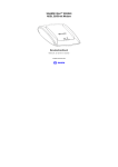
Package Contents
The following items should be found in your package:
¾
One TD-8841 External ADSL2+ Router
¾
One AC power Adapter for TD-8841 External ADSL2+ Router
¾
One Resource CD for TD-8841 External ADSL2+ Router, including:
z This Guide
z Quick installation Guide Program
z Other Helpful Information
z USB driver
¾
Quick installation Guide
¾
One RJ45 cable
¾
Two RJ11 cables
¾
One ADSL splitter
¾
One USB cable
) Note:
Make sure that the package contains the above items. If any of the listed items are damaged or
missing, please contact with your distributor.
1
TD-8841
External ADSL2+ Router User Guide
Chapter 1. Product Overview
With the excellent circuit design and high quality production, we guarantee the ADSL2+ Router’s
high performance, great stability and easy to use.
In addition to the basic DMT physical layer functions, the ADSL2+ PHY supports dual latency
ADSL2+ framing (fast and interleaved) and the I.432 ATM Physical Layer.
The TD-8841 is a complete plug-and-play solution. With standard Ethernet interface, it can be
directly connected to any 10M/100M Ethernet devices, support Auto-MDIX.
The TD-8841 not only uses html (web mode through Ethernet port) to configure the Router but
also uses external utility software. You can download it from our website (http://www.tp-link.com).
1.1 Product Main Specification
¾
High speed and asymmetrical data transmit mode, provides safe and exclusive bandwidth
¾
Supports All ADSL2+ industrial standards
¾
Compatible with all mainstream DSLAM (CO)
¾
Firmware upgradeable
¾
Provides integrated access of internet and route function which face to SOHO user
¾
Advanced DMT modulation and demodulation
¾
Real-time Configuration and device monitoring
¾
Quick response semi-conductive surge protection circuit, provides reliable ESD and
surge-protect function
1.2 Supporting Protocol
¾
G.992.1 (G.dmt) - Annex A/B/C
¾
G.992.2 (G.lite) - Annex A/B/C
¾
ANSI T1.413
¾
G.992.3 (ADSL2) Annex A/B/C/M and Annex L (RE-DSL) compliant
¾
G.992.5 (ADSL2+) Annex A/B/C and Annex L (RE-DSL) compliant
¾
ADSL dual latency (fast path and interleaved path)
¾
I.432 ATM physical layer compliant
¾
Supports RFC2364 (PPPoA)
¾
Supports RFC2516 (PPPoE)
2
TD-8841
¾
Supports RFC1483 (EoA)(Bridged *and Router)
¾
Supports RFC1577 (IPoA)
External ADSL2+ Router User Guide
) Note: “*” Needs the third-party software.
1.3 Transmit Data-rate
¾
Max download data-rate: 24Mbps
¾
Max upload data-rate: 3.5Mbps
¾
Max line length: 6Km
1.4 ATM Property
¾
AAL0, AAL5, OAM, RM, and raw cell types supported
¾
Direct hardware support for 4 Receive VCs, with additional RX VCs and TX VCs supported in
software
¾
Full 24-bit Virtual Path Identifier (VPI) and Virtual Circuit Identifier (VCI)
1.5 System Support
¾
Support PVC
¾
Support NAT、DHCP and so on
¾
Support IEEE 802.3、IEEE 802.3u
¾
Support 10Base-T/100BASE-TX full-duplex or half duplex Ethernet
¾
Support Auto-MDIX
¾
Support USB 1.1 device interface
1.6 Working Environment
¾
Operating temperature: 0 ℃~40 ℃
¾
Storage temperature: -40 ℃~70 ℃
¾
Humidity: 10%~90%
(non-condensing)
3
TD-8841
External ADSL2+ Router User Guide
Chapter 2. Hardware Installation Guide
The TD-8841 maintains six separate interfaces, including four Ethernet interfaces, one USB
interface and one ADSL interface. The Router should not be located where it will be exposed to
moisture or excessive heat. Place the Router in a location where it can be safely connected to the
various devices as well as to a power source.
2.1 System requirement
Confirm your computer has been installed with networking interface card (NIC) before connecting
ADSL2+ Router to your computer, with the operating system supporting the TCP/IP protocol.
2.2 LED explanation
The front panel of ADSL2+ Router includes one power indicator (RED) and eight function
indicators (GREEN), as explained in following chart:
Name
PWR
ADSL
ALARM
ACT
USB
LAN(1~4)
Status
Indication
On
Power OK
Off
Power fail
Slow flash
Self-detecting when power on
Quick flash
The LINE port is connecting to ISP’s network
On
The LINE port has connected to ISP’s network
Off
The LINE port has no connection
On
There is mistake when ADSL transmitting or receiving data
Off
ADSL normal
On
There is data transmitting or receiving on WAN port
Off
No data is being transmitted or received on WAN port
On
Connection to telecom network is OK
Off
Connection on USB port is abnormal
Flash
Data is being transmitted or received
On
LAN port is normal
Off
Connection on LAN port is abnormal
Flash
Data is being transmitted or received on LAN port
2.3 Rear-panel
¾
ON/OFF: Turn on/off the ADSL2+ Router’s power.
4
TD-8841
¾
External ADSL2+ Router User Guide
Power (9V AC/0.8A input): please do not use any unknown power adaptor; otherwise your
ADSL2+ Router may be damaged.
¾
RESET (reset default): First press the reset button of Router, then turn on the Router’s
power for at least three seconds. It will resume the default manufacturer’s setup.
¾
LAN: Connect with your computer’s NIC.
¾
USB: Connect with your computer’s USB interface
¾
LINE (WAN): Connect to the MODEM Port of Splitter or Connect to the telephone line.
2.4 Hardware installation procedures
The procedure to install the Router can be described in general terms in the following steps and
shown as Figure 2-1:
First Step: Connecting the MODEM port of Splitter with the LINE port of the TD-8841 ADSL2+
Router by telephone line. While you need to use a telephone, please attach telephone line into the
phone of Splitter.
Second Step: Connect category 5 cable with RJ45 jacks to ADSL2+ Router’s LAN port and your
computer’s NIC. Or connect USB cable to ADSL2+ Router’s USB port and your computer’s USB
interface.
Third Step: Plug one end of the AC Power Adapter into the Power jack on the Ethernet ADSL2+
Router and the other end to a standard electrical outlet.
Last Step: Check the line connection to see if everything is ready. Power up finally.
Figure 2-1
5
TD-8841
External ADSL2+ Router User Guide
Chapter 3. System Configuration
3.1 Computer Configuration
The default IP address of the ADSL2+ Router is 192.168.1.1, and the default Subnet Mask is
255.255.255.0. These values can be seen from the LAN, and can be changed as your desire. As
an example, we use the default values for description in this guide.
1.
Connect the cable according to Chapter 2, turn on the power.
2.
Connect the local PCs to the ADSL2+ Router’s LAN port. There are then two means to
configure the IP address for your PCs.
¾
Configure the IP address manually
¾
1)
Set up the TCP/IP Protocol for your PC(s).
2)
Configure the network parameters. The IP address is 192.168.1.xxx ("xxx" is from 2 to
254), Subnet Mask is 255.255.255.0, and Gateway is 192.168.1.1 (The ADSL2+
Router’s default IP address).
Obtain an IP address automatically
1)
Set up the TCP/IP Protocol in "Obtain an IP address automatically" mode on your
PC(s).
2)
The built-in DHCP server will assign IP addresses for the PC(s).
) Note:
If you need instructions as to how to do this, please refer toAppendix B: Configuring the PCs.
5
Remarks: you can check whether your configuration is successful through PING command. Enter
Ping 192.168.1.1
If the screen looks like the following, you have been successful.
If the screen looks like the following, the connection has failed. Please try again.
6
TD-8841
External ADSL2+ Router User Guide
3.2 Login
Startup Internet Explorer, and enter 192.168.1.1;then enter default user name (admin)、password
(admin), When ADSL2+ connection is OK, you will see the Figure 3-1.
Figure 3-1
You will then see the Figure 3-2. You will see some information such as link rate and so on.
7
TD-8841
External ADSL2+ Router User Guide
Figure 3-2
Default value of user name and password is “admin”; if you want to change them, please go to
“Management” Æ “Access control”Æ“Passwords” changing them. (Figure 3-3)
Figure 3-3
3.3 Web Setup
Choose “Advanced Setup”Æ”WAN”, you will enter the page of Wide Area Network (WAN) Setup,
you will see the Figure 3-4.
8
TD-8841
External ADSL2+ Router User Guide
Figure 3-4
There are 7 PVC links in the WAN setup page, choose the fit PVC according to your needs, and
then click the edit button, you will enter the page of ATM PVC Configuration (See Figure 3-5).
Figure 3-5
Enter VPI/VCI value and service category which is provided by your ISP, click next to enter the
next step. You will see the Figure 3-6.
9
TD-8841
External ADSL2+ Router User Guide
) Note:
The type of network protocol selected may be different in different areas, there are five types
(Figure 3-7), So you should ask your ISP to acquire the local type of network protocol and
Encapsulation mode.
Figure 3-6
After choosing the proper protocol, enter the correct parameters supported by your ISP. Enable
the configurations,then you will go to Internet.
¾
PPP over ATM (PPPoA)
If you select the protocol of PPP over ATM (PPPoA), you will see the Figure 3-7, enter the value
of user name and password which is provided by your ISP, after selecting the other function (often
using the default setup), click the next button.
10
TD-8841
External ADSL2+ Router User Guide
Figure 3-7
You will see the Figure 3-8. Then turn on the selected functions according to your demands.
Clicking the next button to enter the next step, you will see the Figure 3-9, finally click save to
complete the configuration.
Figure 3-8
11
TD-8841
External ADSL2+ Router User Guide
Figure 3-9
¾
PPP over Ethernet (PPPoE)
If you select the protocol of PPP over Ethernet (PPPoE), you will see the Figure 3-10, enter the
value of user name and password which is provided by your ISP, after selecting the other function
(often using the default setup), click the next button.
Figure 3-10
You will see the Figure 3-11. Then turn on the selected functions according to your needs.
Clicking the next button to enter the next step, you will see the Figure 3-12, finally click save to
complete the configuration.
12
TD-8841
External ADSL2+ Router User Guide
Figure 3-11
Figure 3-12
¾
MAC Encapsulation Routing (MER)
If you select the protocol of MAC Encapsulation Routing (MER), you will see the page (Figure
3-13) Enter the parameter and the way which is provided by your ISP, then click the next button.
13
TD-8841
External ADSL2+ Router User Guide
Figure 3-13
You will see the Figure 3-14. Then turn on the selected functions according to your needs.
Clicking the next button to enter the next step, you will see the Figure 3-15, finally click save to
complete the configuration.
Figure 3-14
14
TD-8841
External ADSL2+ Router User Guide
Figure 3-15
¾
IP over ATM (IPoA)
If you select the protocol of IP over ATM (IPoA), you will see the Figure 3-16, enter the parameter
and the way which is provided by your ISP, then click the next button.
Figure 3-16
You will see the page (Figure 3-17), then turn on the selected functions according to your needs.
Clicking the next button to enter the next step, you will see the Figure 3-18, finally click save to
complete the configuration.
15
TD-8841
External ADSL2+ Router User Guide
Figure 3-17
Figure 3-18
¾
Bridging
If you select the Bridging protocol, you just open the bridge service function options, you will see
the Figure 3-19, then click the next button, you will see the Figure 3-20, finally press save to
complete the configuration.
16
TD-8841
External ADSL2+ Router User Guide
Figure 3-19
Figure 3-20
) Note:
After you complete the settings, the new settings must be saved and the Router must be restarted
for the settings to go into effect. Please press the Save/Reboot button to restart, referring to the
Figure 3-21.
17
TD-8841
External ADSL2+ Router User Guide
Figure 3-21
3.4 Software Dial
If TD-8841 CPE work in bridged (RFC 1483 Bridged) mode when it connects Internet. You must to
install dial software on your PC. There are some software working on WINDOWS in market,
example for EnterNet3000、RASPPPoE、WinPeET.
How do I set up the connection in the windows XP?
¾
Users of Windows XP can click the “start->All Programs->Accessories->
Communications->New connection wizard”, then click Next to enter the setting page.
¾
Please you select the “connect to the internet” ,and then click the Next button to enter the
next page and select the “set up my connection manually”, click Next to enter the next
page.
¾
Please select the “connect using a broadband connection that requires user name and
password”, click Next to type the name of your ISP in the current page, and then click Next.
¾
Type an ISP account name and password, if you have forgotten an existing account name
or password, please connect with your ISP, click Next.
¾
To create the connection and close this wizard, click finish to add a shortcut to this
connection to your desktop.
¾
When you intend to assess the internet by ADSL, double-click this shortcut of dial connection
in your desktop, while type the account name and password, then click connect to connect
the Internet.
How do I set up the connection in the Windows Vista?
18
TD-8841
¾
External ADSL2+ Router User Guide
Users of Windows Vista can do as following: Right-press Network->Choose Properties,
then you can see Figure 3-22.
Figure 3-22
¾
Click “Set up a connection or network” in the right of this page. And choose “Set up a
dial-up connection” in the new page, click Next. After that, you will see Figure 3-23, click
“Set up a connection anyway” to enter next page.
Figure 3-23
19
TD-8841
¾
External ADSL2+ Router User Guide
Type the Dial-up phone number, the User name and password supplied by your ISP in the
new page, if you have forgotten an existing user name or password, please connect with your
ISP. Click Create to create the dial-up connection.
¾
Click Close to finish the setup.
¾
To connect to the Internet next time, click the Start button, click Connect to, and then click
the connection you just created.
3.5 USB Configuration
If you use the USB interface, First of all you must install the USB’s drive to the using computer.
You can obtain the drives from the provided CD or download from our website.
(http://www.tp-link.com)
USB Drive installation procedures
If the hardware is installed before the computer is Power On. Please turn on the computer and
enter into the windows operating system, Then the operating system will identify the device. If the
hardware is installed after the computer is Power On, the desktop will display the information of
found the new hardware.
Then you will see the Figure 3-24 require install software for USB Device, select ‘Install from a list
or specific location (Advanced)’and click the next button to enter the next step. You will see the
Figure 3-25.
Figure 3-24
20
TD-8841
External ADSL2+ Router User Guide
Figure 3-25
Select the ‘search removable media(floppy, CD-ROM…)’, and click the next button. You will see
the Figure 3-26. The driver will be search and installed.
) Note:
You must insert the CD first.
Figure 3-26
21
TD-8841
External ADSL2+ Router User Guide
Waiting and you will see the Figure 3-27. When the driver finished installation, click Finish to
close the installation.
Please refer to chapter 3.1 to finish the IP configuration of USB network connection. Then you
could use the USB device.
Figure 3-27
Users of Windows Vista will see the Figure 3-28. Click the “Locate and install driver software
(recommended)” to install driver software for your USB Network Interface.
22
TD-8841
External ADSL2+ Router User Guide
Figure 3-28
After that you will enter the next page shown as Figure 3-29. Click “Don’t search online”.
Figure 3-29
Then Figure 3-30 will be displayed. Click Next to search and install the driver from your CD.
) Note:
You must insert the CD first.
23
TD-8841
External ADSL2+ Router User Guide
Figure 3-30
When Windows find the driver automatically, it will pop up Figure 3-31. Select “Install this driver
anyway” to continue the installation.
Figure 3-31
Then please wait a second and you will see Figure 3-32 which indicates that the installation has
been finished. Finally, click Close to finish it completely.
24
TD-8841
External ADSL2+ Router User Guide
Figure 3-32
You can see following figure at the bottom of the screen.
Figure 3-33
) Note:
If you want cut off the USB device you must disconnect the network of USB first.
25
TD-8841
External ADSL2+ Router User Guide
Chapter 4. Advantage Management Setup
In order to satisfy our customer's needs we offer an excellent Web management interface. Feel
free to utilize the Advantage application and online software upgrades. The functions of the Web
management interface are as follows:
¾
Upgrade software
¾
Modify the default IP address of the port of LAN (192.168.1.1)
¾
Modify the login password
¾
Configure DHCP
¾
Check the information of IP and the operation status
¾
Configure the NAT function
¾
Configure the DNS parameters
¾
Configure RIP(Routing Information Protocol)
¾
Configure IP route
¾
Configure Security rule
¾
Configure DSL parameter
) Note:
If you want to acquire further details, please access our website (www.tp-link.com) and consult
the advantage user guide of TD-8841.
26
TD-8841
External ADSL2+ Router User Guide
Chapter 5. FQA
1.
What related parameters are required to acquire ISP when you want to access the
internet by ADSL2+ Router?
1)
Dial user: Connection protocol, User name, Password, Value of VPI/VCI, Encapsulation
mode of AAL5 and so on.
2)
Static IP user: Connection protocol, WAN IP Address, Subnet Mask, Gateway, Value of
VPI/VCI, Encapsulation mode of AAL5 and so on.
2.
3.
4.
About Connection protocol, VCI/VPI, Encapsulation mode of AAL5
1)
This product supports the PPP protocol over ATM (PPPoA) 、 PPP over Ethernet
(PPPoE)、MAC Encapsulation Routing (MER)、IP over ATM (IPoA) and Bridging. You
may be used with any one of the five protocols above. Because the ISP in different areas
supports different protocol, you must choose the protocol which is supported by your
ISP.
2)
The VPI is the English abbreviation of the Virtual Path Identifier, the VCI is the English
abbreviation of the Virtual Channel Identifier, the value of VCI/VPI must be compatible
with the value that provided by ISP.
3)
Encapsulation mode of AAL5 include: LLC/SNAP and VC_MAX (often using
LLC/SNAP).
Why the LAN’s and the NIC’s LED both bright, but the configuration interface is
inaccessible?
1)
Use the order of ping 192.168.1.1 to check the Accuracy of connection.
2)
Check the Accuracy of working NIC.
3)
Whatever the setup of the IP address on your computer (if you close the DHCP function,
you can't obtain the IP address automatically, must specify the IP address of your
computer manually).
4)
Run the winipcfg order in the windows 95/98(run the ipconfig order in the windows
2000/Vista) to check whether setup the IP address, subnet mask, default gateway by
DHCP.
5)
Resume the ADSL2+ Router default configuration if necessary.
Have completed all configurations, but can’t dial through computer
1)
Check the indicator of ADSL2+, it should be working normally.
2)
Check the accuracy of parameter of value of VPI/VCI, Encapsulation mode of AAL5 and
so on, whether you need to install the software of dial the number, such as Winpoet,
Enternet.
3)
This product has the PPP dial procedure inside, so you will not need to use the dial
software if your protocol is PPPoA or PPPoE, ADSL2+ Router will connect automatically.
4)
You can check whether your ADSL2+ Router succeeds in connection with PING
command.
27
TD-8841
External ADSL2+ Router User Guide
Appendix A: Default Configuration
USER NAME
admin
PASSWORD
admin
IP ADDRESS
192.168.1.1
VPI/VCI
0/32,1/33,0/35,0/100,0/200,8/35,8/81
28
TD-8841
External ADSL2+ Router User Guide
Appendix B: Configuring the PCs
In this section, we’ll introduce how to install and configure the TCP/IP correctly in Windows
2000/XP. First make sure your Ethernet Adapter is working, refer to the adapter’s manual if
needed.
1.
Install TCP/IP component
1)
Right-press Network Neighbor and Choose Properties.
2)
Right click the icon that showed below, select Properties on the prompt page.
Figure B-1
3)
In the prompt page that showed below, double click on the Internet Protocol (TCP/IP).
29
TD-8841
External ADSL2+ Router User Guide
Figure B-2
4)
The following TCP/IP Properties window will display and the IP Address tab is open on
this window by default.
Now you have two ways to configure the TCP/IP protocol below:
¾ Setting IP address automatically
Select Obtain an IP address automatically, Choose Obtain DNS server automatically, as
shown in the Figure below:
30
TD-8841
External ADSL2+ Router User Guide
Figure B-3
¾ Setting IP address manually
1
Select Use the following IP address radio button. And the following items available
2
If the router's LAN IP address is 192.168.1.1, type IP address is 192.168.1.x (x is from 2 to
254), and Subnet mask is 255.255.255.0.
3
Type the router’s LAN IP address (the default IP is 192.168.1.1) into the Default gateway
field.
4
Select Use the following DNS server addresses radio button. In the Preferred DNS
Server field you can type the DNS server IP address, which has been provided by your ISP.
31
TD-8841
External ADSL2+ Router User Guide
Figure B-4
Please note:
The configuration under Windows 98/Vista is a little different from that of Windows 2000/XP.
Users of Windows 98 can open TCP/IP Properties according to the following: Right-click (Mouse)
Network Neighbor -> Choose Properties -> Double-click TCP/IP PCI Fast Ethernet Adapter.
Users of Windows Vista can do following: Right-press Network->Choose Properties, then you
can see Figure B-5.
Figure B-5
Click “Manage network connections” in the right of this page. Then do as following: Right-press
Local Area Connection ->Choose Properties->Double click Internet Protocol Version 4
(TCP/IPv4).
32