1
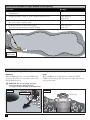
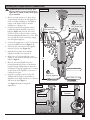
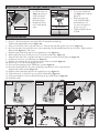
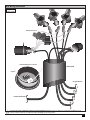
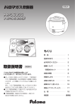
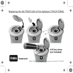
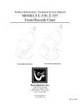
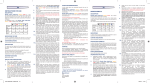
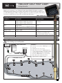
TWILIGHT GOLF POST LIGHT
Setup Guide
Thank you for purchasing a Toro Twilight Golf Post Light (TWGP). The lights are ideal for
illuminating practice putting greens, among other things. The Setup Guide is provided to assist
you with determining the number of lights needed, how to lay them out properly, make all wire
connections, install them into the ground, and make light adjustments.
TWGP-STAR36-12-L5
Lighting System Components
Equipment
Transformers
Hub
Wire
Lightpost stake
Twilight Golf Postlight
Part Number
TWGP-TRANS-360SS (Wall Mount)
TWGP-TRANS-360DB (Direct Burial)
TWGP-TRANS-1120SS (Wall Mount)
TWGP-HUB
(1 hub for 4 wire runs, 24 light fixtures max.)
TWGP-WIRE-12-2-500 (500’ per spool)
TWGP-STAKE
TWGP-STAR36-12-L5
LED lamp
Warranty Period
Limited lifetime warranty for repair or
replacement.
3 year
3 year
Limited lifetime for repair or replacement.
This warranty covers all parts and
components with the exception of the lamp.
5 year
Lighting System Sample Layout
CAUTION: Consult with a qualified electrician and local electrical codes
before installing any electrical product.
Figure 1
(not to scale)
Guidelines
TWGP-TRANS-360SS
Existing GFCI
Outlet
• Connect no more than 6 TWGP lights to each
wire run.
• Maximum 4 wire runs per hub.
• Bring all wire runs into a TWGP-HUB (close
to the postlight installation) and splice together
using the supplied water-proof connections.
From the TWGP-HUB, run a single “Home
Run” cable to the transformer location.
• Lights should be roughly 15’ apart.
TWGP-HUB
UNIQUE LIGHTING
“Home Run” Line
TWGP-WIRE-12-2-500
2
4
3
5
6
1
~15´
1
Determine the Number of Lights Needed and the Spacing
Directions
Example
1. Use a measuring wheel to determine the length of the perimeter of the area to
be illuminated.
2. The lights should be roughly 15’ apart. Divide the perimeter by 15.
Perimeter measures 352’.
3. Round that number UP to the nearest whole number.
That is the number of lights needed.
4. Divide the perimeter by the number of lights.
That is how far apart the lights should be installed.
Divide 352 by 15.
Equals 23.46.
Round 23.46 up to 24.
Divide 352 by 24.
Equals: 14.7´.
352’
Figure 2
(not to scale)
Notes Before Installing
Before installing the Twilight Golf Post lights, it is important to keep two things in mind during the installation planning.
Direction
Level
Before backfilling the hole, rotate the STAKE in the
ground so the notch points towards the center of the
desired illuminated area.
Before backfilling, use a bubble level to confirm the TWGPSTAKE is level in the ground. This ensures the light will come out
of the ground at 90˚.
! WARNING: Do not rotate light post once
inserted as this may damage the unit.
(See Figures 8 and 9 for lamp head adjustment.)
Figure 4
Figure 3
alignment notch
bubble level
2
Installing the Twilight Golf Post (TWGP-STAKE)
WARNING: Risk of electric shock. Turn
off power before servicing. Install all post
lights 10 feet (3.05m) or more from a pool,
spa, or fountain.
Figure 5
ToroCap: TWGP-ELECREC
1. Remove sod and excavate a 12” deep (below
aeration depth) trench for the UF supply line
cable or conduit and lightpost. The lightpost
requires a 10” diameter hole to facilitate
installation to a depth of 18”.
3
2
Insert wire nuts
into grease caps
and latch.
Insert wires into
wire nuts and twist.
2. Feed the incoming UF supply line cable or
conduit through the slanted bottom of the
lightpost (Figure 5-1). Provide 30” of wire
from the bottom to allow for future servicing.
If wiring multiple light fixtures in a series, make
sure you pull the second (continuing) supply
wire through the lightpost.
3. Connect the supply wires to the ToroCap’s wires
using the included wire nuts (Figure 5-2).
4. Encase all wire connections in the supplied
water-proof grease caps (Figure 5-3).
5. Push all wires back into the Landscape
LightPost and slide ToroCap back on.
6. Align holes on ToroCap with holes on the
Lightpost. Start all three included screws, then
tighten. (Figure 6).
30˝
7. Place the now wired LightPost into the
excavated trench and position to the desired
height. If wiring multiple fixtures, adjust the
incoming and outgoing supply wires or conduit
at the bottom of the LightPost so the wires or
conduit do not bind.
Lightpost: TWGP-STAKE
1
Feed wires
through lightpost.
8. Open the cover-flap on the ToroCap. The
Twilight Golf Post Light is keyed with an
alignment screw. Align with the slot on the base
and insert the light (Figure 7).
(See Figures 8 and 9 for lamp head
adjustments.)
Cable: TWGP-12-2-500
From transformer
Figure 6
To next light post
Figure 7
alignment screw
into notch
ToroCap
TWGP-STAKE
3
Adjusting the Twilight Golf Post Light (TWGP-STAR36-12-L5)
Figure 8
adjust head angle
Head Angle
1. Loosen the brass nut
(Figure 8) turning it
counter-clockwise.
2. Adjust the head to
the desired angle.
3. Retighten the brass
nut to hold desired
angle.
Figure 9
loosen Oribtal lock nut
to adjust direction
Direction
1. Loosen the Orbital lock
nut (Figure 9) around the
light post.
2. Rotate the head only
of the TWGP-STAR to
desired direction. Do
not rotate the lightpost as
damage may occur.
3. Tighten Orbital lock nut
by hand.
Wiring Inside the Hub
1. Feed all wires into the slanted end of the hub giving 12 of slack to allow for future servicing (Figure 16).
2. Strip 1/2” off each transformer wire and feed into an aluminum terminal lug.
Tighten with supplied Allen wrench (Figure 10).
3. Strip one end of each of the 5-amp fuse wires 1½˝. Twist the exposed ends together (up to four) (Figure 11).
4. Into the same side as the transformer wire of the terminal lug, feed the bundled wires into the other hole. Tighten with an
Allen wrench (Figure 11). Trim excess.
5. Push the wired terminal lug deep into the supplied grease cap (Figure 12).
6. Pull to tighten the zip-tie on the grease cap to secure the terminal lug. (Figure 13).
7. Twist the other end of the 5-amp fuse wire with one of the brown wires from the light runs (Figure 14).
8. Feed the two wires into a provided wire nut (Figure 14).
9. Push the wire nut deep into the provided grease cap and close the latch (Figure 14).
10. Repeat steps 7-9 for the remaining light run wires.
11. Now, twist the remaining brown TWGP lines together (Figure 15).
12. Insert the wired bundle into the other terminal lug, same direction as the transformer line.
Tighten with an Allen wrench (Figure 12).
13. Push the wired terminal lug deep into the supplied grease cap (Figure 12).
14. Tighten the zip-tie on the grease cap to secure the terminal lug (Figure 13).
15. Secure wire bundle to bottom of the hub lid using the pre-attached zip-tie (Figure 16).
16. Install lid on hub.
Figure 10
Figure 11
Figure 12
5-amp
fuse
wires
Figure 13
Figure 14
Figure 15
to
TWGP
lights
to TWGP light
4
Hub Wiring Illustration
Figure 16
(not to scale)
5-amp fuse wires
extra 5-amp fuses in the lid
TWGP-HUB
zip-tie
to light fixtures
1
2
from transformer
3
4
CAUTION: DO NOT OVERLOAD CABLE OR TRANSFORMER. Maintain polarity at all times. Consult with a qualified electrical
contractor and local eletrical code authorities before installing any electrical product.
5
Safety and Maintenance Notes
• Use with low-voltage, outdoor lighting system only.
• Lamp is hot when lit. Do not touch when lamp is on.
• Allow fixture to cool before touching or re-lamping
fixture.
• Do not operate fixture if cover shield is damaged or
missing.
• Do not submerse in water.
• Clean fixture with mild soap only. Do not use acid or
any other solvent base cleaner.
• Keep away from materials, structures, or landscapes that
may burn.
Specifications
•
•
•
•
Lamp: Flex Series 5 Watt LED
Electrical ratings: 12 VAC, Max 5W MR16 nominal
3’6” high from ground to highest point
Weight – 5.5 lbs.
•
•
•
•
250 lumens
2700 Kelvin color temperature
Solid brass construction
Light is removeable
Installation Notes
Toro Dedication to Quality
Toro is committed to developing and producing the highest quality, best performing, most dependable products on the market.
Because your satisfaction is our first priority, we have provided the Toro Helpline to assist you with any questions or problems
that may arise. If for some reason you are not satisfied with your purchase or have questions, please contact your local
authorized Toro dealer or e-mail [email protected].
6
© 2013 The Toro Company, Golf Division • www.toro.com • 1-877-345-8676 Form Number 373-0755 Rev. B