1
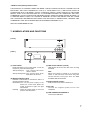
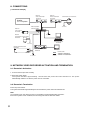
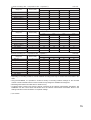
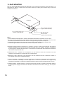
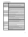
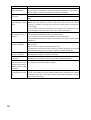
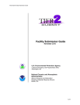
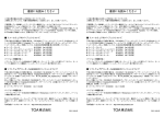
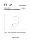
INSTRUCTION MANUAL
NETWORK VIDEO RECORDER
N-DR2000
TM
R
RO DD
ER
H
ER
W
PO
NETWORK VIDEO RECORDER N-DR2000
Thank you for purchasing TOA's Network Video Recorder. Please carefully follow the instructions in this
manual to ensure long, trouble-free use of your equipment.
TABLE OF CONTENTS
1. SAFETY PRECAUTIONS ............................................................................... 3
2. LIST OF INCLUDED COMPONENTS AND PARTS ............................... 5
3. GENERAL DESCRIPTION ............................................................................. 5
4. FEATURES .......................................................................................................... 5
5. SOFTWARE LICENSE ..................................................................................... 5
6. HANDLING PRECAUTIONS ........................................................................... 6
7. NOMENCLATURE AND FUNCTIONS ....................................................... 7
8. CONNECTIONS ................................................................................................. 8
9. NETWORK VIDEO RECORDER
ACTIVATION AND TERMINATION
9.1. Recorder's Activation ........................................................................................ 8
9.2. Recorder's Termination ..................................................................................... 8
10. FUNCTIONS
10.1. Device Functions ............................................................................................ 9
10.2. Recording ........................................................................................................ 9
10.2.1. Recording conditions ........................................................................ 10
10.2.2. Recording function priorities ............................................................. 10
10.2.3. Using multiple N-DR2000s ................................................................ 11
10.2.4. Recording loopback audio ................................................................ 11
10.2.5. 1000BASE-T ..................................................................................... 11
10.3. Search and Playback Using the N-SD2000 Software Decoder .................... 11
10.4. Making Settings Using a Web Browser ......................................................... 12
10.5. General Overview of N-DR2000 Settings ..................................................... 12
10.5.1. Recording settings ............................................................................ 12
10.5.2. Playback settings .............................................................................. 12
10.6. Email Malfunction Alert ................................................................................. 12
10.7. Time Adjustment ........................................................................................... 12
10.8. Retrieving the Recoded Video Images to a PC (Export function) ................. 12
11. OPERATION GUIDE LISTED BY OBJECTIVE ...................................... 13
12. RECORDING TIME LIST ............................................................................... 14
13. RACK MOUNTING .......................................................................................... 16
14. TROUBLESHOOTING ................................................................................... 17
15. SPECIFICATIONS ........................................................................................... 19
System Requirements (for N-SD2000 Software decoder) ..................................... 20
2
1. SAFETY PRECAUTIONS
• Before installation or use, be sure to carefully read all the instructions in this section for correct and safe
operation.
• Make sure to observe the instructions in this manual as the conventions of safety symbols and messages
regarded as very important precautions are included.
• We also recommend you keep this instruction manual handy for future reference.
Safety Symbol and Message Conventions
Safety symbols and messages described below are used in this manual to prevent bodily injury and property
damage which could result from mishandling. Before operating your product, read this manual first and
understand the safety symbols and messages so you are thoroughly aware of the potential safety hazards.
WARNING
Do not expose the unit to rain or an environment where it may be
splashed by water or other liquids, as doing so may result in fire or
electric shock.
WARNING
Indicates a potentially hazardous situation which, if mishandled, could
result in death or serious personal injury.
When Installing the Unit
• This is a class A product. In a domestic environment this product may cause radio interference in which case
the user may be required to take adequate measures.
• Use the unit only with the voltage specified on the unit. Using a voltage higher than that which is specified
may result in fire or electric shock.
• Do not cut, kink, otherwise damage nor modify the power supply cord. In addition, avoid using the power
cord in close proximity to heaters, and never place heavy objects -- including the unit itself -- on the power
cord, as doing so may result in fire or electric shock.
• Avoid installing or mounting the unit in unstable locations, such as on a rickety table or a slanted surface.
Doing so may result in the unit falling down and causing personal injury and/or property damage.
When the Unit is in Use
• If any of the following irregularities occurs, immediately switch off the power, disconnect the power supply
plug from the AC outlet and inform the shop from where the unit was purchased. Further using the unit may
result in fire or electric shock.
· If you detect smoke or a strange smell coming form the unit
· If water or any metallic object gets into the unit
· If the unit falls, or the unit case breaks
· If the power supply cord is damaged (exposure of the core, disconnection, etc.)
· If no image appears
• To prevent a fire or electric shock, never open the unit case nor modify the unit as there are high voltage
components inside the unit. Refer all servicing to your nearest TOA dealer.
• Do not place cups, bowls, or other containers of liquid or metallic objects on top of the unit. If they
accidentally spill into the unit, this may cause a fire or electric shock.
• Do not insert nor drop metallic objects or flammable materials in the ventilation slots of the unit's cover, as
this may result in fire or electric shock.
• Do not touch the power supply plug or control line during thunder and lightning, as this may result in electric
shock.
3
CAUTION
Indicates a potentially hazardous situation which, if mishandled, could
result in moderate or minor personal injury, and/or property damage.
When Installing the Unit
• Never plug in nor remove the power supply plug with wet hands, as doing so may cause electric shock.
• When unplugging the power supply cord, be sure to grasp the power supply plug; never pull on the cord
itself. Operating the unit with a damaged power supply cord may cause a fire or electric shock.When
removing the power cord, be sure to hold its plug to pull.
• When moving the unit, be sure to remove its power supply cord from the wall outlet. Moving the unit with the
power supply cord connected to the outlet may cause damage to the power supply cord, resulting in fire or
electric shock.
• Do not block the ventilation slots in the unit's cover. Doing so may cause heat to build up inside the unit and
result in fire.
• Avoid installing the unit in humid or dusty locations, in locations exposed to the direct sunlight, near the
heaters, or in locations generating sooty smoke or steam as doing otherwise may result in fire or electric
shock.
• Do not connect a network terminal exposed to excessive voltage to the 100BASE-TX terminal, Hard disk
expansion unit connection terminal or Remote control I/O terminal A, as doing so may result in fire or electric
shock.
When the Unit is in Use
• Do not place heavy objects on the unit as this may cause it to fall or break which may result in personal
injury and/or property damage. In addition, the object itself may fall off and cause injury and/or damage.
• Clean the unit periodically. Contact your TOA dealer regarding the cleaning. If dust is allowed to accumulate
in the unit over a long period of time, a fire may result.
• If dust accumulates on the power supply plug or in the wall AC outlet, a fire may result. Clean it periodically.
In addition, insert the plug in the wall outlet securely.
• Switch off the power, and disconnect the power supply plug from the AC outlet when cleaning or leaving the
unit unused for long periods of time. Doing otherwise may cause a fire or electric shock.
CU version complies with Part 15 of the FCC Rules.
Note
This equipment has been tested and found to comply with the limits for a Class A digital device,
pursuant to Part 15 of the FCC Rules. These limits are designed to provide reasonable protection
against harmful interference when the equipment is operated in a commercial environment. This
equipment generates, uses, and can radiate radio frequency energy and, if not installed and used in
accordance with the instruction manual, may cause harmful interference to radio communications.
Operation of this equipment in a residential area is likely to cause harmful interference in which case the
user will be required to correct the interference at his own expense.
Modifications
Any modifications made to this device that are not approved by TOA Corporation may void the authority
granted to the user by the FCC to operate this equipment.
4
2. LIST OF INCLUDED COMPONENTS AND PARTS
Check to be sure that the following components and parts are contained in the package:
Power supply cord (2 m) .................................................................................. 1
Network Video Recorder Instruction manual .................................................. 1
CD-ROM (Update disk) .................................................................................... 1
Note
The CD-ROM contains the updater for the N-SD2000 Software Decoder and the most recent firmware for
each device.
3. GENERAL DESCRIPTION
The N-DR2000 Network Video Recorder allows images and audio digital signals originating from network
cameras and network video transmitters connected to a LAN to be recorded to a hard disk drive.
Because the digital signals produced by such equipment are stored as is, they can be played back with high
clarity and quality.
It is possible to record images from up to 16 network cameras or network video transmitters at once, and to
record and play back up to eight images simultaneously.
With the use of a N-SD2000 software decoder, images stored on the network video recorder can also be
searched, retrieved, and played back.
The system also uses an NTP server function to synchronize the time throughout the system.
4. FEATURES
• Allows images (and audio) from network cameras/video transmitters, as well as event data, to be recorded,
distributed, and stored over a network.
• The recorder can have its settings adjusted over the network using a PC equipped with standard Web
browser software (such as Internet Explorer).
• An NTP server function can be used to synchronize the time throughout the system automatically.
• If the recorder malfunctions, an email notification can be sent to a pre-set email address to make the
administrator aware of the problem.
5. SOFTWARE LICENSE
This product uses software licensed under GNU General Public Licenses (GPL) and other forms of open
source software licensing.
• GNU General Public Licenses (GPLs)
Information on the Web regarding GNU General Public Licenses can be found at http://www.gnu.org.
• Extent of Warranty & Applicable Responsibilities
TOA does not guarantee the functioning of open source software covered under the conditions and
provisions of GPLs, etc., but does guarantee the function of items manufactured by the company itself.
• Information on Individual Open Source Software Products
Please contact TOA for more information on the open source software modules and their source codes used
in this product.
5
6. HANDLING PRECAUTIONS
• The supplied power supply cord is designed for exclusive use with the Recorder. Never use it with other
equipment.
• It is recommended that the Recorder be always used in locations where the ambient temperature ranges
from 0°C to +40°C and humidity levels of less than 80% to ensure that no condensation is formed.
• When moving or installing the Recorder, be absolutely sure to do so when the LED power indicator is
extinguished. If the LED power indicator is illuminated, follow the procedures for "Network Video Recorder
Activation and Termination," then wait at least 30 seconds before continuing with the movement or
installment.
• Avoid moving the Recorder suddenly from a cold location to a warm location, or installing it in close proximity
to an air-conditioner outlet, as internal condensation could result. When condensation occurs, do not switch
on the power until the Recorder has sufficiently dried.
• Avoid installing the Recorder in humid or dusty locations, or in locations exposed to direct sunlight, sooty
smoke or steam. Note that even in locations which are not particularly dusty, dust may accumulate at the
Recorder’s ventilation slots. Because this could cause an extreme rise in temperature inside the Recorder,
be sure to clean the ventilation slots periodically after switching off the power and disconnecting the power
supply cord from the AC outlet. It is highly recommended that the ventilation slots be cleaned once a year.
• When cleaning the Recorder, be sure to turn the power switch to OFF. Wipe with a soft dry cloth. If it gets
very dirty, use the soft cloth slightly moistened in neutral cleanser. Never use volatile spirits like thinner,
benzine, or alcohol. Such chemicals may damage its plastic surface.
• Do not block the ventilation slots or cooling fan, which could cause the temperature inside the Recorder to
rise, possibly resulting in unit failure. Install the Recorder at least 100 mm away from the nearest wall
surface.
• Since the Recorder is equipped with a cooling fan, a motor sound is generated.
• Do not install the Recorder in locations influenced by strong electrical or magnetic fields, as monitor screen
pictures may become distorted or the Recorder could fail.
• This Recorder is designed for use exclusively in commercial and industrial applications. General household
use may result in signal interference from radios, televisions, and similar electronic devices.
• Avoid jarring or striking the Recorder. The Recorder is a piece of precision equipment and accidentally
dropping it or subjecting it to strong impacts could cause its failure. When transporting the Recorder,
carefully pack it in the supplied carton to protect it from shock.
• Do not use this Recorder in areas where there are vibrations, as these may cause damage to the delicate
precision mechanisms within.
• Avoid installing the Recorder vertically or tilting it at extreme angles, since it is designed to be used in a
horizontal position only.
• About a hard disk
Hard disks other than those specified by TOA cannot be used. Since the hard disks are pieces of precision
equipment, take special care in handling not to accidentally drop, bump or jar them, lest they should fail.
If a hard disk on which condensation is formed is used, it could fail. Therefore, when brought into a warm
room from the cold outdoors, be sure to leave it unused for at least half a day before using it. If the hard disk
fails, recorded data cannot be restored.
• TOA takes no responsibility for any incidental damage, such as loss of sales opportunities, that may result.
• Using this Recorder with an unstable electrical power supply may cause malfunctions or mistaken
operations. If the power supply is unstable, it is recommended to connect the Recorder to that power supply
using an uninterruptible power supply (UPS).
• Recording may be interrupted if a network failure such as packet loss occurs.
6
• MPEG-4 visual patent portfolio license
THIS PRODUCT IS LICENSED UNDER THE MPEG-4 VISUAL PATENT PORTFOLIO LICENSE FOR THE
PERSONAL AND NON-COMMERCIAL USE OF A CONSUMER FOR (1) ENCODING VIDEO IN
COMPLIANCE WITH THE MPEG-4 VISUAL STANDARD (“MPEG-4 VIDEO”)AND/OR (2) DECODING
MPEG-4 VIDEO THAT WAS ENCODED BY A CONSUMER ENGAGED IN A PERSONAL AND NONCOMMERCIAL ACTIVITY AND/OR WAS OBTAINED FROM A VIDEO PROVIDER LICENSE BY MPEG LA
TO PROVIDE MPEG-4 VIDEO. NO LICENSE IS GRANTED OR SHALL BE IMPLIED FOR ANY OTHER
USE. ADDITIONAL INFORMATION INCLUDING THAT RELATING TO PROMOTIONAL, INTERNAL AND
COMMERCIAL USES AND LICENSING MAY BE OBTAINED FROM MPEG LA,LLC.
SEE HTTP://WWW.MPEGLA.COM.
7. NOMENCLATURE AND FUNCTIONS
[ Front ]
TM
E
G
SA D
ES
M
HD
ER
W
PO
RECORDER N-DR2000
VIDEO REC
R20
NETWORK
WOR VID
2 3 4 1
[ Rear ]
5
6
(1) Power switch
Press this switch to turn on the power. To turn off
the power, press this switch again.
After powering up : The system starts after
about 1 minute.
After powering down: The system shuts down
after about 30 seconds
(2) Message Indicator (Red)
Flashes or illuminates to indicate the action of
internal protection circuits.
Illuminated: Turn off the power supply to the
device for a short time. When the
power is turned on again, the light
should flash.
Flashing : Press the power switch on the front
panel to start the device.
(3) HDD access Indicator (Yellow)
LED flashes when the hard disk drive is being
accessed.
Note
When the system is started up, it performs a
check on the hard disk drive which may take
several minutes. During this time, the HDD
ACCESS LED will illuminate.
(4) Power Indicator (Green)
Flashes when the power is switched on.
(5) AC inlet
Connect the supplied power cord to this
receptacle.
(6) LAN 100BASE-TX/1000BASE-T
Connect the LAN cable.
7
8. CONNECTIONS
[ Connection example ]
Network
Video Transmitter
N-VT2010
Network
Video Transmitter
N-VT2010
Analog
CCTV system
Combination Dome Camera
RS-485
To 24V AC
PoE compatible
switching HUB
Network
Color Camera
N-CC2360
8
7
6
5
4
3
2
1
DC-IN
To AC Main
Network
Combination Dome Camera
N-CC2564
Software Decoder
N-SD2000
To 24V AC
Network Video Recorder
N-DR2000
Network Video Receiver
N-VR2010
TM
R
D
RO
ER
HD
ER
W
PO
Monitor
NETWORK V IDEO RECORDER N- DR2000
: Coaxial cable
: 10BASE-T/100BASE-TX
: 100BASE-TX/1000BASE-T
To AC Main
9. NETWORK VIDEO RECORDER ACTIVATION AND TERMINATION
9.1. Recorder's Activation
1. Connect each component correctly.
2. Press the power switch.
The system activates approximately 1 minute after the power has been switched on. The power
automatically switches on with the power cord is connected.
9.2. Recorder's Termination
Press the power switch.
The system terminates approximately 30 second after the power has been switched off.
Note
It is possible to turn the device off even in the middle of a Normal Recording operation.
Even if the system is then restarted, the recording will continue after the restart.
8
10. FUNCTIONS
10.1. Device Functions
The device is equipped with the following functions.
•
•
•
•
•
Recording (Normal Recording, Pre-Alarm Recording, Alarm Recording, Scheduled Recording)
Search and playback using the N-SD2000 Software Decoder
Setting adjustment using a Web browser
Email notification in the event of malfunction
Time adjustment and synchronization
10.2. Recording
The device offers the following four types of recording functions.
[ Normal Recording ]
Records normal images and audio from designated equipment including the network camera/video
transmitter. Refer to the Setting Manual (Chapter3) for more information.
[ Pre-Alarm Recording ]
Pre-Alarm Recording records images and audio transmitted up to five minutes before an alarm was triggered.
Note
The Pre-Alarm recording setting takes precedence over both Normal and Scheduled recording. Video images
from the network camera/video transmitter set for pre-alarm recording cannot be recorded will not record in
the Normal or Scheduled recording modes even if they are set to do so.
[ Alarm Recording ]
The network camera/video transmitter are all equipped with contact input and motion detection-based alarm
functions. When set to Alarm recording, the images from these can be recorded on the N-DR2000 whenever
an alarm occurs. The specific recording conditions for Alarm recording are set on the network camera/video
transmitter respectively.
• Alarm priority
If multiple alarm activations are duplicated in the system comprising of a single network camera and a video
transmitter, these alarm priority levels determine the recording conditions such as which N-DR2000 to record
the video images, and video and audio parameters. Two levels of alarm priority are available, Levels 1 (high)
and 2 (low). When Level 1 alarms are duplicated, the recording is made on a first-in-first-out basis, while if
Level 2 alarms are duplicated, it is made on last-in-first-out basis.
Set the alarm priority using the network camera or the video transmitter.
• Connection type and recording time
Two connection types are available for the Contact-in alarm recording, single-edge and double-edge. For the
single-edge Contact-in alarm recording or motion-detected alarm recording, alarm recording time can be set in
the range of 1 to 120 minutes with the N-DR2000's edge-alarm recording setting.
For the double-edge Contact-in alarm recording, recording continues until the Contact-in becomes off state.
Connection type can be set using the network camera or the video transmitter.
Refer to the Setting Manual (Chapter3) for more information.
Note
Since the device performs alarm recording via the network, it may take several seconds to start recording after
an alarm has been detected.
[ Scheduled Recording ]
The device can be set to record images and audio from the network camera/video transmitter at a preestablished time. Images and audio from the Multiple network cameras/video transmitters can be set in a
single program. Refer to the Setting Manual (Chapter6) for more information.
9
10.2.1. Recording conditions
This device is equipped with a variety of recording functions. These can be set individually to use specific
recording conditions. For example, Normal recording can be set to record at 1 frame per second (fps), while
Scheduled recording records at 5 frames per second. For each recording function, the following settings are
available.
Frame Rate
Recording can proceed at a maximum speed of five frames per second (1, 2, 3 or 5 fps). The higher the frame
rate setting, the more hard disk drive space will be required to store the resulting recordings, thus shortening
total available recording time.
Picture Quality
Five levels (1–5) of picture quality are available, with "1" being the highest quality. Higher quality images
require more hard disk drive space to store, and thus reduce total available recording time.
Size
Three levels of image size are available. Select from High:D1, Medium:Half D1 or Low:QVGA (CU)/ CIF (PL).
Larger images require more hard disk drive space to store, and thus reduce total available recording time.
Audio
Audio recording can be turned On or Off. The audio compression format is set on the network camera/video
transmitter. With the N-SD2000, audio recording is available for all recording modes. Also, by making settings
to the network camera/video transmitter, it is possible to perform loopback recording.
High
Alarm Recording
10.2.2. Recording function priorities
This device uses different types of recording programs to control
recording priorities.
Pre-Alarm Recording
Recording
priority level
Scheduled Recording
Normal Recording
Low
(Example)
If an alarm occurs for a camera in Normal Recording mode...
Since Alarm recording has a higher priority than Normal recording, the device switches to Alarm recording,
then reverts to Normal recording once the Alarm recording has finished.
Camera's recording mode
Normal recording
Alarm recording
Alarm occurs.
Normal recording
Alarm ends.
The network camera/video transmitter all have their own independent priority control. For example, if Camera
1 is in Normal recording and an alarm causes Camera 2 to shift to Alarm recording, the Normal recording by
Camera 1 continues unaffected.
Normal recording
Camera 1
Camera 2
Camera 3
Normal recording
Normal recording
Normal recording
Alarm recording
Scheduled recording
Camera 4
Normal recording
Camera 5
Standby Pre-recording
Scheduled recording
Normal recording
Alarm recording
Pre-Recording
Scheduled recording Normal recording
Alarm recording
Standby Pre-recording
Note
A blank duration (unrecorded interval) occurs when a recording mode is switched to another. The lower frame
rate may cause the blank duration to be several seconds.
10
10.2.3. Using multiple N-DR2000s
It is not possible to record from the network camera/video transmitter to two or more N-DR2000s
simultaneously. However, if one N-DR2000 is set to execute Normal recording and another N-DR2000 is set
for Alarm recording, then according to priority control the Alarm recording will take precedence. In the even of
an alarm, the second N-DR2000 will begin Alarm recording and the first N-DR2000 will stop Normal recording
until Alarm recording is finished.
10.2.4. Recording loopback audio
The N-DR2000 may be used to record audio from a device connected to the network camera/video
transmitter. This function allows conversations with the N-VR2010 and N-SD2000 to be recorded.
10.2.5. 1000BASE-T
Depending on recording conditions, transmission using the lower 100BASE-TX standard may cause frame
loss or audio skipping. If this happens, it may be necessary to connect the N-DR2000 to the port of a hub
supporting 1000BASE-T switching.
10.3. Search and Playback Using the N-SD2000 Software Decoder
Video and audio recorded on the N-DR2000 can be searched and played back using the N-SD2000 Software
Decoder. The N-SD2000 Software Decoder can search for events, and also filter these according to more
specific criteria to narrow down the choices. Up to 8 pieces of recorded video and audio can be played back
simultaneously on the N-SD2000 Software Decoder. It is also possible to perform recording and playback at
the same time. Both the playback speed and playback direction can be designated for the recorded video.
Refer to the instruction manual of the N-SD2000 Software Decoder for more information.
(Example)
PC 1 displays 4-split screen,
while PCs 2 through 5 all display single-split screen each,
reaching the maximum limit of 8 simultaneous connections.
PC1
PC2
Camera 1
PC3
HUB
PC4
N-DR2000
PC5
View 1 : 1 – 4
View 2 : 1
View 3 : 1
View 4 : 1
View 5 : 1
Camera 16
Allows playback of up to 8 views simultaneously.
Notes
• Recordings can be played back on different PCs.
• Up to four views can be displayed on a single PC.
11
10.4. Making Settings Using a Web Browser
The N-DR2000 is equipped with its own Web server function. You can access this server via Web browser
software in order to change the N-DR2000's status displays and various settings, and also to conduct
maintenance.
10.5. General Overview of N-DR2000 Settings
A Web browser can be used to perform the N-DR2000's various settings.
10.5.1. Recording settings
1. Use the Web browser to set the N-DR2000's network parameters, time, and hard disk drive overwrite mode.
IP addresses are also settable using the N-SD2000 software decoder. Refer to the N-SD2000 software
decoder instruction manual for more information.
• For IP address, subnet mask, and default gateway settings, Refer to Setting Manual (Chapter6).
• For hard disk drive overwrite mode settings, Refer to Setting Manual (Chapter6).
2. Register the network camera/video transmitter units from which the N-DR2000 is to record.
For IP address and name settings, Refer to Setting Manual (Chapter6).
3. Set the various recording functions to be used for each network camera/video transmitter.
For Normal recording, Pre-Alarm recording, and Scheduled recording settings.
To use Alarm recording, the network camera/video transmitter must be set to do so. These settings can be
made for each unit in the same way as the N-DR2000, via a Web browser. Refer to the Setting Manual
(Chapter3) for more information.
10.5.2. Playback settings
Use the N-SD2000 software decoder to register the N-DR2000.
In the N-DR2000 Connection Parameter Settings, match the SIP password with the administrator password
set in the N-DR2000 System Settings. Refer to the N-SD2000 software decoder instruction manual for more
information.
10.6. Email Malfunction Alert
The email malfunction alert function automatically sends an email notification about abnormal N-DR2000
operating conditions, including rising internal temperature, abnormal fan rotation, and hard disk drive errors.
10.7. Time Adjustment
The N-DR2000's internal NTP server can be made to access an external NTP server in order to adjust its own
internal clock. Also, by setting the NTP servers of the network camera, video transmitter, and video receiver,
these devices can also be made to adjust their internal clocks. Refer to the instruction manuals for each
device for details.
10.8. Retrieving the Recoded Video Images to a PC (Export function)
Video images recorded on the N-SD2000 can be retrieved to a PC via a network. (Export function) The
N-SD2000 Software Decoder can convert up to 10-minute video images to ASF format data and save them to
a PC.
12
Note: Audio signals cannot be retrieved.
11. OPERATION GUIDE LISTED BY OBJECTIVE
Item
Description
Reference
Always record video and audio. Set the Normal recording mode.
Setting Manual
(Chapter6)
Make regularly scheduled
recordings at pre-set times.
By setting Scheduled recording, the recording occurs only
at the specified times.
Setting Manual
(Chapter6)
Want to always record images
from a network camera, but at
certain times only change the
recording conditions.
By setting both Normal recording and Timer recording, it is
possible to have Scheduled recording take place only at
specified times and using particular recording conditions
set for Timer recording.
Setting Manual
(Chapter6)
Use Alarm recording.
Alarm recording can be set for network cameras and video
transmitters.
Setting Manual
(Chapter3)
Record images only when an
alarm has occurred.
If neither Normal recording nor Scheduled recording are set,
then a setting on the network camera itself can be used to
execute only Alarm recording.
Setting Manual
(Chapter3)
Want to always record images
from a network camera, but also
change the recording conditions
used for Alarm recording.
When an alarm occurs for a network camera that is operating in Normal recording mode, the mode switches to Alarm
recording automatically. Refer to the instruction manuals for
such devices for details.
Use Pre-Alarm recording.
Pre-Alarm recording records the images and audio that occurred in the five minutes prior to the commencement of an
Alarm recording.
Note: Pre-Alarm recording takes priority over Timer recording. Video images from the network camera/video
transmitter set for Pre-Alarm recording can not be
recorded even if set for other modes such as Timer
recording.
Setting Manual
(Chapter3, 6)
Setting Manual
(Chapter6)
Want to search among recorded It is possible to search the recordings made by the Nimage segments.
DR2000 using the N-SD2000 (software decoder). Criteria
for narrowing the found data can use time specification and
a variety of other filtering methods. Refer to the N-SD2000
instruction manual for more details on search execution and
filtering.
N-SD2000
Instruction
Manual
Use the N-SD2000 to drag and drop the found recording
content into the View window to initiate playback. Playback
options include normal playback, reverse playback, fastforward or fast-reverse playback, and playback pause.
Refer to the N-SD2000 instruction manual for more details
on search execution and filtering.
N-SD2000
Instruction
Manual
Want to play back recorded
images and audio.
Retrieving the recoded video
images to a PC.
Recording content being played back by the N-SD2000 can
be converted into ".asf" files containing up to ten minutes of
image. Such files created using the N-DR2000 can be played using Windows Media Player or equivalent software.
Refer to the N-SD2000 instruction manual for more details
on creating files for storage.
N-SD2000
Instruction
Manual
Note: Audio signals cannot be retrieved.
13
12. RECORDING TIME LIST
Chart shows approximate recording times for each camera assuming 16 cameras or video transmitters are in
use.
Audio recording: None (*1)
Image size
Unit: Hour
Frame rate per camera
Picture quality
1 fps
2 fps
3 fps
5 fps
64
43
25
High: D1
1
129
High: D1
3
186
93
62
37
High: D1
5
337
168
112
67
Medium: Half-D1
1
192
96
64
38
Medium: Half-D1
3
276
138
92
55
Medium: Half-D1
5
493
246
164
98
Low: QVGA
1
364
182
121
72
Low: QVGA
3
521
260
173
104
Low: QVGA
5
958
479
319
191
Audio recording: 32 K Compression: OFF (*1)
Image size
Unit: Hour
Frame rate per camera
Picture quality
1 fps
2 fps
3 fps
5 fps
68
44
33
21
High: D1
1
High: D1
3
81
56
43
29
High: D1
5
101
78
63
46
Medium: Half-D1
1
83
58
44
30
Medium: Half-D1
3
95
70
56
40
Medium: Half-D1
5
112
91
77
58
Low: QVGA
1
104
81
66
48
Low: QVGA
3
114
93
79
60
Low: QVGA
5
126
111
100
82
Audio recording: 32 K Compression: ON *
( 1)
Image size
Unit: Hour
Frame rate per camera
Picture quality
1 fps
2 fps
3 fps
5 fps
High: D1
1
104
57
39
24
High: D1
3
138
79
55
34
High: D1
5
208
128
93
60
Medium: Half-D1
1
142
81
57
36
Medium: Half-D1
3
183
110
78
50
Medium: Half-D1
5
258
169
126
83
Low: QVGA
1
218
136
99
64
Low: QVGA
3
266
176
131
87
Low: QVGA
5
346
254
201
141
Audio recording: 8 K Compression: ON *
( 1)
Image size
14
Picture quality
Unit: Hour
Frame rate per camera
1 fps
2 fps
3 fps
5 fps
High: D1
1
119
62
41
25
High: D1
3
166
87
59
36
High: D1
5
275
151
104
64
Medium: Half-D1
1
170
90
61
37
Medium: Half-D1
3
233
110
86
53
Medium: Half-D1
5
371
212
148
92
Low: QVGA
1
293
162
112
69
Low: QVGA
3
387
222
155
97
Low: QVGA
5
585
363
263
170
Audio recording: 32 K Compression: OFF Loopback (*1)
Image size
Picture quality
Unit: Hour
Frame rate per camera
1 fps
2 fps
3 fps
5 fps
High: D1
1
46
34
27
19
High: D1
3
52
40
33
24
High: D1
5
60
50
44
35
Medium: Half-D1
1
52
41
34
25
Medium: Half-D1
3
57
47
40
31
Medium: Half-D1
5
63
56
50
41
Low: QVGA
1
60
52
45
36
Low: QVGA
3
64
57
51
42
Low: QVGA
5
67
63
59
52
Audio recording: 32 K Compression: ON Loopback (*1)
Image size
Picture quality
Unit: Hour
Frame rate per camera
1 fps
2 fps
3 fps
5 fps
High: D1
1
87
52
37
23
High: D1
3
110
69
50
32
High: D1
5
150
104
79
54
Medium: Half-D1
1
112
71
51
33
Medium: Half-D1
3
136
91
68
45
Medium: Half-D1
5
175
129
102
72
Low: QVGA
1
155
109
83
57
Low: QVGA
3
178
133
105
75
Low: QVGA
5
211
173
146
112
Audio recording: 8 K Compression: ON
Image size
Picture quality
Loopback (*1)
Unit: Hour
Frame rate per camera
1 fps
2 fps
3 fps
5 fps
High: D1
1
110
59
40
25
High: D1
3
149
83
57
35
High: D1
5
233
137
97
61
Medium: Half-D1
1
153
85
59
36
Medium: Half-D1
3
202
116
82
51
Medium: Half-D1
5
298
185
135
87
Low: QVGA
1
245
146
104
66
Low: QVGA
3
307
193
141
91
Low: QVGA
5
421
292
224
152
• Depending on recording conditions, actual available recording times may be shorter than those listed in this
chart.
• Using the N-DR2000, it is possible to conduct a variety of recording condition settings for the recorded
content of each individual camera. These conditions may change the available recording time.
• Recording times listed in the table are for reference only.
• Loopback refers to audio input from the device connected to the network camera/video transmitter. The
N-DR2000 can also record audio transmitted from the network camera/video transmitter. Refer to the
settings manual for more information on loopback settings.
(*1) CU
version
15
13. RACK MOUNTING
Use the optional MB-23B Rack Mounting Bracket when mounting the Network Video Recorder in an
equipment rack. Remove 4 rubber feet on the bottom surface by loosening their respective fixing screws with
a standard screwdriver.
N-DR2000
NE
TW
M5 x 12 binding head screw
(supplied with the MB-23B)
ERRO
OR
K
R
HDD
VIDE
O
POWER
RE
CO
RD
ER
N-DR
2000
M4 x 12 binding head screw
(supplied with the MB-23B)
MB-23B (optional)
M5 fiber washer
(supplied with the MB-23B)
Notes
• Use the Network Video Recorder in locations with ambient temperature of between 0°C and +40°C.
• Be sure to mount the Network Video Recorder below the heat generating components, and mount the
perforated panel between the Recorder and such a heat generating component as required.
• The Network Video Recorder has a built-in cooling fan. Never block the Recorder’s ventilation slot.
• Avoid installing the Network Video Recorder in locations exposed to vibration.
a) Elevated Operating Ambient Temperature - If installed in a closed or multi-unit rack assembly, the operating
ambient temperature of the rack environment may be greater than room ambient. Therefore, consideration
should be given to installing the equipment in an environment compatible with the manufacturer's maximum
rated ambient temperature (Tmra).
b) Reduced Air Flow - Installation of the equipment in a rack should be such that the amount of air flow
required for safe operation of the equipment is not compromised.
c) Mechanical Loading - Mounting of the equipment in the rack should be such that a hazardous condition is
not achieved due to uneven mechanical loading.
d) Circuit Overloading - Consideration should be given to the connection of the equipment to the supply circuit
and the effect that overloading of circuits might have on overcurrent protection and supply wiring.
Appropriate consideration of equipment nameplate ratings should be used when addressing this concern.
e) Reliable Earthing - Reliable earthing of rack-mounted equipment should be maintained. Particular attention
should be given to supply connections other than direct connections to the branch circuit (e.g., use of power
strips).
16
14. TROUBLESHOOTING
Possible Solution
Problem
Power won't turn on.
Check to make sure the power cord is plugged in to both the unit and the wall
socket.
Unit won't turn off even The power indicator LED takes about 30 seconds to extinguish after the power
after pressing the switch is pressed. Wait 30 seconds or so to see if the light goes off.
power switch.
Can’t access the unit Check to ensure that the unit is correctly connected to the network.
Check the unit's network settings.
using a Web browser.
Check whether the correct address was entered into the browser’s address
window.
Check the user name and password used to access the unit using the browser.
The factory defaults for these are "admin" for the user name and "guest" for the
password.
Scanning does not find If the IP address of the Network Video Recorder is the same as that of the PC, then
the Network Digital Re- the recorder cannot reply to the scan and therefore is not recognized. Set the
corder on the network. recorder to have a different IP address than the PC.
Cannot make settings.
Cannot search.
Cannot record.
Some setting items are unavailable while the unit is in Recording or Standby
Record mode. Stop the recording and enter the Recording not available mode in
order to be able to make such settings.
Check the “N-SD2000 connection parameters: SIP password.”
It is necessary for this password to match the N-DR2000 administrator password.
Check to ensure that the network video transmitter and network camera are
connected to the network correctly.
Check to see if the N-DR2000 in Recording not available mode.
If it is, use the Web browser to access the window with the Record button and
press this button to change the mode to allow recording.
Check to see if the camera registration has been set properly.
Check to see that the port number and SIP password in the camera preset settings
match those set for the network video transmitter/network camera.
Check to see if Alarm recording target and recording conditions, etc. have been set
properly on the network video transmitter/network camera.
Cannot use Normal Check the Normal recording/Pre-Alarm recording settings.
recording. Cannot use
Pre-Alarm recording.
Cannot use Scheduled Check the Scheduled recording settings.
Check to make sure the time is set correctly.
recording.
Cannot use Alarm rec- Check to make sure that the external signal is being input correctly to the contact
inputs of the network video transmitter/network camera.
ording.
Check to make sure that the recording settings of the device connected to the
network video transmitter and network cameras are performed correctly.
Check to make sure that the external audio source is correctly connected to the
Cannot record audio.
network video transmitter.
Check to make sure that "Audio" for each recording setting is set to "On."
17
Problem
Possible Solution
The HDD ACCESS
Following a restart, an automatic disk check program will run automatically. Wait
LED is illuminated.
until this check is completed. If the lamp remains illuminated for more than 15
minutes, leave the power on and contact your nearest TOA dealer.
The MESSAGE LED is Disconnect and reconnect the main AC power supply.
illuminated.
If the unit seems to not restart after reconnecting the power, press the power
switch.
A hard disk access
Displayed whenever a problem of reading or writing to the hard disk drive in the Nerror message is disp- DR2000 has been detected. Check to make sure that the unit is not being
layed.
subjected to vibrations or shocks, then press the Confirm button to dismiss the
error message.
If such hard disk access error messages occur frequently, the hard disk drive itself
may be damaged. If this is the case, consult your nearest TOA dealer.
An internal temperature This warning is displayed if the internal temperature of the N-DR2000 rises
abnormality warning is inordinately beyond acceptable limits. Check the following:
displayed.
• Is the case fan on the back of the N-DR2000 functioning properly?
• Is the N-DR2000 positioned so that its rear surface is too close to a wall or other
obstruction?
A case fan malfunction This warning is displayed if the rotation speed of the N-DR2000’s case fan drops
warning is displayed.
inordinately low.
Check to make sure there is nothing blocking the fan.
If no obstruction is found and the fan continues to perform improperly, the fan itself
may be malfunctioning. If this is the case, consult your nearest TOA dealer.
A CPU fan malfunction This warning is displayed if the rotation speed of the N-DR2000’s CPU fan drops
warning is displayed.
inordinately low. Consult your nearest TOA dealer.
A low battery warning
is displayed.
Displaying the results
of a recording search
conducted using the N-
This warning is displayed if the voltage of the N-DR2000’s internal battery drops
inordinately low. Consult your nearest TOA dealer to replace the battery.
It is normal for there to be a delay of up to 30 seconds when displaying the results
of a recording search executed after a restart.
SD2000 seems to take
a long time.
Recordings sometimes Factors including network conditions and malfunction detection functions can
are interrupted or break interrupt communications from the network camera/video transmitter. If the signal
up.
is interrupted in this way, recording is forced to stop and then start again, resulting
in disconnected recordings.
18
15. SPECIFICATIONS
[N-DR2000 CU]
Power Source
Power Consumption
Recording Storage
Network
Network I/F
Network Protocol
Frame Rate
Recording Method
Number of Simultaneous
Recording
Recording Mode
Image Quality
Resolution
110 – 120 V AC, 50/60 Hz
57 W (0.8 A)
HDD S-ATA 640 GB (320 GB x 2)
Other Function
Altitude
Operating Temperature
Operating Humidity
Finish
Dimensions
Alert notification via e-mail, Time synchronization, Operation log
Under 3,000 m (10,000 ft) (relative to sea level)
0ºC to + 40ºC (32ºF to 104ºF)
20% to 80% RH (no condensation)
Case: Pre-coated steel plate, black
420 (W) x 88.7 (H) x 320.5 (D) mm (16.54" x 3.49" x 12.62") (Excluding the
projection and the rubber feet.)
6.1 kg (13.45 lb)
Weight
100BASE-TX/1000BASE-T, Auto-Nego: RJ45 connector
TCP, UDP, SIP, RTP, HTTP, SMTP, ARP, DNS, NTP
Settable 1, 2, 3, 5 fps (Per Network Camera and Network Video Transmitter)
Video: JPEG Audio: sub-band ADPCM, PCM (non-compression)
Up to 16 stations (Network Camera or Network Video Transmitter)
Normal, Scheduled, Alarm, Pre-alarm
5 level adjustment
D1 (720 x 480), Half D1 (720 x 240), QVGA (320 x 240):
NTSC (depends on camera type)
Note: The design and specifications are subject to change without notice for improvement.
19
[N-DR2000 PL]
Power Source
Power Consumption
Recording Storage
Network
Network I/F
Network Protocol
Frame Rate
Recording Method
Number of Simultaneous
Recording
Recording Mode
Image Quality
Resolution
220 – 240 V AC, 50/60 Hz
57 W (0.8 A)
HDD S-ATA 640 GB (320 GB x 2)
Other Function
Altitude
Operating Temperature
Operating Humidity
Finish
Dimensions
Weight
Alert notification via e-mail, Time synchronization, Operation log
Under 3,000 m (10,000 ft) (relative to sea level)
0ºC to + 40ºC (32ºF to 104ºF)
20% to 80% RH (no condensation)
Case: Pre-coated steel plate, black
420 (W) x 88.7 (H) x 320.5 (D) mm (16.54" x 3.49" x 12.62")
6.1 kg (13.45 lb)
100BASE-TX/1000BASE-T, Auto-Nego: RJ45 connector
TCP, UDP, SIP, RTP, HTTP, SMTP, ARP, DNS, NTP
Settable 1, 2, 3, 5 fps (Per Network Camera and Network Video Transmitter)
Video: JPEG Audio: sub-band ADPCM, PCM (non-compression)
Up to 16 stations (Network Camera or Network Video Transmitter)
Normal, Scheduled, Alarm, Pre-alarm
5 level adjustment
D1 (720 x 576), Half D1 (720 x 288), CIF (352 x 288):
PAL (depends on camera type)
Note: The design and specifications are subject to change without notice for improvement.
• System Requirements (for N-SD2000 Software decoder)
Personal Computer
Main Specifications
OS
Required Web Browser
PC /AT compatible
CPU:
Pentium 4, over 3 GHz
Memory:
Over 512 MB
Display adapter: XGA (1024 x 768 pixels), Intel Chipset (Recommended)
Usable on DirectX 9.0a or later
Sound controller: Usable on DirectX 9.0a or later
Network adapter: Over 100BASE-TX
Windows XP Professional
Internet Explorer 6.0 or later
Notes
• The N-SD2000 Software Decoder is included with the Network Camera or Network Video Transmitter.
If you need the N-SD2000 only, it is available as option.
• Pentium and Intel are trademark of Intel Corporation.
• Windows is a trademark of Microsoft Corporation.
• Optional product
Rack mounting bracket: MB-23B
URL: http://www.toa.jp/
133-22-049-8A