1
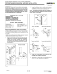
PATIODOORSYSTEMS
®
Therma-Tru
®
Fiber-Classic
and
®
Smooth-Star
Sliding Patio
Door System
Double Unit
Assembly & Installation
Read all instructions before starting.
The applicable standards for these products are governed by
the International Residential Code.
Copies of performance ratings and testing are available on our website
www.thermatru.com and our product manual.
The following packages are needed to complete the installation of your Therma-Tru®
Sliding Patio Door System. Check all components for correct size and color.
Frame Kit
1-Head Jamb
2-Side Jambs
1-Sill
1-Active Interlock
1-Inactive Interlock
1-Panel Bumper
12-#10 x 3" Flat Head Screws
12-#8 x 3" Pan Head Screws
1- This Instruction Booklet
2- Anchor Blocks
2- #10 x 1 ½" Pan Head Screws
2- #10 x 2 ½" Pan Head Screws
1-Sill Cap Base
1-Sill Cap Top
1-Drip Cap
1-Head Sealing Fin
2-Corner Pads
1-Foot Bolt
1-Foot Bolt Keeper
1-#8 x 1 ½" S.S. Pan Head Screw
2-#8 x 1" S.S. Pan Head Screws
2-Active Panel Hole Plug
3-#8 x 9/16" Pan Head Screw
1-Jamb Cover
Touch Up Paint
Handle Set Kit
2-Handles
1-Exterior Backplate
1-Interior Backplate
2-Keys
2-Handle Screws
3-Phillips Head Machine Screws
1-Allen Wrench
2-Backplate Gaskets
1-Screen (sold separately)
1-Active Panel
1-Inactive Panel
1
Active
Panel
Inactive
Panel
Additional Parts
Strike Plate
7 - #8 Flat Head Screws
Tools and materials needed for
assembly and installation:
• 100% Silicone Sealant and Caulk Gun
• 6' Level
• Measuring Tape
• Electric Drill
• #2 Phillips Drive Bit
• Staple Gun or Brad Nails
• 1/8" Drill Bit
• Phillips Head Screwdriver
• Gloves
• Safety Glasses
• Partial roll of Insulation
• Shims
• Rubber Mallet
Note: Due to ongoing product development, Therma-Tru Corp. reserves the right to make changes in
design, materials, and specifications without notice.
SCREW CHART
#8 x 9/16" S.S. Pan Head Screw
#8 x 1" S.S. Pan Head Screw
#8 x 1 3/8" Flat Head Screw
#8 x 1 ½" S.S. Pan Head Screw
#10 x 1 ½" Pan Head Screw
#10 x 2 ½ Pan Head Screw
#8 x 3" Pan Head Screw
#10 x 3" Flat Head Screw
2
Frame Assembly
NOTE:
A large work area is needed to assemble the frame kit. Cover area with
cardboard from one or more door panel cartons to protect frame parts
and floor.
1
LAY FRAME COMPONENTS ONTO WORK AREA
Lay parts on floor and position sill, head,
and side jambs with exterior side up.
Head Jamb
Side Jamb
Side Jamb
Exterior
Sill
2
IF APPLICABLE, INSTALL TOP-HUNG SCREEN
TRACK
For units using the wide profile top-hung screens, install top-hung screen track and
adapter into head jamb prior to assembly.
Reference steps 1 thru 4 of the “Wide Profile” Screen Installation - Sliding Patio
instructions, included with the top-hung screen, for complete details.
3
INSTALL SILL CAP BASE
Engage groove in sill cap base with sill.
Rotate sill cap base down to snap into place.
Use a rubber mallet if necessary.
3
Sill cap base
4
ATTACH SILL TO JAMBS
NOTE: Be sure that foam pads are in place before assembling frame.
Sealant
Sill
Jamb
Sealant
Pads
Apply sealant here
INACTIVE side ONLY
Jamb
Sill
Apply sealant to sill and side
jambs as shown.
Fasten side jambs to sill through
pre-drilled holes using (3) #10 x 3"
flat head screws. (Starting with
center screw is recommended.)
#10 x 3” flat head screw
Repeat of opposite side.
5
Sealant
ATTACH HEAD TO JAMBS
Apply sealant to end of head
jamb.
Head Jamb
Side Jamb
Fasten side jambs to head jamb
through pre-drilled holes using
(3) #10 x 3" flat head screws.
(Starting with center screw is
recommended.)
Repeat for opposite side.
Sealant
#10 x 3” flat head screw
4
6
DRIP CAP INSTALLATION
Place drip cap on top of head jamb.
Place head sealing fin on top of drip cap, engaging slot in
sealing fin with flange on drip cap.
Staple head sealing fin to each of the anchor blocks in
head jamb using 1/2" staples, nails or screws (not provided).
Head sealing fin
Drip cap
Side jamb
7
APPLY CORNER PADS TO SEALING FIN
Apply corner pads to
sealing fins at top corners.
Exterior
Corner pad
5
Frame Installation
Check rough opening as follows and correct if necessary:
• Sub-floor to be flat, level, and clean. Sill must be supported throughout
its entire length.
• All four corners to be square. Check with a framing square.
• Framing and walls to be plumb. Use a 6-foot level to check both sides
of opening.
• All wall surfaces to be straight and sides parallel.
• Opening to be correct size. Allow 3/8" on sides and ½" at head.
Wall
straight?
Check each
side both
ways.
Wall
straight?
Check all four
corners with
square.
Check floor
under sill.
6
8
APPLY SILICONE SEALANT TO SILL AND FINS
Run continuous beads of sealant
across entire length of sill bottom
and around entire perimeter of
backside of sealing fin to
provide a weather-tight seal.
Sealant
Sealant
NOTE:
CONTINUOUS BEADS OF
SEALANT ARE REQUIRED.
9
SET UNIT INTO ROUGH OPENING
Exterior
From outside of house, set system
into rough opening. Apply pressure
on sill to set sealant.
7
10 LEVEL SILL
Sill MUST be flat and level.
Check and make any necessary adjustments.
If necessary, add temporary blocking under
projecting exterior edge of sill to serve as
support during construction.
11 PLUMB SIDE JAMBS
Interior
Jambs must be plumb and straight.
Shim as necessary at screw locations
to remove any bow.
Fasten system to rough opening using
staples, nails, or screws through sealing
fin at the corners.
Fasten through every third opening in
the sealing fin.
If needed, jambs can be back
filled with insulation.
Shims
8
12 SECURE FRAME IN ROUGH OPENING
Using (12) #8 x 3" pan head screws, fasten
frame to rough opening through pre-drilled
holes in frame.
#8 x 3" Pan Head Screws
#8 x 3" Pan Head Screws
The sill does not have pre-drilled
holes. The screws used on the sill
are installed through the sill cap
base into the sill substrate. There
is a v-groove in the sill cap base
to assist in aligning the screw.
The sill's center screw needs
to be installed three inches
off center in the direction of
the active panel.
Sill Cap Base
13 APPLY SEALANT TO INACTIVE DOOR RISER
Apply a 1/4" continuous bead of clear
sealant along length of inactive sill riser
at locations shown.
Sealant
Inactive sill riser
9
14 INSTALL STATIONARY PANEL
Exterior channel
Head Jamb
From exterior side of system, install
stationary panel by inserting top of
panel up into exterior channel in head
jamb.
12
Rotate bottom of panel in until inactive
door riser leg sets into groove.
Exterior
Slide panel tightly against side jamb
Wipe off excess caulking.
As reference, the exterior side of the
panel is always the pre-finished side.
Sill
15 INSTALL ANCHOR BLOCKS
Head
Insert anchor blocks into top and
bottom of inactive door panel.
Using a 1/8" drill bit, drill through
angled “toe-screw” hole into head
and sill.
Install #10 x 2 ½" pan head screws
into “toe-screw” hole.
Fasten anchor block to panel with
#10 x 1 ½" pan head screws.
Anchor block
#10 x 2 ½" pan head screw
#10 x 1 ½" pan head screw
“toe-screw” hole
Sill
10
16 INSTALL ACTIVE PANEL
From interior side of system, install active panel up into interior
channels in head jamb. Push upwards as far as possible and rotate
into place until rollers engage sill roller track.
Head Jamb
Interior
Interior channels
17 ADJUST ROLLERS
Using a screw driver, turn adjustment
screws in rollers left or right until panel
is level and glides smoothly across the
track.
Close panel to within 1/4" of lock jamb.
Use visual margin to assure panel is
adjusted straight with frame.
11
Exterior
18 ATTACH INACTIVE INTERLOCK
Attach inactive interlock to edge of
inactive panel by butting it up into
head jamb and engaging barbs on
interlock with kerfs in door panel.
Use a wood block and hammer or
rubber mallet to tap into place.
Exterior
Inactive interlock
Inactive interlock
Kerfs
Inactive interlock
Sealant
Apply a bead of sealant along
bottom joint of inactive interlock
and sill
Sill
19 INSTALL ACTIVE INTERLOCK
Butt active interlock up against
head jamb leaving a slight gap
of approximately 1/64” between
head jamb and interlock.
Head jamb
Starting at top, insert barbs
into kerfs in door edge.
Slight gap
approx. 1/64”
Working your way down, tap
in place with a hammer and
wood block or rubber mallet.
Active interlock
Head jamb
Carefully inspect interior edge
of interlock. Tap as necessary
to obtain a tight fit along door
edge.
Active interlock
Active panel
Kerfs
Active interlock
12
20 INSERT PANEL BUMPER
Head Jamb
Insert panel bumper
into first channel from
interior in head jamb,
butting end of bumper
against stationary side
jamb. Seat panel
bumper flush
with head jamb.
Interior
Exterior
Side Jamb
Panel
Bumper
NOTE:
If needed, bumper can be cut down from its original length of 6" to 4 ½".
This will allow for a wider entrance.
21 HANDLE INSTALLATION
Refer to instructions supplied with handle set kit.
22 ATTACH STRIKE PLATE
Align slots in strike plate to pre-drilled
holes in active side jamb and fasten with
(3) #8 x 1 3/8" flat head screws.
Close door and adjust strike plate for
proper latch engagement.
Latch throw can be adjusted by the
slotted adjustment screw on the face of
mortise lock.
Pre-drill (4) 3/32" dia. pilot holes
through each screw hole of the strike
plate into the jamb.
Drive (4) #8 x 1 3/8" flat head screws
through the screw holes of the strike
plate into the jamb as shown.
13
23 PREP DOOR FOR FOOT BOLT
Tear out template on page 16 to locate and drill holes for foot bolt.
Locate template on interior side of active panel towards inactive panel side.
Align line on template with edge of active door panel and tape into place.
Drill 1/8" dia. x 1" deep holes at hole locations shown on template.
Remove template.
24 ATTACH FOOT BOLT
Align foot bolt to pre-drilled holes in active slab
and fasten with the supplied S.S. pan head sheet
metal screws included with the foot bolt
(3) #8 x 9/16" S.S. Pan Head
Sheet Metal Screws
(1) #8 x 1 ½" S.S. Pan Head
Sheet Metal Screw
Locate on bottom right corner
of the foot bolt.
25 INSTALL SILL CAP TOP
Place a continuous bead of
clear sealant, to locations
shown, along entire length
of sill cap base.
Sill cap top
Install sill cap top by
starting at each jamb and
working towards the center
of the door. Use a rubber
mallet to snap into place.
Sealant
Sill cap base
14
26 INSTALL FOOT BOLT KEEPER
Close the active door completely.
Align notch in keeper with foot bolt
as shown.
Only the two exposed holes will be
used for installation. Pre-drill using
a 1/8" drill bit to drill two holes
through the holes in the keeper into
the sill cap and through the fiberglass
of the sill.
Notch
#8 x 1” pan head
screw
Foot bolt keeper
Screw (2) #8 x 1" S.S. Pan head
sheet-metal screws into the holes.
Exposed holes
27 INSERT PLUGS
Insert supplied hole plugs
into roller adjustment holes.
Hole plug
28 ATTACH JAMB COVER
Place jamb cover on inactive
jamb with longer edge pointing
towards inactive panel. Press
into place using a rubber mallet
or a wood block and hammer.
Jamb cover
Long edge
Inactive panel
Interior
Inactive jamb
29 SLIDING SCREEN DOOR
Refer to instructions supplied with screen door.
15
Active panel edge
1/8” dia holes
1” deep
Towards
inactive
panel
Towards
inactive
panel
Bottom corner
of active panel
Bottom door edge
16
17
FINISHING INSTRUCTIONS
Work only when temperatures are between 50° and 90°F and with humidity less than 85%. Do not
finish in direct sunlight.
SMOOTH-STAR® UNITS
Painting Door Interior:
1. Clean first with mild detergent and water or use a TSP (tri-sodium phosphate) solution.
Rinse well and allow to dry completely.
2. Mask glass and hardware.
3. Use high-quality acrylic latex house paint, following manufacturer's application instructions.
4. Paint edges and exposed ends of door.
FIBER-CLASSIC® UNITS
Painting Door Interior:
1. Clean first with mild detergent and water or use a TSP (tri-sodium phosphate) solution.
Rinse well and allow to dry completely.
2. Mask glass and hardware.
3. Prime with an alkyd- or acrylic-based primer. Allow primer to dry completely.
4. Paint with an oil-based or acrylic latex house paint, following manufacturer’s application
instructions. Use a primer and paint that are compatible.
5. Paint edges and exposed ends of door.
Staining Door Interior:
We only recommend the use of the stain and clear coat products found in the Therma-Tru
Finishing System. (See the Therma-Tru Finishing System instructions for complete details.)
1. Clean first with a clean cloth and mineral spirits and allow to air dry OR wash door with a mild
detergent and water, or a TSP (tri-sodium phosphate) solution. Rinse well and allow to dry
completely.
2. Mask glass and hardware.
3. Apply stain with a cloth in a circular motion to one section at a time.
4. Wait 5-10 minutes before brushing, depending on the desire for a lighter or darker shade.
5. Brush with the natural bristle brush in the direction of the grain to “feather” or blend the stain to
a rich wood look. Clean brush tips frequently with a dry cloth to remove excess stain. Stain
and brush out each section completely before moving onto next section.
6. Allow a minimum of 48 hours drying time for the stain to cure before applying topcoat.
REPAINTING PROCEDURE
1. Sand the surface to be re-coated with 180 grit sandpaper to abrade and make porous.
2. Remove all sanding dust from the surface. This can be accomplished by using a damp cloth.
3. Optional: Wipe the surface with a solvent paint deglosser applied with a clean cloth followed
by a final wipe with an additional clean cloth to ensure the surface is free of any contaminates.
4. Apply Sherwin Williams DTM TM Bonding Primer part # B66A50 to the surface and let the
coating dry, following the directions provided on the label located on the back of the can.
5. Topcoat the Sherwin Williams DTM TM Bonding Primer with a high quality acrylic latex
coating such as Sherwin Williams SuperPaint TM A84 Series or Sherwin Williams DTM TM
Acrylic Coating B66 Series.
For store locations of the above mentioned paints call 1-800-4SHERWIN
Corresponding Sherwin Williams SuperPaint TM Codes:
BRONZE
A89T54
N1 10/32
R2 13/32
W1 39/32
B1 6Y +62/32
WHITE
A89W507
R2 1/128
B1 1/64
N1 1/64
STONE
A89W53
B1 9/32
W1 10/32
N1 2Y +46/32
ALMOND
A89W51
B1 4/32 +1/64
Y3 19/32
N1 2Y +18/32
18
WEATHERPROOF, FINISH AND MAINTAIN
• Add insulation to air space between opening and unit.
• Caulk around entire perimeter of unit on exterior side; seal sealing fins to siding
or facing, seal front bottom edge of sill, seal all joints between jamb and mouldings.
• Seal joints between exterior hardware trim and door face to prevent air and water
infiltration.
• Paint or stain according to Therma-Tru instructions. Do not paint gaskets or
weatherstrip.
• Maintain or replace sealants and finishes as soon as any deterioration is evident.
For semi-gloss or glossy paints or clear coats, do this when surface becomes dull
or rough. More severe exposures require more frequent maintenance.
• All Therma-Tru doors must be finished and maintained in accordance with our
recommendations. Failure to do so may affect the applicable warranty.
• Remove sill tape and labels on glass.
• Use touch-up paint to paint heads of rough opening screws
JAMB EXTENSION INFORMATION
The following images are intended to help clarify how a patio door is
installed in different frame openings.
The jamb extensions are made of standard wood trim materials, readily
available from lumber yards and building material retail stores.
Attach the jamb extensions through the side into the wall.
Exterior
Exterior
1 1/8”
1 1/8"
4 9/16"
6 9/16"
2 x 4 CONSTRUCTION
2”
3/4"
19
2 x 6 CONSTRUCTION
INTERIOR CASING ATTACHMENT
Interior casing may be attached to the frame in either of the following ways:
An air nailer can be used to fasten the interior casing to the frame using 0.050" x
1-½" wire brad nails through the casing and fiberglass frame. For maximum
holding power, ensure that nails are installed through anchor blocks located within
frame profiles. Locations are shown below for standard two-panel systems.
For manual application, we suggest using 4d-1-½" finish nails. They can be used
to secure interior casing to the frame. Pre-drilled pilot holes (1/16" dia.) are
recommended to avoid splitting casing or frame. Ensure that nails are installed
through anchor blocks for maximum holding power.
6 1/4”
1”
13”
6 1/4”
1”
5”
5”
31”
31”
5”
5”
20
SIZING INFORMATION
Therma-Tru Fiber-Classic/Smooth-Star Sliding Patio Specifications
Unit Size
Rough Opening
Grids
Width
Height
Width
Height
# of Lites
5/0 x R.H.
XO or OX
59 1/4
79 1/2
60
80
10 or 15
6/0 x R.H.
XO or OX
71 1/4
79 1/2
72
80
10 or 15
Description Configuration
5/0 x F.H.
6/0 x F.H.
XO or OX
XO or OX
59 1/4
71 1/4
82
82
60
72
82 1/2
82 1/2
10 or 15
10 or 15
5/0 x 8/0
6/0 x 8/0
XO or OX
XO or OX
59 1/4
71 1/4
95 1/2
95 1/2
60
72
96
96
12 or 18
12 or 18
Unit Width
R.H.
F.H.
8/0
X
O
Replacement Height
Full Height
8’ Height
Active Door
Inactive Door
Unit Height
Door Panel Information
Door Width
Fiber-Classic
Daylight
Width
Daylight
Height
Door Height
2/6 x R.H.
2/6 x F.H.
2/6 x 8/0
Door Size
Width
Height
29 1/2
76 3/16
29 1/2
78 11/16
29 1/2
92 3/16
Daylight Opening
Width
Height
20
63 1/8
20
63 1/8
19 13/16 78 13/16
3/0 x R.H.
3/0 x F.H.
3/0 x 8/0
35 1/2
35 1/2
35 1/2
26
26
23 13/16
76 3/16
78 11/16
92 3/16
63 1/8
63 1/8
78 13/16
Smooth-Star
21
Door Size
Width
Height
2/6 x R.H. 29 9/16 76 3/16
2/6 x F.H. 29 9/16 78 11/16
2/6 x 8/0 29 9/16 92 3/16
Daylight Opening
Width
Height
20
63 1/8
20
63 1/8
19 13/16 78 13/16
3/0 x R.H. 35 9/16
3/0 x F.H. 35 9/16
3/0 x 8/0 35 9/16
24 1/8
24 1/8
23 13/16
76 3/16
78 11/16
92 3/16
63 1/8
63 1/8
78 13/16
DOOR HANDING GUIDE
Right Hand
Left Hand
Viewed from exterior
22
PATIODOORSYSTEMS
1687 Woodlands Dr. Maumee, OH 43537
1-800-THERMATRU (843-7628)
www.thermatru.com
© 2005 Therma-Tru Corp.
Therma-Tru Doors is an operating company of Fortune Brands, Inc.
09/12/05
Part # FCSSSPDBL