1
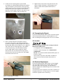
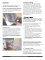
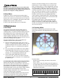
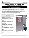
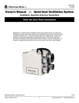
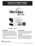
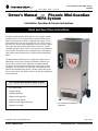
PO Box 8680 • Madison, WI 53708
Phoenix Mini-Guardian HEPA System
TS-261B
Owner’s Manual — Phoenix Mini-Guardian
HEPA System
Installation, Operation & Service Instructions
Read and Save These Instructions
The Phoenix Mini-Guardian HEPA System is the compact, variable
air speed version of our popular Phoenix Guardian HEPA System.
Maximum delivered air flow with 3-stage filtering in place is over
415 CFM and will clean one air change of a 14 x 14 foot room in
less than four minutes while drawing less than two amps of power.
This makes the Mini-Guardian HEPA System perfect for smaller
remediation projects where space is at a premium and reduced air
flow essential. A template on the intake grill makes it possible to
take air-flow measurements with the Phoenix Kestrel 3000 MultiMeter.
The Mini-Guardian HEPA System’s 3-stage filter design with true
HEPA filtration will remove virtually all hazardous particles from
the air and an optional fourth stage filter of activated carbon
and potassium permanganate will absorb a wide range of odors
and gases. The unique 24” canister HEPA, manufactured for the
Phoenix Mini-Guardian HEPA System, contains nearly 200 square
feet of surface area. This allows maximum air-flow and significantly
extends filter life.
The Phoenix Mini-Guardian HEPA System
• Less than 2 amps
• Compact design
• Variable speed flow
• Multiple ducting options
• Stainless steel cabinet
• Optional fourth stage carbon filter
Phoenix Mini-Guardian HEPA System
PN 4024774
• Wheeled cart design
Specifications subject to change without notice.
Toll-Free 1-800-533-7533
Revised 1/07
www.thermastor.com • [email protected]
1 Specifications
Table of Contents
Introduction.................................................................1
1. Specifications.........................................................1
2. Operation..............................................................1
2.1 Handle Assembly Procedure..............................1
2.2 Transporting the Phoenix Mini-Guardian HEPA
System..................................................................2
2.3 Location..........................................................2
2.4 Electrical Requirements....................................3
2.5 Air Ducting.......................................................3
2.5A Inlet Ducting.............................................3
2.5B Outlet Ducting...........................................3
2.6 Negative Air Ducting.........................................4
2.7 Power Switch...................................................4
2.8 Hour Meter......................................................5
3. Maintenance..........................................................5
3.1 Air Filters.........................................................4
3.1A Carbon/Potassium Permanganate Filter......5
3.2 Checking Airflow...............................................5
4. Service.................................................................7
4.1 Warranty..........................................................7
4.2 Impeller fan Replacement.................................7
5. Wiring Diagram......................................................8
6. Service Parts.........................................................9
7. Warranty..............................................................11
Part No.
4024774
Power
110-120 Vac, 1.96 amps; 215 watts
Blower
Up to 415 CFM (delivered air flow
w/3-stage filter operation)
Filters:1-stage 1” Spun Polyester, 16” x 16”
2-stage 2” Pleated Media, 16” x 16”
3-stage 14” dia. x 24” Canister HEPA
(optional) 4-stage 2” Carbon and Potassium Permanganate
Warranty
One Year, 100% Parts and Labor
Dimensions
Cabinet
w/Cart
Shipping
Width16”19-1/2”
20-1/2”
Height 47”
40”
40”
Depth16” 19”
20-1/2”
Weight
70 Lbs
65 Lbs
2 Operation
2.1 Handle Assembly Procedure
Tools Required: Hex Key, 8mm (Supplied with packed
parts)
1. Remove the handle assembly (consists of two handle brackets and handle tube), two metric socket head cap screws M10 x 35mm length, and 8mm hex key from the packed parts supplied with the unit.
Serial No.__________________________________
Purchase Date_____________________________
Dealer’s Name_____________________________
Read the operation and maintenance instructions
carefully before using this unit. Proper adherence to these
instructions is essential to obtain maximum benefit from
your Phoenix Mini-Guardian HEPA System.
Toll-Free 1-800-533-7533
Figure 1: Handle assembly
www.thermastor.com • [email protected]
2. Locate the two mounting holes for the handle
assembly on the Mini-Guardian HEPA System cabinet.
They are located in close proximity to the top of the
cabinet near the corners. A lock nut should be visible
through each of the mounting holes and is held in
place by a retainer plate secured to the cabinet shell.
Verify lock nut is visible in each mounting hole.
4. Tighten each of cap screws using the 8mm hex key until the handle assembly is secured against the cabinet surface and all space between parts is eliminated.
Figure 4: Tightening screws
2.2 Transporting the Phoenix
The Phoenix Mini-Guardian HEPA System should be upright
when transported by vehicle. It may be tipped on to its
back for loading and moving by hand or for use on location.
Figure 2: Mounting holes
2.3 Location
3. Place a socket head cap screw (M10 x 35mm) into each of the holes in the handle end brackets. Position the handle assembly up against the Phoenix
Mini-Guardian HEPA System cabinet so as to align the
cap screws with the mounting holes in the cabinet.
It may be necessary to tilt the handle assembly up at a slight angle in order to align the screws with the lock nuts. Use the 8mm hex key to press the cap screws into the mounting holes and engage
the threads of the lock nuts.
Note the following precautions when locating the Phoenix
Mini-Guardian HEPA System:
· It is designed to be used INDOORS ONLY.
· If used in a wet area, plug it into a GROUND FAULT
INTERRUPTER.
· DO NOT use the Phoenix Mini-Guardian HEPA System as
a bench or table.
· The air inlet on top & the side outlets should be at least 1 foot from walls and other obstructions to airflow.
2.4 Electrical Requirements
The Phoenix Mini-Guardian HEPA System can be plugged
into a grounded 15 Amp circuit. It draws about 2 Amps
with clean filters and no ducting. The amp draw will
decrease slightly with added ducting and as the filters load
with particulate.
If an extension cord is required, it must have a minimum of
18 gauge conductors if 25 feet long or less and 16 gauge
conductors if greater than 25 feet long.
Figure 3: Handle tilting for assembly
Toll-Free 1-800-533-7533
www.thermastor.com • [email protected]
2.5 Air Ducting
2.6 Negative Air Ducting
2.5A Inlet Ducting
Occasionally the area to be filtered is difficult to access
and/or the unit cannot be located in the area. In such
cases, the air can be ducted to the unit’s inlet.
A round 12” diameter flexible duct can be attached to the
unit inlet on top. It connects by placing the wire in the duct
under the four tabs on the top. It may be removed after
use for easier transport and storage. Flexible 12” duct is
available from Therma-Stor LLC.
The Phoenix Mini-Guardian HEPA System can be used
to filter and exhaust air from a space. By exhausting
to outside the space, the space will be under a slight
negative pressure. This will help prevent airborne particles
from leaving the space, since the negative pressure will
draw air in through openings in the space’s exterior.
The quantity of air exhausted depends on how the unit is
ducted and what speed is used. A duct can be directed
outside. Cover the other exhaust openings to direct all the
filtered air outside. This would result in up to 400 CFM
being exhausted on high speed and an equal amount of
fresh air being drawn in.
CAUTION: Exhausting too much air from a space with open
combustion devices (e.g. furnace, fireplace or water heater)
can cause those devices to backdraft. This can contaminate
the space with potentially fatal gases.
In such cases, the Phoenix Mini-Guardian HEPA System
must be used in one of the following three ways:
A. As a filtering unit only. Exhausting no air from the space and thus causing no negative pressure or backdrafting.
B. Exhausting a very limited amount of air which does not
cause backdrafting. In case B, the open combustion
devices must be thoroughly checked to guarantee that
they do not backdraft while the Phoenix Mini-Guardian
HEPA System is running.
C. Direct the outlet duct from the Mini-Guardian HEPA
System to the room with the open combustion
device(s). This will positively pressurize the room,
thus preventing backdrafting. As in case B, those
combustion devices must be checked after the MiniGuardian HEPA System is running to guarantee that
they are not backdrafting.
Figure 5: Inlet ducting
2.5B Outlet Ducting
A detachable rectangular exhaust collar is supplied that
will allow 10” round lay-flat plastic duct to be attached to
the Phoenix Mini-Guardian HEPA System outlet. Lay-flat
plastic ducting is available from Therma-Stor LLC.
To attach ducting to a collar, remove the collar from the
unit by sliding the collar upward out of the guide. Put
the plastic duct end through the collar center. Roll the
duct end outward so that it over-laps the outside of the
collar. The duct will hook over the collar, preventing it from
slipping off.
The duct can be directed outside, exhausting a portion of
the filtered air. The rest of the filtered air is recirculated
inside the space. Blocking the other supply holes will
determine the amount of air that is exhausted. By
adjusting the blocking plates over the supply openings, the
quantity exhausted can be adjusted down to no flow.
2.7 Power/Speed Control
The power/speed switch is located in the recessed cavity
on the unit front. When turned on to any speed, it powers
the impeller fan and hour meter.
Occasionally the impeller fan may not start on low speed.
If this occurs, rotate the speed control to high speed until
the impeller fan starts, then adjust it to a lower speed.
Figure 6: Outlet ducting
Toll-Free 1-800-533-7533
www.thermastor.com • [email protected]
that part of the blend changes color as it loads up with
contaminants. It starts out black, then turns pink, then
brown, and finally white. It is best changed when it passes
the brown stage and begins to turn white. It has lost most
of its effectiveness at that point. When these filters are
installed, the pad filter does not need to be installed above
them. This allows the operator to check the media color
through the top grill of the unit without removing the top.
The filter is the same size as the pleated fabric filter.
Install it above the pleated fabric filter. The pleated fabric
filter catches carbon dust that comes off the carbon filter
before it reaches the HEPA filter.
The refillable carbon filter is metal-framed and can be
refilled with carbon blend media purchased in 5-gallon
buckets. The amount of carbon blend media loaded into
the filter can be adjusted to the particular amount of gas/
odor removal required.
CAUTION: Do not remove the top to access the filters with
the unit on. Removing the top and filters while running can:
(A) expose potentially fatal high voltage electrical parts, and
(B) expose the dangerous rotating impeller fan.
2.8 Hour Meter
A digital hour meter is located near the power/speed
control on the unit front. It measures the cumulative time
that the unit is turned on to tenths of an hour. It stores its
total when the unit is unplugged. The previous total will be
displayed when the unit is next turned on.
It resets to zero after 99,999.9 hours of operation.
3 Maintenance
3.2 Checking Airflow
3.1 Air Filters
The airflow is checked using a Phoenix Kestrel 3000
airflow meter placed on the designated area on the top of
the unit.
The standard Phoenix Mini-Guardian HEPA System is
equipped with three filters that progressively filter out
smaller particles. An optional activated carbon/potassium
permanganate filter can be used, giving a fourth stage
of filter media (see Section 3.1A). These filters must be
checked regularly. Operating the unit with dirty filters will
reduce the airflow, but will do no harm to the unit. The unit
can be run indefinitely with dirty filters.
The three standard filters used are listed below (as
installed in the unit from top to bottom):
A. Polyester media pad pre-filter. Actual size 15-3/4” x
15-3/4” x 1” thick. The white side faces up. This filter
should be replaced when the airflow is reduced, it is
visibly dirty or when it is contaminated by a previous
job.
B. 25 to 30% efficient (per ASHRAE 52.1-1992), MERV-7, pleated fabric filter. Actual size is 15-3/4” x 15-3/4” x 1-3/4”. This filter should be changed when airflow is
reduced or it is contaminated by a previous job.
C. 99.97% DOP efficient HEPA filter. Actual size is
13-7/8” OD x 24” x 8-7/8” ID. This filter should be
changed when airflow is reduced or it is contaminated
by a previous job.
Figure 7: Checking airflow
To check airflow:
· Remove any inlet ducting, but leave the top and all
filters in place.
· Turn the unit on high. The airflow meter will indicate an
air speed. Please set the air meter to read FPM (refer to
the meter instructions to set the mode). To determine
CFM see the chart below:
3.1A Activated Carbon/Potassium Permanganate Filters
Optional gas phase filters are available from ThermaStor. They use a blend of activated carbon and potassium
permanganate. This blend removes the vast majority of
contaminants encountered in most filtering applications.
The activated carbon removes the heavier volatile organics
while the potassium permanganate removes lower
molecular weight contaminants. This is well suited to the
smoke odors present after fire damage.
The life of the media blend depends upon both the hours
used and the contamination level. Another advantage
of the blended media versus activated carbon only is
Toll-Free 1-800-533-7533
Kestrel 3000 FPM
700 650 600 550 500 450 400 350 300 250 200 150
400 371 343 320 286 263 235 208 182 153 120 87
CFM
www.thermastor.com • [email protected]
Airflow on high speed with all filters clean and no ducting
is about 400 CFM. The unit can be run with very dirty
filters and virtually no flow without harming the unit. The
operator’s decision to change filters should be based on
filter cost vs. the unit’s filtering effectiveness. If airflow is
200 CFM vs. 400 CFM, the unit will filter particles from a
space at half the rate. The operator must judge if that is
acceptable.
If the operator determines the filters should be changed
due to low airflow, it is most economical to change them in
the following order:
Change the pad pre-filter (top) first. This is the least
expensive filter. Recheck the airflow. If the airflow is
acceptable, no other filters need to be changed.
Change the pleated fabric filter (middle) second. It is the
second least expensive filter. Recheck the airflow.
If acceptable, the HEPA filter does not need changing.
If the airflow is still too low, the HEPA filter must be
changed. To remove the HEPA filter, follow these steps:
1. Loosen the two 3/8” thumbscrews that secure the HEPA filter.
3. Disengage the screw and spacer from the hole in the front of the cabinet and remove the filter holddown bar.
Figure 10: Disengage screw and spacer
4. Lift the old filter straight up and out of the cabinet.
Place the new HEPA filter with the open side down, into the cabinet. Be sure the four bumpers on the base center it.
Figure 8: Loosen thumb screws
2. Push down on the filter hold-down bar and out on the back of the cabinet to disengage the two “ears” from the back of the cabinet. Rock the filter hold-down bar up towards the front of the cabinet.
Figure 11: Lift filter straight up
Figure 9: Push down on the filter hold-down bar
Toll-Free 1-800-533-7533
www.thermastor.com • [email protected]
4 Service
4. Remove the cable clamp holding the impeller fan cable
and ground terminals. Remove the ground wire from
the mounting screw. Disconnect the black and brown
wires from the run capacitor, and cut the blue wire
near the wire nut.
CAUTION: Servicing the Phoenix Mini-Guardian HEPA
System with its high voltage circuitry presents a health
hazard that could result in death, serious bodily injury, and/
or property damage. Only qualified service people should
service this unit.
4.1 Warranty
A warranty certificate has been enclosed with this unit.
Read it before any repair is initiated. If a warranty repair
is required, call the factory first at 1-800-533-7533 for
warranty claim authorization and technical assistance.
Clamp
Cable
4.2 Impeller Fan Replacement
Cut near
wire nut
Occasionally the impeller fan may not start on low speed. If
this occurs, rotate the speed control to high speed until the
impeller fan starts, then adjust it to low speed.
Figure 13: Remove cable clamp
5. Remove the 1/4” machine screws holding the base to the cabinet. Remove the base from the cabinet.
6. Remove the four 4 mm machine screws that hold the motor to the lower base. Remove the cable clamp that holds the impeller fan cable to the bottom of the base.
Follow the steps below to change the impeller fan:
1. Unplug the power cord.
2. Remove the top and all air filters.
3. Remove the rear electrical guard held inside the unit by four mm machine screws and nuts.
Clamp
cable
inside
4 mm
screws
Figure 14: Remove screws
Figure 12: Remove guard
7. Remove the strain relief
bushing holding the
impeller fan cable in the
top of the base.
Figure 15: Remove strain relief
Toll-Free 1-800-533-7533
www.thermastor.com • [email protected]
8. Using a pliers, twist the tabs of the base supports to align with the slots. Remove only one of the base supports (see below). Spread the base apart slightly to remove the impeller fan.
Twist
tabs
9. Remove the four 4 mm machine screws and lock washers securing the impeller fan.
10.Reverse this procedure to reassemble with the new impeller fan.
Remove
one of
these
base
supports
Figure 16: Twist tabs
Figure 17: Electrical schematic
Toll-Free 1-800-533-7533
www.thermastor.com • [email protected]
5 Service Parts
Item Part No.
Qty.
1
40248241
2
40217991
3
40246671
4
40248301
5
40246841
6
40247731
7
40248251
8
4024820
4
9
4022465
6
10
40247751
11
4024073
2
12
40260931
13
40215971
14
40217001
15
40246921
16
4024070
2
17
40240781
18
40248221
19
4024827
6
20
4024828
2
21
4024066
2
22
4024821
2
Description
Air Filter, Polyester, 1” x 16” x 16”
Air Filter, Pleated, 2” x 16” x 16”
Air Filter, HEPA, 14” OD x 24”
(99.97% Efficient)
Axle
Impeller Fan
Impeller Fan Speed Control
Impeller Fan Speed Control Knob
Bumper (.59 Dia. X .35 High)
Bumper (1.13 Dia. x 1” High)
Cord & Wire Harness
Foot
Handle Assembly
Hour Meter
Pocket Handle
Run Capacitor, 20 mfd, 370 VAC
Outlet Cover, Side
Outlet Duct Collar
Outlet Cover/Guard, Rear
Thumb Screw, 1/4”
Thumb Screw, 3/8”
Wheel, 5”, Plastic
Wheel Center Cap
Optional Parts
4021950
4024879
4024891
4024528
4024750
4022537
4024440
Ground Fault Interrupter
Air Filter, Disposable Carbon/
Potassium Permanganate
Air Filter, Refillable Carbon/
Potassium Permanganate
Carbon/Potassium Permanganate,
5 gal Pail
Duct, Flex, 12” x 25’
Duct, Lay Flat, 10” x 500’
Kestrel 3000 Weather Meter
Specifications subject to change without notice.
Toll-Free 1-800-533-7533
www.thermastor.com • [email protected]
This page intentionally left blank.
Toll-Free 1-800-533-7533
10
www.thermastor.com • [email protected]
Phoenix Mini-Guardian HEPA System Limited Warranty
Warrantor:
Therma-Stor LLC
PO Box 8680
Madison, WI 53708
Telephone: 1-800-533-7533
Who Is Covered: This warranty extends only to the original end-user of the Mini-Guardian HEPA
System, and may not be assigned or transferred.
First Year Warranty: Therma-Stor Products warrants that, for one (1) year the Mini-Guardian HEPA
System will operate free from any defects in materials and workmanship, or Therma-Stor Products
will, at its option, repair or replace the defective part(s), free of any charge.
End-User Responsibilities: Warranty service must be performed by a Servicer authorized by ThermaStor Products. If the end-user is unable to locate or obtain warranty service from an authorized
Servicer, he should call Therma-Stor Products at the above number and ask for the Therma-Stor
Products Service Department, which will then arrange for covered warranty service. Warranty service
will be performed during normal working hours.
The end-user must present proof of purchase (lease) upon request, by use of the warranty card or
other reasonable and reliable means. The end-user is responsible for normal care. This warranty
does not cover any defect, malfunction, etc. resulting from misuse, abuse, lack of normal care,
corrosion, freezing, tampering, modification, unauthorized or improper repair or installation, accident,
acts of nature or any other cause beyond Therma-Stor Products’ reasonable control.
Limitations and Exclusions: If any Mini-Guardian HEPA System part is repaired or replaced, the new
part shall be warranted for only the remainder of the original warranty period applicable thereto (but
all warranty periods will be extended by the period of time, if any, that the Mini-Guardian HEPA System
is out of service while awaiting covered warranty service).
UPON THE EXPIRATION OF THE WRITTEN WARRANTY APPLICABLE TO THE Mini-Guardian HEPA System
OR ANY PART THEREOF, ALL OTHER WARRANTIES IMPLIED BY LAW, INCLUDING MERCHANTABILITY
AND FITNESS FOR A PARTICULAR PURPOSE, SHALL ALSO EXPIRE. ALL WARRANTIES MADE BY
THERMA-STOR PRODUCTS ARE SET FORTH HEREIN, AND NO CLAIM MAY BE MADE AGAINST THERMASTOR PRODUCTS BASED ON ANY ORAL WARRANTY. IN NO EVENT SHALL THERMA-STOR PRODUCTS,
IN CONNECTION WITH THE SALE, INSTALLATION, USE, REPAIR OR REPLACEMENT OF ANY MiniGuardian HEPA System OR PART THEREOF BE LIABLE UNDER ANY LEGAL THEORY FOR ANY SPECIAL,
INDIRECT OR CONSEQUENTIAL DAMAGES INCLUDING WITHOUT LIMITATION WATER DAMAGE (THE
END-USER SHOULD TAKE PRECAUTIONS AGAINST SAME), LOST PROFITS, DELAY, OR LOSS OF USE
OR DAMAGE TO ANY REAL OR PERSONAL PROPERTY.
Some states do not allow limitations on how long an implied warranty lasts, and some do not
allow the exclusion or limitation of incidental or consequential damages, so one or both of these
limitations may not apply to you.
Legal Rights: This warranty gives you specific legal rights, and you may also have other rights which
vary from state to state.
TS-237
Toll-Free 1-800-533-7533
11
www.thermastor.com • [email protected]