1
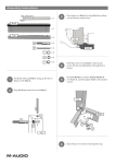
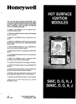
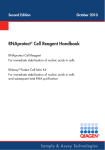
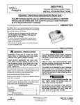
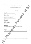
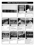
S210® Wiring Block Instructions
1
S210 Wall Mount
Mount the S210™ wiring base
and legs onto a suitable mounting
surface with the necessary screws
and hardware.
Remove the S210 wiring
base from the legs by
depressing the outer 4 fanning strips
of the S210 wiring base inward to
defeat the leg latches. Pull the
wiring base away from the legs.
2
Note: Legs are detachable on the
64-pair version only.
With the S210 base
removed, route the cable
between the legs.
3
Lace the cables through the
appropriate openings in the
wiring base and snap the S210 wiring
base back onto the legs. Push the
wiring base onto the legs until the
latches “snap” into place. Proceed to
step 9 for terminating instructions.
4
5
S210 Rack Mount
9
S210 Wiring Block
Mount S210 19 inch panel
onto the rack using the #12-24
screws and washers provided.
Lace the cables through the
appropriate openings in the
S210 base. Proceed to step 9 for terminating instructions.
6
Note: For additional security, the assembly
can be fastened together using the selftapping, Phillips-head screws included.
7
S210 S89
Retainer Mount
Mount S89B or S89D bracket onto a
suitable mounting surface with the
necessary screws and hardware.
Route the cable through the center
channel of the bracket.
Lace the cables through the
center hole of the S210™ 89
retainer and snap the retainer onto
the S89 bracket. Proceed to step 9
for terminating instructions.
8
Strip back only as much cable
jacket as is necessary to terminate
the conductors using the Siemon
AllPrep™ Cable Preparation Tool
(P/N: CPT-RGTP) or equivalent.
Note: It is not recommended to strip
more than 76mm (3 in.) of cable jacket for
category 5 or higher installations.
Lace the conductors into the
S210 wiring base. Pair twist
must be maintained to within 12mm
(.5 in.) of the point of termination for
category 5 or higher installations.
Ample channel space is provided to
allow jacketed cable to continue
close to the point of termination.
10
Note: The Pyramid™ wire entry system on the
base and block will separate twisted conductors without special preparations or handling.
S210 Wiring Block Instructions
Seat the conductors and trim
off the excess wire with the
cutting edge of the Siemon S210
Multi-Pair Termination Tool (P/N:
S788J4-210) or equivalent.
11
Visually inspect the conductor and cable placement to
eliminate miswires or reversals.
12
Insert a connecting block
(P/N: S210C-4) into the head
of the Siemon termination tool.
13
Carefully align the connecting
block over the wiring base
with the blue marking to the left side
of the block (printed side down) and
seat the connecting block.
14
NOTE: Be sure that the cutting edge is
properly oriented prior to trimming the wire.
Label the circuits then slide
the designation strip into the
label holder (P/N: S210-HLDR) and
snap the holder onto the wiring
base. Complete the connections
using CJ5 series cross-connect wire
or patch cables.
15
The Siemon vertical wire
manager (P/N: S100A2) can
be ordered separately and mounted to
the legs of the S210 block to provide
vertical cable management for S210
patch cords or cross-connect wire.
16
17
S210 Patch Plug
Position plug with icon
pocket on top when mating with
S210 connecting block.
NOTE: Remove designation strips prior to
removing base from legs.
To assist safe installations, comply with the following:
B. Never touch uninsulated wire terminals unless
the circuit has been disconnected.
C. Never install this device in a wet location.
D. Never install wiring during a lightning storm.
Global Headquarters
Watertown, Connecticut USA
Tel: (1) 866-548-5814
For a complete listing of our global offices visit our web site
www.siemon.com
© 2007 Siemon
Rev. C 07/07 100.6634
A. Use caution when installing or modifying
telecommunications circuits.