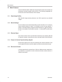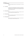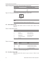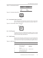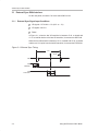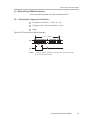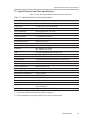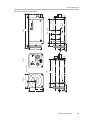
1
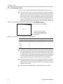
MC-780PIx CCD Camera User’s Guide SOCU006 July 1998 Printed on Recycled Paper IMPORTANT NOTICE Texas Instruments and its subsidiaries (TI) reserve the right to make changes to their products or to discontinue any product or service without notice, and advise customers to obtain the latest version of relevant information to verify, before placing orders, that information being relied on is current and complete. All products are sold subject to the terms and conditions of sale supplied at the time of order acknowledgement, including those pertaining to warranty, patent infringement, and limitation of liability. TI warrants performance of its semiconductor products to the specifications applicable at the time of sale in accordance with TI’s standard warranty. Testing and other quality control techniques are utilized to the extent TI deems necessary to support this warranty. Specific testing of all parameters of each device is not necessarily performed, except those mandated by government requirements. CERTAIN APPLICATIONS USING SEMICONDUCTOR PRODUCTS MAY INVOLVE POTENTIAL RISKS OF DEATH, PERSONAL INJURY, OR SEVERE PROPERTY OR ENVIRONMENTAL DAMAGE (“CRITICAL APPLICATIONS”). TI SEMICONDUCTOR PRODUCTS ARE NOT DESIGNED, AUTHORIZED, OR WARRANTED TO BE SUITABLE FOR USE IN LIFE-SUPPORT DEVICES OR SYSTEMS OR OTHER CRITICAL APPLICATIONS. INCLUSION OF TI PRODUCTS IN SUCH APPLICATIONS IS UNDERSTOOD TO BE FULLY AT THE CUSTOMER’S RISK. In order to minimize risks associated with the customer’s applications, adequate design and operating safeguards must be provided by the customer to minimize inherent or procedural hazards. TI assumes no liability for applications assistance or customer product design. TI does not warrant or represent that any license, either express or implied, is granted under any patent right, copyright, mask work right, or other intellectual property right of TI covering or relating to any combination, machine, or process in which such semiconductor products or services might be or are used. TI’s publication of information regarding any third party’s products or services does not constitute TI’s approval, warranty or endorsement thereof. Copyright 1998, Texas Instruments Incorporated Information About Cautions and Warnings Preface Read This First About This Manual This User’s Guide describes the characteristics and operation of the MC-780PIA and MC-780PIH CCD Video Camera Modules. How to Use This Manual Use this manual for technical data, operating characteristics, and general familiarization with the products before, during, and after installation. Information About Cautions and Warnings This book may contain cautions and warnings. This is an example of a caution statement. A caution statement describes a situation that could potentially damage your software or equipment. This is an example of a warning statement. A warning statement describes a situation that could potentially cause harm to you. The information in a caution or a warning is provided for your protection. Please read each caution and warning carefully. Read This First iii If You Need Assistance If You Need Assistance . . . If you want to . . . Contact Texas Instruments at . . . Visit TI online World Wide Web: http://www.ti.com Receive general information or assistance World Wide Web: http://www.ti.com/sc/docs/pic/home.htm North America, South America: (214) 644–5580 Europe, Middle East, Africa Dutch: English: French: Italian: German: 33–1–3070–1166 33–1–3070–1165 33–1–3070–1164 33–1–3070–1167 33–1–3070–1168 Japan (Japanese or English) Domestic toll-free: 0120–81–0026 International: 81–3–3457–0972 or 81–3–3457–0976 Korea (Korean or English): 82–2–551–2804 Taiwan (Chinese or English): 886–2–3771450 Ask questions about Digital Signal Processor (DSP) product operation or report suspected problems Ask questions about microcontroller product operation or report suspected problems Request tool updates Order Texas Instruments documentation (see Note 1) Make suggestions about or report errors in documentation (see Note 2) Notes: Fax: Fax Europe: Email: World Wide Web: BBS North America: BBS Europe: 320 BBS Online: Fax: Email: World Wide Web: BBS: (713) 274–2320 (713) 274–2324 +33–1–3070–1032 [email protected] http://www.ti.com/dsps (713) 274–2323 8–N–1 +44–2–3422–3248 ftp.ti.com:/mirrors/tms320bbs (192.94.94.53) (713) 274–2370 (713) 274–4203 *[email protected] http://www.ti.com/sc/micro (713) 274–3700 8–N–1 Software: (214) 638–0333 Software fax: (214) 638–7742 Hardware: (713) 274–2285 Literature Response Center: (800) 477–8924 Email: [email protected] Mail: Texas Instruments Incorporated Technical Publications Manager, MS 702 P.O. Box 1443 Houston, Texas 77251–1443 1) The literature number for the book is required; see the lower-right corner on the back cover. 2) Please mention the full title of the book, the literature number from the lower-right corner of the back cover, and the publication date from the spine or front cover. iv Running Title—Attribute Reference Contents 1 Overview . . . . . . . . . . . . . . . . . . . . . . . . . . . . . . . . . . . . . . . . . . . . . . . . . . . . . . . . . . . . . . . . . . . . . . . . 1.1 Main Features . . . . . . . . . . . . . . . . . . . . . . . . . . . . . . . . . . . . . . . . . . . . . . . . . . . . . . . . . . . . . . 1.1.1 High Image Quality . . . . . . . . . . . . . . . . . . . . . . . . . . . . . . . . . . . . . . . . . . . . . . . . . . 1.1.2 Mode Settings . . . . . . . . . . . . . . . . . . . . . . . . . . . . . . . . . . . . . . . . . . . . . . . . . . . . . . 1.1.3 External Sync . . . . . . . . . . . . . . . . . . . . . . . . . . . . . . . . . . . . . . . . . . . . . . . . . . . . . . . 1.1.4 Output of Internal Synchronizing Signals . . . . . . . . . . . . . . . . . . . . . . . . . . . . . . . 1.1.5 Electronic Shutter . . . . . . . . . . . . . . . . . . . . . . . . . . . . . . . . . . . . . . . . . . . . . . . . . . . 1.2 Other Features . . . . . . . . . . . . . . . . . . . . . . . . . . . . . . . . . . . . . . . . . . . . . . . . . . . . . . . . . . . . . 2 Nomenclature and Use of Each Component . . . . . . . . . . . . . . . . . . . . . . . . . . . . . . . . . . . . . . . 2-1 2.1 Mounting System . . . . . . . . . . . . . . . . . . . . . . . . . . . . . . . . . . . . . . . . . . . . . . . . . . . . . . . . . . . 2-2 2.1.1 Focus Ring . . . . . . . . . . . . . . . . . . . . . . . . . . . . . . . . . . . . . . . . . . . . . . . . . . . . . . . . . 2-2 2.1.2 Mounting Holes A . . . . . . . . . . . . . . . . . . . . . . . . . . . . . . . . . . . . . . . . . . . . . . . . . . . 2-2 2.1.3 Mounting Hole B . . . . . . . . . . . . . . . . . . . . . . . . . . . . . . . . . . . . . . . . . . . . . . . . . . . . 2-2 2.1.4 Mounting Holes C . . . . . . . . . . . . . . . . . . . . . . . . . . . . . . . . . . . . . . . . . . . . . . . . . . . 2-2 2.2 Rear Panel Switches and Terminals . . . . . . . . . . . . . . . . . . . . . . . . . . . . . . . . . . . . . . . . . . . 2-3 2.2.1 Shutter Speed Control Switch SW1 . . . . . . . . . . . . . . . . . . . . . . . . . . . . . . . . . . . . 2-3 2.2.2 External Synchronization Terminal Resistance Switch SW4 . . . . . . . . . . . . . . . 2-4 2.2.3 Mode Switches SW3 . . . . . . . . . . . . . . . . . . . . . . . . . . . . . . . . . . . . . . . . . . . . . . . . . 2-4 2.2.4 Gain Mode Switch SW2 . . . . . . . . . . . . . . . . . . . . . . . . . . . . . . . . . . . . . . . . . . . . . . 2-5 2.2.5 Gain Variable Volume Control VR1 . . . . . . . . . . . . . . . . . . . . . . . . . . . . . . . . . . . . . 2-5 2.2.6 DC IN Terminal . . . . . . . . . . . . . . . . . . . . . . . . . . . . . . . . . . . . . . . . . . . . . . . . . . . . . . 2-6 2.2.7 LENS Terminal . . . . . . . . . . . . . . . . . . . . . . . . . . . . . . . . . . . . . . . . . . . . . . . . . . . . . . 2-6 2.2.8 DC IN/SYNC Terminal . . . . . . . . . . . . . . . . . . . . . . . . . . . . . . . . . . . . . . . . . . . . . . . . 2-6 2.3 Internal Switches . . . . . . . . . . . . . . . . . . . . . . . . . . . . . . . . . . . . . . . . . . . . . . . . . . . . . . . . . . . 2-8 2.3.1 SYNC Signal (HD/VD) Input/Output Switch SW1 . . . . . . . . . . . . . . . . . . . . . . . . . 2-8 2.3.2 Option Output Switch S1 . . . . . . . . . . . . . . . . . . . . . . . . . . . . . . . . . . . . . . . . . . . . . 2-9 2.3.3 Gamma Switch SW1 . . . . . . . . . . . . . . . . . . . . . . . . . . . . . . . . . . . . . . . . . . . . . . . . . 2-9 2.3.4 AC/DC Output Switch SW4 . . . . . . . . . . . . . . . . . . . . . . . . . . . . . . . . . . . . . . . . . . 2-10 2.3.5 Outline Emphasis Circuit ON/OFF Switch SW2 . . . . . . . . . . . . . . . . . . . . . . . . . 2-10 3 Using the External SYNC Mode . . . . . . . . . . . . . . . . . . . . . . . . . . . . . . . . . . . . . . . . . . . . . . . . . . . 3.1 External Sync With Interlace . . . . . . . . . . . . . . . . . . . . . . . . . . . . . . . . . . . . . . . . . . . . . . . . . 3.1.1 External Sync Signal Input Conditions . . . . . . . . . . . . . . . . . . . . . . . . . . . . . . . . . . 3.2 External Sync With No Interlace . . . . . . . . . . . . . . . . . . . . . . . . . . . . . . . . . . . . . . . . . . . . . . 3.2.1 External Sync Signal Input Conditions . . . . . . . . . . . . . . . . . . . . . . . . . . . . . . . . . . 4 Using the Shutter Modes . . . . . . . . . . . . . . . . . . . . . . . . . . . . . . . . . . . . . . . . . . . . . . . . . . . . . . . . . 4-1 4.1 Continuous Shutter . . . . . . . . . . . . . . . . . . . . . . . . . . . . . . . . . . . . . . . . . . . . . . . . . . . . . . . . . 4-2 Chapter Title—Attribute Reference 1-1 1-2 1-2 1-2 1-2 1-2 1-2 1-3 3-1 3-2 3-2 3-3 3-3 v Contents 4.2 4.3 4.4 4.5 Random Shutter (Fixed V Sync) . . . . . . . . . . . . . . . . . . . . . . . . . . . . . . . . . . . . . . . . . . . . . . Random Shutter (V Sync Reset) . . . . . . . . . . . . . . . . . . . . . . . . . . . . . . . . . . . . . . . . . . . . . . VI Mode Shutter . . . . . . . . . . . . . . . . . . . . . . . . . . . . . . . . . . . . . . . . . . . . . . . . . . . . . . . . . . . . Precautionary Items . . . . . . . . . . . . . . . . . . . . . . . . . . . . . . . . . . . . . . . . . . . . . . . . . . . . . . . . . 4-3 4-4 4-5 4-6 5 Initial Settings . . . . . . . . . . . . . . . . . . . . . . . . . . . . . . . . . . . . . . . . . . . . . . . . . . . . . . . . . . . . . . . . . . . 5-1 5.1 Modes and Initial Switch Settings . . . . . . . . . . . . . . . . . . . . . . . . . . . . . . . . . . . . . . . . . . . . . 5-2 6 Precautions for Use . . . . . . . . . . . . . . . . . . . . . . . . . . . . . . . . . . . . . . . . . . . . . . . . . . . . . . . . . . . . . 6.1 Precautions for Use . . . . . . . . . . . . . . . . . . . . . . . . . . . . . . . . . . . . . . . . . . . . . . . . . . . . . . . . . 6.1.1 Power Source . . . . . . . . . . . . . . . . . . . . . . . . . . . . . . . . . . . . . . . . . . . . . . . . . . . . . . . 6.1.2 Heat Reduction . . . . . . . . . . . . . . . . . . . . . . . . . . . . . . . . . . . . . . . . . . . . . . . . . . . . . 6.1.3 Locations for Use and Storage . . . . . . . . . . . . . . . . . . . . . . . . . . . . . . . . . . . . . . . . 6.2 Maintenance . . . . . . . . . . . . . . . . . . . . . . . . . . . . . . . . . . . . . . . . . . . . . . . . . . . . . . . . . . . . . . . 7 Specifications . . . . . . . . . . . . . . . . . . . . . . . . . . . . . . . . . . . . . . . . . . . . . . . . . . . . . . . . . . . . . . . . . . . 7-1 7.1 Image System . . . . . . . . . . . . . . . . . . . . . . . . . . . . . . . . . . . . . . . . . . . . . . . . . . . . . . . . . . . . . . 7-2 7.2 Optical Elements and Other Specifications . . . . . . . . . . . . . . . . . . . . . . . . . . . . . . . . . . . . . 7-3 8 Exterior Dimensions . . . . . . . . . . . . . . . . . . . . . . . . . . . . . . . . . . . . . . . . . . . . . . . . . . . . . . . . . . . . . 8-1 8.1 Exterior Dimensions . . . . . . . . . . . . . . . . . . . . . . . . . . . . . . . . . . . . . . . . . . . . . . . . . . . . . . . . 8-2 9 Other Issues . . . . . . . . . . . . . . . . . . . . . . . . . . . . . . . . . . . . . . . . . . . . . . . . . . . . . . . . . . . . . . . . . . . . 9-1 9.1 Connectors . . . . . . . . . . . . . . . . . . . . . . . . . . . . . . . . . . . . . . . . . . . . . . . . . . . . . . . . . . . . . . . . 9-2 vi 6-1 6-2 6-2 6-2 6-2 6-3 Illustrations Figures 2–1 2–2 2–3 2–4 2–5 2–6 2–7 2–8 2–9 2–10 3–1 3–2 4–1 4–2 4–3 4–4 4–5 8–1 Rear Panel . . . . . . . . . . . . . . . . . . . . . . . . . . . . . . . . . . . . . . . . . . . . . . . . . . . . . . . . . . . . . . . . . . . 2-3 External Synchronization Terminal Resistance Switch SW4 . . . . . . . . . . . . . . . . . . . . . . . . . 2-4 Gain Mode Switch SW2 . . . . . . . . . . . . . . . . . . . . . . . . . . . . . . . . . . . . . . . . . . . . . . . . . . . . . . . . 2-5 Gain Variable Volume Control VR1 . . . . . . . . . . . . . . . . . . . . . . . . . . . . . . . . . . . . . . . . . . . . . . 2-5 Internal Switches . . . . . . . . . . . . . . . . . . . . . . . . . . . . . . . . . . . . . . . . . . . . . . . . . . . . . . . . . . . . . . 2-8 SYNC Signal (HD/VD) Input/Output Switch SW1 . . . . . . . . . . . . . . . . . . . . . . . . . . . . . . . . . . 2-9 Option Output Switch S1 . . . . . . . . . . . . . . . . . . . . . . . . . . . . . . . . . . . . . . . . . . . . . . . . . . . . . . . 2-9 Gamma Switch SW1 . . . . . . . . . . . . . . . . . . . . . . . . . . . . . . . . . . . . . . . . . . . . . . . . . . . . . . . . . . 2-9 AC/DC Output Switch SW4 . . . . . . . . . . . . . . . . . . . . . . . . . . . . . . . . . . . . . . . . . . . . . . . . . . . . 2-10 Outline Emphasis Circuit ON/OFF Switch SW2 . . . . . . . . . . . . . . . . . . . . . . . . . . . . . . . . . . 2-10 External Sync Timing . . . . . . . . . . . . . . . . . . . . . . . . . . . . . . . . . . . . . . . . . . . . . . . . . . . . . . . . . . 3-2 External Sync With No Interlace . . . . . . . . . . . . . . . . . . . . . . . . . . . . . . . . . . . . . . . . . . . . . . . . . 3-3 Continuous Shutter Speed-Control Timing . . . . . . . . . . . . . . . . . . . . . . . . . . . . . . . . . . . . . . . . 4-2 Random Shutter Control Timing (Fixed V Sync) . . . . . . . . . . . . . . . . . . . . . . . . . . . . . . . . . . . 4-3 Random Shutter Control Timing (V Sync Reset) . . . . . . . . . . . . . . . . . . . . . . . . . . . . . . . . . . . 4-4 VI Mode Shutter Timing . . . . . . . . . . . . . . . . . . . . . . . . . . . . . . . . . . . . . . . . . . . . . . . . . . . . . . . . 4-5 Exposure and Transfer Period Conflict With Readout Period . . . . . . . . . . . . . . . . . . . . . . . . 4-6 Exterior Dimensions . . . . . . . . . . . . . . . . . . . . . . . . . . . . . . . . . . . . . . . . . . . . . . . . . . . . . . . . . . . 8-3 Contents vii Tables Tables 2–1 2–2 2–3 2–4 2–5 2–6 2–7 2–8 2–9 2–10 2–11 2–12 4–1 5–1 7–1 7–2 7–3 viii Shutter Speed Control Switch SW1 . . . . . . . . . . . . . . . . . . . . . . . . . . . . . . . . . . . . . . . . . . . . . . 2-3 External Synchronization Terminal Resistance Switch SW4 . . . . . . . . . . . . . . . . . . . . . . . . . 2-4 Mode Switches SW3 . . . . . . . . . . . . . . . . . . . . . . . . . . . . . . . . . . . . . . . . . . . . . . . . . . . . . . . . . . 2-4 Shutter list . . . . . . . . . . . . . . . . . . . . . . . . . . . . . . . . . . . . . . . . . . . . . . . . . . . . . . . . . . . . . . . . . . . 2-5 Gain Mode Switch SW2 . . . . . . . . . . . . . . . . . . . . . . . . . . . . . . . . . . . . . . . . . . . . . . . . . . . . . . . . 2-5 LENS Terminal . . . . . . . . . . . . . . . . . . . . . . . . . . . . . . . . . . . . . . . . . . . . . . . . . . . . . . . . . . . . . . . 2-6 DC IN/SYNC Terminal . . . . . . . . . . . . . . . . . . . . . . . . . . . . . . . . . . . . . . . . . . . . . . . . . . . . . . . . . 2-7 SYNC Signal (HD/VD) Input/Output Switch SW1 . . . . . . . . . . . . . . . . . . . . . . . . . . . . . . . . . . 2-8 Option Output Switch S1 . . . . . . . . . . . . . . . . . . . . . . . . . . . . . . . . . . . . . . . . . . . . . . . . . . . . . . . 2-9 Gamma Switch SW1 . . . . . . . . . . . . . . . . . . . . . . . . . . . . . . . . . . . . . . . . . . . . . . . . . . . . . . . . . . 2-9 AC/DC Output Switch SW4 . . . . . . . . . . . . . . . . . . . . . . . . . . . . . . . . . . . . . . . . . . . . . . . . . . . . 2-10 Outline Emphasis Circuit ON/OFF Switch SW2 . . . . . . . . . . . . . . . . . . . . . . . . . . . . . . . . . . 2-10 Line Corresponding to Shutter Speeds . . . . . . . . . . . . . . . . . . . . . . . . . . . . . . . . . . . . . . . . . . . 4-6 Modes and Initial Switch Settings . . . . . . . . . . . . . . . . . . . . . . . . . . . . . . . . . . . . . . . . . . . . . . . 5-3 MC–780PIA Image System Specifications . . . . . . . . . . . . . . . . . . . . . . . . . . . . . . . . . . . . . . . . 7–2 MC–780PIH Image System Specifications . . . . . . . . . . . . . . . . . . . . . . . . . . . . . . . . . . . . . . . . 7–2 Optical Elements and Other Specifications . . . . . . . . . . . . . . . . . . . . . . . . . . . . . . . . . . . . . . . 7–3 Chapter 1 Overview This User’s Guide describes the operation and characteristics of the MC-780PIA and MC780PIH video cameras. This chapter gives an overview of the cameras and their features. Please read and keep this document as a reference. Topic Page 1.1 Main Features . . . . . . . . . . . . . . . . . . . . . . . . . . . . . . . . . . . . . . . . . . . . . . . . 1-2 1.6 Other Features . . . . . . . . . . . . . . . . . . . . . . . . . . . . . . . . . . . . . . . . . . . . . . . . 1-3 Overview 1-1 Main Features 1.1 Main Features The MC-780PIA and MC-780PIH are black-and-white video cameras that use fixed-sensor charge-coupled devices (CCDs). The following paragraphs describe some of the main features of the cameras. 1.1.1 High Image Quality With 380,000 image-sensing elements, the CCDs reproduce very detailed images. 1.1.2 Mode Settings Several modes can be selected depending on the intended use. For example, using external switches for gain, it is possible to select A (auto adjust), F (fixed), or M (manual adjust); using the internal switches for γ [gamma] characterisitcs, it is possible to select ON (corrected: γ = 0.45) and OFF (uncorrected: γ = 1). 1.1.3 External Sync The camera module can be operated with external sync by inputting HD and VD signals. Internal or external sync can be selected with the mode switches. 1.1.4 Output of Internal Synchronizing Signals HD and VD signals can be output by switching their internal switches. Pixel clock signals and shutter monitor signals can also be selected and output. 1.1.5 Electronic Shutter A shutter speed can be selected from 1/500 to 1/8000 second to match sensing conditions. It is possible to select continuous shutter, random shutter, or optional time shutter. 1-2 Overview Other Features 1.2 Other Features - Long life span, high reliability Low distortion, high precision image High near infrared sensitivity Quick starting Overview 1-3 1-4 Overview Chapter 2 Nomenclature and Use of Each Component This chapter describes the location and use of components, connectors, and controls. Topic Page 2-1 Mounting System . . . . . . . . . . . . . . . . . . . . . . . . . . . . . . . . . . . . . . . . . . . . . 2-2 2-2 Rear Panel Switches and Terminals . . . . . . . . . . . . . . . . . . . . . . . . . . . . 2-3 2-3 Internal Switches . . . . . . . . . . . . . . . . . . . . . . . . . . . . . . . . . . . . . . . . . . . . . 2–8 Nomenclature and Use of Each Component 2-1 Mounting System 2.1 Mounting System The following paragraphs describe the mounting system for the camera modules. 2.1.1 Focus Ring C-Mount type lens and optical equipment are installed. If there is difficulty focusing with the lens, fine adjustments can be made by loosening the two screws located on the ring. The lens can also be brought back closer to the CCD by removing the focus ring. 2.1.2 Mounting Holes A There are four screw holes on the top and bottom for mounting the camera module. The gauge is M2.6 and the depth is 4.5 mm. 2.1.3 Mounting Hole B There is a screw hole on the bottom for mounting the camera module. The gauge is M4 and the depth is 6 mm. 2.1.4 Mounting Holes C There are screw holes on the bottom for mounting the camera module to a tripod. The gauge is 1/4UNC and the depth is 6 mm. 2-2 Nomenclature and Use of Each Component Rear Panel Switches and Terminals 2.2 Rear Panel Switches and Terminals This paragraph explains the functions of the rear panel switches and terminals. Figure 2–1 shows their locations. Changing Switch Settings Always disconnect power when changing the switch settings. Figure 2–1. Rear Panel (SW1) (SW4) (DC IN) (SW3) (VR1) (SW2) (DC IN/ SYNC) (LENS) 2.2.1 Shutter Speed Control Switch SW1 Switch SW1 sets the electronic shutter speed. Table 2–1 shows the shutter speed settings. Table 2–1. Shutter Speed Control Switch SW1 2.2.2 Setting No. Shutter Speed Setting No. Shutter Speed 0 1/500 5 1/3000 1 1/750 6 1/4000 2 1/1000 7 1/8000 3 1/1500 8 not used 4 1/2000 9 not used External Synchronization Terminal Resistance Switch SW4 Switch SW4 sets the resistance of the external synchronization terminal. Table 2–2 lists the settings. Nomenclature and Use of Each Component 2-3 Rear Panel Switches and Terminals Table 2–2. External Synchronization Terminal Resistance Switch SW4 Switch Position Terminal Resistance Value Left 75 Ω Center 100 kΩ Right 150 Ω Figure 2–2. External Synchronization Terminal Resistance Switch SW4 Left Right Center Note: When outputting internal sync signal, set the switch to 100 kΩ. 2.2.3 Mode Switches SW3 The SW3 mode switches control the functions listed in Table 2–2 and Table 2–4. Table 2–3. Mode Switches SW3 Switch No. Mode Operation 1 Shutter 1 Refer to list below 2 Shutter 2 Refer to list below 3 External sync ON for external sync 4 External sync ON for external sync 5 Interlace/noninterlace ON for interlace 6 Not used Shutter 1 Shutter 2 Mode OFF OFF Shutter OFF (1/60 sec. exposure) ON OFF Continuous shutter, see Note 1 ON ON Continuous shutter, see Note 2 OFF ON V.I. (Variable Integration) Table 2–4. Shutter list Notes: 1) V reset not done when external trigger is input. 2) V reset done when external trigger is input. 2.2.4 Gain Mode Switch SW2 Gain mode switch SW2 controls the gain as shown in Table 2–5 and Figure 2–3. 2-4 Nomenclature and Use of Each Component Gain Variable Volume Control VR1 Table 2–5. Gain Mode Switch SW2 Switch No. Gain Mode Left AGC Center Fixed Right Variable Figure 2–3. Gain Mode Switch SW2 Left Right Center 2.2.5 Gain Variable Volume Control VR1 When variable gain is selected with gain mode switch SW2 in the right position, gain is increased by turning VR1 counterclockwise as shown in Figure 2–4. Figure 2–4. Gain Variable Volume Control VR1 UP 2.2.6 DC IN Terminal Use when the power source is supplied by the AC adaptor: PS-780-12J. When a different type of power source is used, the connector standard must conform to EIAJ, RC-5320A Voltage Classification 4. 2.2.7 LENS Terminal When the auto-iris lens plug is connected, the lens iris can be adjusted automatically. This is also the terminal for inputting the shutter trigger cable connector: HR10A-7P–6P. Table 2–6 lists the terminal pins, signals, and levels. Table 2–6. LENS Terminal Pin No. Input Signal Signal Level 1 Field index output Good for HC125 2 Shutter trigger input VI command input 3 Ground 4 Readout field indicator output 5 Image signal output (for iris) 6 DC + 12V output (for lens) CMOS level Good for HC125 Nomenclature and Use of Each Component 2-5 DC IN/SYNC Terminal 2.2.8 The odd fields are low and the even fields are high for the pin 1 field index output. The pin 5 image signal is provided for auto-iris use so it cannot be connected to a monitor. The dc voltage output from pin 6 is the same as the input voltage. DC IN/SYNC Terminal This terminal supplies the +12 V power, outputs the image from the camera module, and inputs/outputs sync signals, through cable connector HR10A–10P–12S. Table 2–7 lists the terminal pins, signals, and levels. Table 2–7. DC IN/SYNC Terminal Pin No. Input/Output Signal 1 GND 2 DC + 12V 3 Image output (GND) 4 Image output (signal) 5 HD input/output 6 HD input (signal) For HCT14 HD output (signal) For HC125 VD input (signal) For HCT14 VD output (signal) For HC125 7 8 Optional output (GND) 9 Optional output (signal) 10 GND 11 DC + 12V 12 VD input/output (GND) - 2-6 Signal Level For HC126 The optional outputs on pins 8 and 9 select shutter monitor output or pixel clock output. Nomenclature and Use of Each Component Internal Switches 2.3 Internal Switches Remove the camera cover to set the internal switches. Viewing the camera from the front, the switches are located on boards in the center and the left. The center board is called the clock board, and the left board is called the process board. Figure 2–5 shows the switch locations. Figure 2–5. Internal Switches Clock board inside (HD/VD SW1) Clock board outside (S1) Processor board outside Lens (ϒ SW1) Connectors (SW2) (SW4) Bottom 2.3.1 SYNC Signal (HD/VD) Input/Output Switch SW1 Switch SW1 selects between internal sync output and external sync input. Table 2–8 lists the switch positions and functions, and Figure 2–6 shows the switch. Table 2–8. SYNC Signal (HD/VD) Input/Output Switch SW1 Switch Position Input/Output Mode Upper External sync signal input Center Not used Lower Internal sync signal output Figure 2–6. SYNC Signal (HD/VD) Input/Output Switch SW1 Upper Center Lower 2.3.2 Option Output Switch S1 Switch S1 switches the option output as listed in Table 2–9 and shown in Figure 2–7. Nomenclature and Use of Each Component 2-7 Internal Switches Table 2–9. Option Output Switch S1 Switch Position Output Signal Upper Shutter monitor output Lower Pixel clock output Figure 2–7. Option Output Switch S1 Upper Lower 2.3.3 Gamma Switch SW1 Gamma switch SW1 changes the gamma characteristics as listed in Table 2–10 and shown in Figure 2–8. Table 2–10.Gamma Switch SW1 Switch Position Gamma Characteristics Upper γ [gamma] = 1 (OFF) Center Not used Lower γ [gamma] = 0.45 (ON) Figure 2–8. Gamma Switch SW1 Upper Center Lower 2.3.4 AC/DC Output Switch SW4 Switch SW4 switches the output between ac and dc as listed in Table 2–11 and shown in Figure 2–9. Table 2–11. AC/DC Output Switch SW4 Switch Position Output Conversion Upper0 DC output Center Not used Lower AC combined output Figure 2–9. AC/DC Output Switch SW4 Upper Center Lower 2-8 Nomenclature and Use of Each Component Internal Switches 2.3.5 Outline Emphasis Circuit ON/OFF Switch SW2 Switch SW2 controls the outline emphasis circuit on the MC-780PIH. Do not move this switch on the MC-780PIA. The outline emphasis circuit makes the image easier to see by emphasizing the image outline when the camera is used for surveillance. Table 2–12 lists the switch positions and functions, and Figure 2–10 shows the switch. Table 2–12.Outline Emphasis Circuit ON/OFF Switch SW2 Switch Position Operation Upper Outline emphasis ON Center Not used Lower Outline emphasis OFF Figure 2–10. Outline Emphasis Circuit ON/OFF Switch SW2 Upper Center Lower Note: This function is only for MC-780PIH. Nomenclature and Use of Each Component 2-9 2-10 Nomenclature and Use of Each Component Chapter 3 Using the External SYNC Mode The camera can be synchronized externally by inputting an external sync signal. When using external sync, set the clock board’s sync signal input/output switch (SW1) to the external sync signal in (upper switch position) and switches 3 and 4 to the mode switch (SW3), located on the rear panel, to ON. Topic Page 3.1 External Sync With Interface . . . . . . . . . . . . . . . . . . . . . . . . . . . . . . . . . . . 3-2 3.2 External Sync With No Interface . . . . . . . . . . . . . . . . . . . . . . . . . . . . . . . . 3-3 Using the External SYNC Mode 3-1 External Sync With Interlace 3.1 External Sync With Interlace On the rear panel, set switch 5 of mode switch SW3 to ON. 3.1.1 External Sync Signal Input Conditions - HD signals: 15.734 kHz ± 1% (63.5 µs ± 1%) VD signals: 262.5 H Phase In Figure 3–1, when the last VD transition is between 47.42 µs ahead and 16.13 µs behind relative to the last HD transition, it becomes the ODD field. When the last VD transition is between 16.13 µs ahead and 47.42 µs behind relative to a 1/2 H point from the last HD transition, it becomes the EVEN field. Figure 3–1. External Sync Timing 1H 1/2 H HD VD odd field VD even field 3-2 Using the External SYNC Mode External Sync With No Interlace 3.2 External Sync With No Interlace On the rear panel, set switch 5 of mode switch SW3 to OFF. 3.2.1 External Sync Signal Input Conditions - HD signals: 15.734 kHz ± 1% (63.5 µs ± 1%) VD signals: 244 ~ 1021 H, (see Notes 1, and 2) Phase Figure 3–2. External Sync With No Interlace 244~1021H HD 6H VD Notes: 1) The sync becomes internal sync if the VD does not come above 1022H. 2) VD does not receive 0~243H Using the External SYNC Mode 3-3 3-4 Using the External SYNC Mode Chapter 4 Using the Shutter Modes This chapter describes the various shutter modes and how to use them. Topic Page 4.1 Continuous Shutter . . . . . . . . . . . . . . . . . . . . . . . . . . . . . . . . . . . . . . . . . . . 4-2 4.2 Random Shutter (Fixed V Sync) . . . . . . . . . . . . . . . . . . . . . . . . . . . . . . . . 4-3 4.3 Random Shutter (V Sync Reset) . . . . . . . . . . . . . . . . . . . . . . . . . . . . . . . . 4-4 4.4 VI Mode Shutter . . . . . . . . . . . . . . . . . . . . . . . . . . . . . . . . . . . . . . . . . . . . . . . 4-5 4.5 Precautionary Items . . . . . . . . . . . . . . . . . . . . . . . . . . . . . . . . . . . . . . . . . . . 4-6 Using the Shutter Modes 4-1 Continuous Shutter 4.1 Continuous Shutter On the rear panel mode switch SW3, set switch 1 to ON and switch 2 to OFF. Use the shutter speed control switch SW1 to set the shutter speed. Figure 4–1 shows the continuous shutter speed control timing. Figure 4–1. Continuous Shutter Speed-Control Timing Read out 1 Field Field indicator (high) 249 µs (PIA) 142 µs (PIH) Shutter monitor out 4-2 Using the Shutter Modes Random Shutter (Fixed V Sync) 4.2 Random Shutter (Fixed V Sync) On the rear panel mode switch SW3, set switch 1 to ON and switch 2 to OFF. Use the shutter speed control switch SW1 to set the shutter speed. The random shutter operates only when the shutter command has been added, so continuous shutter is the normal operating mode. Figure 4–2 shows the random shutter speed control timing with fixed V sync. Figure 4–2. Random Shutter Control Timing (Fixed V Sync) Shutter command Output interruption Read out 1 Field Field indicator output Shutter monitor output 249 µs (PIA) 142 µs (PIH) Using the Shutter Modes 4-3 Random Shutter (V Sync Reset) 4.3 Random Shutter (V Sync Reset) On the rear panel mode switch SW3, set switch 1 to OFF and switch 2 to ON. Use the shutter speed control switch SW1 to set the shutter speed. Figure 4–3 shows the random shutter speed control timing with V sync reset. The random shutter operates only when the shutter command has been added, so continuous shutter is the normal operating mode. Figure 4–3. Random Shutter Control Timing (V Sync Reset) Shutter command Read out Output interruption 1 Field V sync reset Field indicator output 249 µs (PIA) 142 µs (PIH) Shutter monitor output 4-4 Using the Shutter Modes VI Mode Shutter 4.4 VI Mode Shutter On the rear panel mode switch SW3, set switches 1 and 2 to ON. At this point there will be no image output. When an external VI command is input, exposure will occur for the period of the command. This mode is only for non-interlace. The image quality may be lower due to timed exposures; use accordingly. Figure 4–4 shows the VI mode shutter timing. Figure 4–4. VI Mode Shutter Timing VI command Read out Field indicator output Shutter monitor output 1 Field 249 µs (PIA) 142 µs (PIH) Integration time Using the Shutter Modes 4-5 Precautionary Items 4.5 Precautionary Items Observe the following precautions when operating the electronic shutter. - The CCD for this camera uses the frame transfer method. At shutter speeds of 1/500, 1/1000, and 1/1500 second, the exposure period and the transfer period conflict with the readout period. There is black output from the line count, which conforms to the shutter speed; the image output follows. Thus the lower part of the image output cannot be output onto the screen to the degree of the line count of the black output. Figure 4–5 shows what occurs. Table 4–1 lists the line counts for each shutter speed. Figure 4–5. Exposure and Transfer Period Conflict With Readout Period The line count conforming to the shutter speed outputs black Screen The lower part of the image cannot output to the extent of the line count conforming to the shutter speed. Table 4–1. Line Table Corresponding to Shutter Speeds Shutter Speed MC-7890PIA MC-780PIH 1/500 22 19 1/750 13 11 1/1000 6 3 1/1500 2 – - - 4-6 Due to the circumstances noted above, during random shutter, when there is no shutter trigger input, the camera will be in continuous shutter mode. Consequently the bottom part of the image is not shown for shutter speeds of 1/500 through 1/1500 second. Images shot with random shutter have a full image output without the bottom part eliminated. Thus the image appears to flicker because the positions shown on the monitor differ. When a timed exposure is made of over 1/60 second operating in VI mode, impurities on the CCD may become exaggerated. Also, due to the occurrence of dark current, the image may be rough. The image quality of timed exposures is uncertain. Use non-interlace scanning when in random shutter and VI modes. Using the Shutter Modes Chapter 5 Initial Settings This chapter describes the modes of operation and the initial switch settings. Topic 5-1 Page Modes and Initial Switch Settings . . . . . . . . . . . . . . . . . . . . . . . . . . . . . . 5-2 Initial Settings 5-1 Modes and Initial Switch Settings 5.1 Modes and Initial Switch Settings With this unit it is possible to switch the operating modes to suit the intended use. All mode settings can be set with switches. Table 5–1 summarizes the modes and initial switch settings. Table 5–1. Modes and Initial Switch Settings Function Initial Setting Setting Switch Shutter speed switch — Rear panel SW1 Gain (sensitivity) Fixed gain Rear panel SW2 OFF Rear panel SW3 – 1, 2 - Fixed gain Variable gain AGC Electronic shutter - OFF 1/60 seconds continuous shutter Random shutter (V fixed) Random shutter (V reset) VI shutter (optional exposure period) Internal/External Sync Internal sync Rear panel SW3 – #, 4 Interlace/Non-Interlace Interlace Rear panel SW3 – 5 Sync signal input/output impedance 75Ω Rear panel SW4 Gain variable volume — Rear panel VR1 Sync signal input/output Input Clock board SW1 Optional input/output shutter monitor out Clock board S1 γ=1 Process board SW1 AC combined output Process board SW4 OFF Process board SW2 - - 75Ω/150Ω/100kΩ Shutter monitor output Pixel clock output γ switch characteristics - γ = 1/0.45 Output signal coupling - AC combined out/DC output Outline emphasis circuit (PIH only) 5-2 Initial Settings Chapter 6 Precautions for Use Topic Page 6-1 Precautions for Use . . . . . . . . . . . . . . . . . . . . . . . . . . . . . . . . . . . . . . . . . . . 6-2 6-2 Maintenance . . . . . . . . . . . . . . . . . . . . . . . . . . . . . . . . . . . . . . . . . . . . . . . . . . 6-3 Precautions for Use 6-1 Precautions for Use 6.1 Precautions for Use 6.1.1 Power Source The camera operates on +12 V. Use a stable ripple- and noise-free power source. 6.1.2 Heat Reduction To keep the temperature inside the camera from rising in some situations (such as when operating the camera inside a tightly sealed case) it may be necessary to use forced air conditioning. 6.1.3 Locations for Use and Storage Do not operate or store the camera in the following locations: - 6-2 Locations of extreme heat or cold. The proper temperature for use is 0°C to 40°C. Locations with considerable moisture or dust Locations in direct contact with rain (the camera is not waterproof or moisture-proof) Locations with corrosive gas Locations with flammable gas (it is not explosion-proof) Locations with severe vibration Near radios or television transmitters, which generate strong electrical waves Precautions for Use Maintenance 6.2 Maintenance Use a blower to remove dirt or dust adhering to the CCD glass cover. Wiping the glass forcefully can damage the glass or create static electricity that can damage the CCD. Use a soft, dry cloth to clean dirt off the exterior. If it is extremely dirty, use a small amount of a neutral detergent on a cloth to remove it, and then wipe with a dry cloth. Do not use alcohol or benzene, as they may discolor the surface and cause peeling. Precautions for Use 6-3 6-4 Precautions for Use Chapter 7 Specifications This chapter lists the specifications for the cameras. Topic Page 7-1 Image System . . . . . . . . . . . . . . . . . . . . . . . . . . . . . . . . . . . . . . . . . . . . . . . . 7-2 7-2 Optical Elements and Other Specifications . . . . . . . . . . . . . . . . . . . . . . 7-3 Specifications 7-1 Image System 7.1 Image System Table 7–1 lists the image system specifications for the MC–780PIA; Table 7–2 lists specifications for the MC–780PIH. Table 7–1. MC–780PIA Image System Specifications Item Specification Imager Frame Transfer Method CCD (TI manufactured CCD TC241-30) Effective Pixel Count 754 × 484 (horizontal/vertical) Sensor Screen Area 2/3 inch format (screen size 8.8 mm × 6.6 mm) Signal System Based on EIA–170A system Table 7–2. MC–780PIH Image System Specifications Item Specification Imager Frame Transfer Method CCD (TI manufactured CCD TC245-30) Effective Pixel Count 754 × 484 (horizontal/vertical) Sensor Screen Area 1/2 inch format (screen size 6.4 mm × 4.8 mm) Signal System Based on EIA–170A system 7-2 Specifications Optical Elements and Other Specifications 7.2 Optical Elements and Other Specifications Table 7–3 lists other specifications common to the two cameras. Table 7–3. Optical Elements and Other Specifications Item Specification Lens Mount C-mount Flange back 17.526 mm (can be fine adjusted) Synchronization System Internal/External Sync Input/Output HD/VD (signal level:TTL level) Jitter Within ±60 nsec Scanning Method 2:1 interlace/non-interlace Image Output 1.0 V p-p, Sync negative, 75 Ω unbalanced Horizontal Resolution More than 565 lines Illumination 0.8 Lux (fixed gain, see Note 1) Minimum Illumination 0.1 Lux (maximum gain, see Note 1) S/N Ratio Gain MC–780PIA: over 53 dB MC–780PIH: over 55 dB Auto gain adjust/fixed gain/variable gain gamma Characteristics gamma = 1/0.45 White Clip 120IRE±15IRE Shutter Modes Continuous shutter/random shutter/VI-mode shutter Shutter Speeds 1/500, 1/750, 1/1000, 1/1500, 1/2000, 1/3000. 1/4000, 1/8000 Power Source 12 V (range 10.5 V to 15 V) Power Consumption Approximately 4.2 W Operating Temperature 0–40°C Operating Humidity 20–80% (There must be no dew formation.) Maintenance Temperature –20°C to +60°C Maintenance Humidity 20–95% (There must be no dew formation.) Oscillation 4.4 G (11–100 Hz) Exterior Dimensions 44(W) 48(H) 112(D) mm (includes protruding section) Weight 215 g Accessories Focus Ring Cap (1) User’s Manual (1) Japan Local Model (PS-78012J) AC Adaptor 1) Illumination measured with Davitson Optronics Optoliner. 2) These specifications may change without notice due to improvements. Specifications 7-3 7-4 Specifications Chapter 8 Exterior Dimensions This chapter lists exterior dimensions. Topic 8-1 Page Exterior Dimensions . . . . . . . . . . . . . . . . . . . . . . . . . . . . . . . . . . . . . . . . . . 8-2 Exterior Dimensions 8-1 Exterior Dimensions 8.1 Exterior Dimensions Figure 8–1 shows the exterior dimensions for the camera. The following notes apply: 1) unit:mm 2) Since the focus ring is adjustable, this is the middle value (1.2 mm). 3) The TI logo for the camera cover is a sticker with one adhesive side. 4) The shape and designation may change due to improvements. 8-2 Exterior Dimensions 48 27 10 22 ÏÏÏÏÏÏ ÏÏÏÏÏÏ 22 15 4–M2.6–4.5 LENS VIDEO OUT ÎÎ 79 TOP DC 12 V 500 mA Optical Center BACK DC IN/ SYNC 22 15 40 8 10 ÏÏÏÏÏÏÏ ÏÏÏÏÏÏÏ 15 44 FRONT ÏÏÏÏÏÏ ÏÏÏÏÏÏ 15 23 14 14 4–M2.6–4.5 2–M4–5 U1/4–2OUNC–6 79 BOTTOM 93 112 SIDE 13 Exterior Dimensions Figure 8–1. Exterior Dimensions Exterior Dimensions 8-3 8-4 Exterior Dimensions Chapter 9 Other Issues This chapter discusses cable and connector issues. Topic 9-1 Page Connectors . . . . . . . . . . . . . . . . . . . . . . . . . . . . . . . . . . . . . . . . . . . . . . . . . . . 9-2 Other Issues 9-1 Connectors 9.1 Connectors We do not sell cable connectors. They can be obtained from appropriate departments of Hirose Electrical Co. - - 9-2 Main Business Office Gotanda I-S Building, 10th Floor 1-11 Osaki 5-chome, Shinagawa-ku, Tokyo 141 Telephone: (03)3492-2162 Fax: (03)3490-9229 Osaka Business Office 2-22 Tai deramachi, Kita-ku, Osaka 530, Osaka Telephone: (06)312-4661 Fax: (06)312-4335 Cable Part Numbers 6-pin: HR10A-7P-6P 12-pin: HR10A-10P-12S Other Issues IMPORTANT NOTICE Texas Instruments and its subsidiaries (TI) reserve the right to make changes to their products or to discontinue any product or service without notice, and advise customers to obtain the latest version of relevant information to verify, before placing orders, that information being relied on is current and complete. All products are sold subject to the terms and conditions of sale supplied at the time of order acknowledgement, including those pertaining to warranty, patent infringement, and limitation of liability. TI warrants performance of its semiconductor products to the specifications applicable at the time of sale in accordance with TI’s standard warranty. Testing and other quality control techniques are utilized to the extent TI deems necessary to support this warranty. Specific testing of all parameters of each device is not necessarily performed, except those mandated by government requirements. CERTAIN APPLICATIONS USING SEMICONDUCTOR PRODUCTS MAY INVOLVE POTENTIAL RISKS OF DEATH, PERSONAL INJURY, OR SEVERE PROPERTY OR ENVIRONMENTAL DAMAGE (“CRITICAL APPLICATIONS”). TI SEMICONDUCTOR PRODUCTS ARE NOT DESIGNED, AUTHORIZED, OR WARRANTED TO BE SUITABLE FOR USE IN LIFE-SUPPORT DEVICES OR SYSTEMS OR OTHER CRITICAL APPLICATIONS. INCLUSION OF TI PRODUCTS IN SUCH APPLICATIONS IS UNDERSTOOD TO BE FULLY AT THE CUSTOMER’S RISK. In order to minimize risks associated with the customer’s applications, adequate design and operating safeguards must be provided by the customer to minimize inherent or procedural hazards. TI assumes no liability for applications assistance or customer product design. TI does not warrant or represent that any license, either express or implied, is granted under any patent right, copyright, mask work right, or other intellectual property right of TI covering or relating to any combination, machine, or process in which such semiconductor products or services might be or are used. TI’s publication of information regarding any third party’s products or services does not constitute TI’s approval, warranty or endorsement thereof. Copyright 1998, Texas Instruments Incorporated