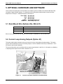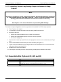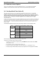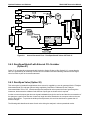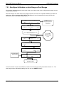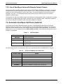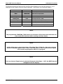
1
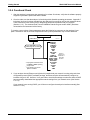
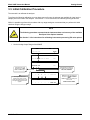
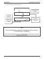
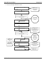
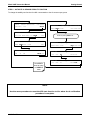
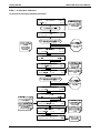
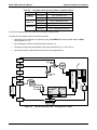
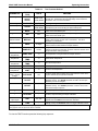
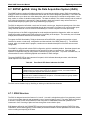
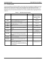
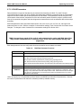
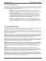
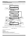
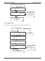
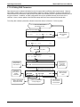
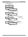
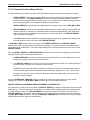
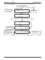
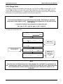
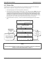
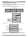
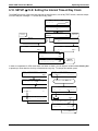
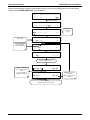
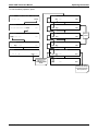
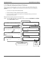
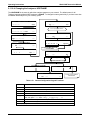
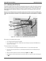
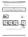
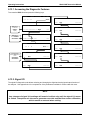
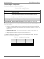
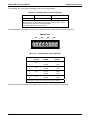
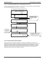
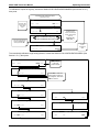
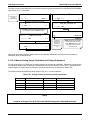
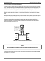
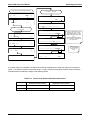
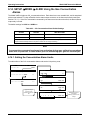
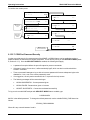
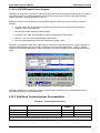
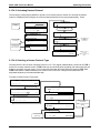
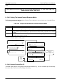
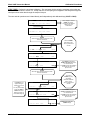
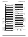
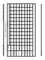
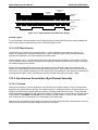
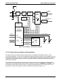
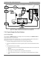
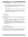
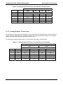
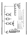
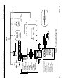
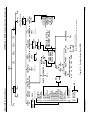
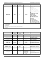
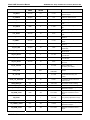
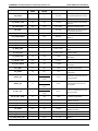
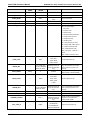
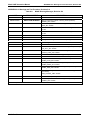
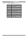
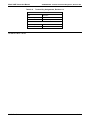
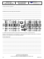
Model 360E Instruction Manual Operating Instructions FROM ANALOG I/O CONFIGURATION MENU DIAG PREV The instrument attempt to automatically calibrate the channel … then beep. ANALOG I / O CONFIGURATION NEXT ENTR DIAG AIO EXIT DIAG AIO CONC_OUT_2 D/A/ CAL ERROR EXIT AIN CALIBRATED: NO SET> EDIT EXIT DIAG AIO CONC_OUT_2 CURR-Z: 0 mV U100 UP10 UP DOWN DN10 D100 ENTR EXIT Press SET> to select the analog output channel to be configured:. DIAG AIO DIAG AIO U100 UP10 UP DOWN DN10 D100 ENTR EXIT CONC_OUT_2:CURR, NO CAL < SET SET> EXIT EDIT DIAG AIO DIAG AIO CONC_OUT_2 RANGE: CURR <SET SET> CONC_OUT_2 SPAN: 10000 mV Increase or decrease the current output by 100, 10 or 1 counts. The resulting change in output voltage is displayed in the upper line. Continue adjustments until the correct current is measured with the current meter. U100 UP10 UP DOWN DN10 D100 ENTR EXIT EDIT EXIT DIAG AIO DIAG AIO CONC_OUT_2 CALIBRATED: NO < SET CONC_OUT_2 ZERO: 27 mV CONC_OUT_2 ZERO: 9731 mV U100 UP10 UP DOWN DN10 D100 ENTR EXIT EXIT ignores the new setting, ENTR accepts the new setting. EXIT CAL DIAG AIO DIAG AIO AUTO CALIBRATING CONC_OUT_2 < SET CONC_OUT_2 CALIBRATED: YES CAL EXIT If a current meter is not available, an alternative method for calibrating the current loop outputs is to connect a 250 1% resistor across the current loop output. Using a voltmeter connected across the resistor, follow the procedure above but adjust the output to the following values: Table 6-21: Current Loop Output Calibration with Resistor 05232 Rev B3 Full scale Voltage for 2-20 mA (measured across resistor) Voltage for 4-20 mA (measured across resistor) 0% 0.5 V 1.0 V 100% 5.0 V 5.0 V 115