1
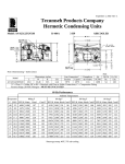
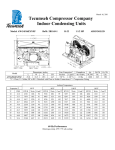
March 16, 2011 Tecumseh Compressor Company Indoor Condensing Units Model: AVA9525ZXNXF BoM: 2B3178-1 R-404A 3 HP AIRCOOLED Dimensions, inches Line Connection* Pumpdown Air L W H CH Suction Liquid SCFM 90 F 90% 25.0 33.6 19.5 16.0 7/8” S 3/8” S 18.14 lbs 1550 AVA9525ZXNXF * F = Flare, S = Solder, RF or RS = Rotolock with Flare or Solder Connections, C = Compression Fitting Model Oil Ch Oz. 38.5 Gr. Wt. Lbs. 220 Ambient Temperatures Evaporator T 80F 90F 100F 110F °F PSIG BTUH Watts Cond T BTUH Watts Cond T BTUH Watts Cond T BTUH Watts Cond T -10 23.2 14094 2618 94 12228 2620 103 10073 2554 112 8121 2404 121 -5 28.1 15980 2819 96 13934 2828 105 11737 2786 114 9690 2674 122 0 32.8 18008 3025 98 15777 3042 107 13509 3024 116 11337 2945 124 5 37.9 20178 3235 100 17757 3262 109 15391 3265 118 13060 3220 126 10 43.3 22490 3449 103 19874 3487 112 17381 3511 120 14861 3496 128 15 49.1 24944 3668 105 22127 3718 114 19480 3762 122 16740 3775 131 20 55.5 27540 3891 108 24517 3954 116 21687 4017 125 18695 4057 133 25 62.2 30277 4118 110 27043 4195 119 24004 4277 127 20728 4341 135 30 69.5 33157 4350 113 29707 4442 121 26430 4541 129 22839 4627 138 35 77.2 36178 4586 116 32507 4695 124 28964 4809 132 25027 4915 140 40 85.5 39341 4826 119 35443 4953 126 31607 5082 134 27292 5206 143 45 94.3 42646 5071 122 38517 5217 129 34359 5359 137 29635 5500 145 60 Hz Performance Return gas temp. 40F Evaporator Temp. 20F or less, 5F sub-cooling Return gas temp. 65F for Evaporator Temp. > 20F, 5F sub-cooling March 16, 2011 Specifications/ Parts: Model Unit Bill of Material Nominal Volts-Hz-Ph Refrigeration Range Design Pressure Low Design Pressure High Voltage Range Min. Circuit Ampacity Max. Fuse Size (amps) Compressor Model Comp. Bill of Material Compressor RLA/LRA Overload Relay Run Capacitor Run Capacitor Rating Start Capacitor Start Capacitor Rating Contactor Unit Drawing Wiring Diagram AVA9525ZXNXF 2B3178-1 208-230-60-1 -10° to 45°F 181 450 187 to 254 29.9 50 AVA9522ZXN AV203ET-001-A2 22.6 / 108.0 INTERNAL 820ARR3J56 85PR440E65 45MFD 440V(M)VDE 85PS330D17 145-175 MFD 330V VDE 91014 DGU1920-37 91263-02 Fan Motor Fan Motor RLA Fan Blade Fan Guard Fan Shroud High Pressure Switch Low Pressure Control Oil Separator * Condenser Fan Switch Fan Switch Receiver Tank Liquid Valve Liquid Filter * Sight Glass * Suction Valve * Rotolock Valve Gasket Discharge Valve Suction Filter * Accumulator * Crankcase Heater Defrost Timer * Suction Shut Off Valve* Liquid Shut Off Valve* Shrader Valve Body* Valve Core* * = Equipped Units Only Electrical Diagram 810F050C20 (2) 0.7 Each 51568-1 (2) 70831 (2) 70648-2 84095-2 84026-2 704-00002 50858-1 84096-1 84096-2 51082-1 31592 70081 70084 31529-1 30233 56596 70082 TK00042000 90699 N/A 56500-K14 56500-K06 56510 56552