1
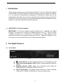
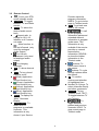
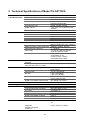
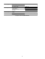
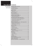
Instruction Manual Standard Definition Digital Terrestrial Receiver Model Number TU-SZT105A ® Trade Mark of the DVB Digital Video Broadcasting Project (1991 to 1996) Declaration of Conformity No.3539, 22 April 2005 Safety Always Comes First This Digital Receiver is manufactured according to Australian safety standards. In order to obtain the best operation results, please read the entire manual, as you will be instructed on how to handle the equipment carefully and safely. Important Safety Tips: CAUTION To reduce the risk of electrical shock, DO NOT REMOVE cover. No User-serviceable parts inside. Refer to Qualified Service Personel. No naked flame sources, such as lit candles, should be placed on the apparatus This symbol is intended to alert the user to the presence of noninsulated dangerous voltage with the product’s enclosure that may be of significant magnitude to constitute the risk of electric shock to persons. This symbol is intended to alert the user to the presence of important operating and maintenance (servicing) instructions in the literature accompanying the appliance. DO’s and DON’Ts DO’s z Avoid exposing the equipment to direct sun rays, excessive heat and moisture, as they will damage the receiver. z Prevent the equipment from overheating. Sufficient ventilation is important. Leave adequate space between the components. z If water or liquid falls or spills into the unit, please turn the receiver off immediately, then have an authorised technician check the unit. DON’Ts z Install the Receiver outdoors. z Install the Receiver in a closet. z Place any objects on top of the ventilation vents. z Place liquid filled containers on top of the unit, which could spill into the receiver. 2 Contents 1 2 3 4 5 6 7 8 9 Introduction...................................................................................................................4 1.1 IMPORTANT: First time Installers .........................................................................4 The Digital Receiver .....................................................................................................4 2.1 Front Panel ............................................................................................................4 2.2 Rear Panel ............................................................................................................5 2.3 Box Contents .........................................................................................................5 The Remote Control .....................................................................................................5 3.1 Preparing the Remote Control ...............................................................................5 3.2 Remote Control .....................................................................................................6 Installing Your Digital Receiver – QUICK CONNECT GUIDE.......................................7 4.1 Installing Your Digital Receiver – QUICK SET UP GUIDE ....................................8 Operating Instructions: Knowing your basic controls ....................................................9 5.1 Switching On Your Digital Receiver.......................................................................9 5.2 Changing or Selecting Channels .........................................................................10 Using the Main Menu..................................................................................................10 6.1 Program Guide ....................................................................................................11 6.2 TV/Radio Channels .............................................................................................13 6.3 Preferences .........................................................................................................13 6.4 Advanced Settings...............................................................................................18 6.5 STB Information...................................................................................................20 Glossary .....................................................................................................................21 Troubleshooting..........................................................................................................22 Technical Specifications .............................................................................................23 3 1 Introduction Thankyou for purchasing you new Panasonic Digital TV receiver. This User’s Manual is the GUIDE to be used to help you install and operate your new digital TV receiver. In it you shall find comprehensive descriptions to familiarise yourself with all the functionalities with which your receiver is equipped. We strongly advise you follow the instructions in this manual. Once you become acquainted with the operations of your receiver you will only need this manual for reference. 1.1 IMPORTANT: First time Installers IMPORTANT: For first time installers, please read Section 4, “Installing Your Digital Receiver”, to learn how to connect your digital receiver to your TV. Once you have completed the setup, go to Section 6.3, “Preferences”, to select various system settings according to your personal preference, and 6.4, “Advanced Settings”, to set your region for correct current time and to conduct channel search. 2 The Digital Receiver 2.1 Front Panel z z z z Power Button: Turns the Digital Receiver On / Off (Standby mode). Front Panel Arrow Buttons: S/T buttons to select channels within the menus. Stand-By Indicator (LED): Lights red in Stand-By mode. When the Digital Receiver is working the LED turns green. Front Panel display: The display shows current time when in standby mode and TV channel number when in normal viewing mode 4 2.2 Rear Panel • • • • DC Power Mains: (100 - 250VAC~; 50/60 Hz), Power 15W Max. RF IN: Used for connection of the cable from your outdoor terrestrial TV antenna. RF OUT: Used for connection to your TV RF antenna Input or your VCR RF Input. AUDIO: (connectors L and R) is used for analogue stereo audio output connection to analogue TV or VCR. Digital Audio: SPDIF output for connection to your TV or other A / V receiver (eg home theatre system). Component Video / RGB / Video (SCART): Used for connection to your TV set. Serial Port (RS232): Used for system maintenance only. • • • 2.3 Box Contents The box that carries your Digital TV Receiver should also contain the following items: z z z z z Remote Control Two Batteries (AAA Size) SCART to RCA Connector Cable RF Cable User’s Manual and Warranty Card 3 The Remote Control 3.1 Preparing the Remote Control z z z z Remove the cover of the battery compartment (on the back of the remote control) Insert 2 AAA (1.5V) batteries. While inserting, observe the + and – markings indicated inside the battery compartment. Replace the cover Test the remote control by pressing the key and toggle the unit from standby to normal viewing ON mode and observe the light on the front panel toggles between red (standby mode) to green (normal viewing ON mode). 5 3.2 z z z z z z z z z z z z z z z Remote Control : To turn your STB on/off (standby mode) TV/RADIO: To toggle between TV and Radio service AUDIO: To select the desired audio sound track : Aspect ratio, to change to 16:9, 4:3 letterbox or 4:3 centrecut mode : Mute function, to turn on/off sound (only used for analogue Audio Output) For Volume adjustment (only used for analogue audio output) For changing channels LIST: To show channel list STTL: To turn closed captions on/off (Red): Application defined function key (Green): Application defined function key (Yellow): Application defined function key (Blue): Application defined function key MENU: To display the “Main” Onscreen Display GUIDE/INDEX: To obtain a list of programs on available channels. This information is only shown if your Service z z z z z z z z 6 Provider transmits program information; INDEX: To go to index page in Teletext mode EXIT: To go back one level in the menus. : To call up the program information plates and extended channel information in program guide menu. This information is only available if the service provider or network transmits the information. REVEAL: to show the hidden information in the Teletext mode. buttons: To select menu items in the menus. buttons: To cycle through options within the menus OK: To confirm choices and selection of highlighted item Number (0~9) keys: To select channels directly and other commands TV/TEXT: To turn Teletext on/off; TEXT: To toggle between TV and Teletext : To toggle between present and previous channels; HOLD: To stop current page in Teletext mode 4 Installing Your Digital Receiver - Quick Connect Guide The Set Top Box and the television use a number of different connectors. The main ones that you need to identify are: POWER RF SCART RCA The POWER connector is used to connect mains power (via the power pack) to the Set Top Box. RF connectors are used for connecting antenna leads. The SCART connector and RCA connectors are used for video and audio connections. Start: To TV 1 Connect the power pack to the Set Top Box. Use the connector marked POWER. 2 Connect the Set Top Box to a good quality outside / roof antenna. Use the connector marked RF IN. 3 Use the included SCART to RCA connection lead to connect to your television. 4 Connect the red audio lead to the red audio connector on the television. Connect the white audio lead to the white audio connector on the television. Remember that you must connect the video to the same AV Input as the audio. If TV has COMPONENT VIDEO If your television has CVBS OUT (Yellow) Component inputs (also Not used called YPBPR, DVD, YUV or YCBCR) use them as they will give the best picture. Connect the AUDIO OUT R (Red) AUDIO OUT L (White) Television AV Input R (Red) AUDIO IN L (White) PY OUT (Green) Y IN (Green) PB OUT(Blue) PR OUT(Red) PB IN (Blue) PR IN (Red) red video lead to the red video in connector on the television. Connect the blue to the blue and the green to the green. Do not connect the yellow lead. If TV has Composite ( CVBS) VIDEO AUDIO OUT R (Red) Television AV Input If your television does not have Component inputs then connect the yellow lead to the yellow CVBS OUT (Yellow) connector on the television but Y OUT (Green) VIDEO IN P (Blue) do not connect the green, blue or (Yellow) and P (Red) Not used red video leads. Turn the TV and the Set Top Box ON. Using the TV remote control, select the AV Input that the Set Top Box has been connected too. AUDIO OUT L (White) R (Red) AUDIO IN L (White) B R 7 4.1 Installing Your Digital Receiver – Quick Set Up Guide Installation SCART Mode The first time the digital receiver is installed, or after Default Condition is restored (section 6.4), you will be asked to select the video connection format. Select the video format that is the same as the AV lead connection you have made to the TV display (refer Quick Connect Guide section 4). Please select SCART mode Component Composite RGB Select Region The first time the digital receiver is installed, or after Default Condition is restored (section 6.4), you will be asked to select the region you live in so that the digital receiver will display the correct local time. The regions are New South Wales, Victoria, Queensland, South Australia, Western Australia, Tasmania, Northern Territory and Australian Capital Territory and are selected by the up/down cursor keys. Please select your state / region New South Wales Victoria Queensland South Australia Western Australia Tasmania Northern Territory Australian Capital Territory Select Aspect Ratio The first time the digital receiver is installed, or after Default Condition is restored (section 6.4), you will be asked to select your preferred aspect setting. This is a choice of the Wide (16:9), Normal / Centre Cut (4:3) or Normal / Letter Box (4:3). Select the aspect that is correct for your TV display. This can be changed at a later date. Please select your preferred display aspect ratio Wide (16:9) Centre Cut Letterbox Preferred Audio Type The audio can be received in two format types, Dolby Digital and MPEG. The broadcasters sometimes use both types, please select which format that you prefer to listen to. This format will be select when the broadcaster transmits both types. This can be changed at a later date. Autotune The first time the digital receiver is installed, or after Default Condition is restored ( Section 6.4), the digital receiver will Automatically scan for available digital services. This may take Up to 5 minutes. After tuning finishes press OK. 8 Please select the audio type you prefer MPEG1 Dolby Digital 5 Operating Instructions: Knowing your basic controls To become acquainted with the operations and functions of your receiver, you should learn how to use the control buttons on the Front Panel and the Remote Control. The following section is an introduction to the features that will be most commonly used. 5.1 Switching On Your Digital Receiver Ensure the power lead of the power adaptor is plugged into a 240V AC socket. Switch on the 240V AC socket at the wall. Turn on your digital receiver by pressing either the .button on the remote control or the button on the front panel. When the digital receiver is in normal viewing ON mode, the LED turns green. When the receiver is not being used, place the receiver in the "STANDBY" mode, by pressing either one of the / buttons again. When the LED turns red, it indicates the digital receiver is in “STANDBY” mode. Information Plate The Information Plate (I-Plate) shows information about the program that you are currently watching. The information plate appears briefly whenever you switch to a new channel or when there’s a problem with TV signal reception. To show the information plate, press the button. Press EXIT to remove the I-Plate from the screen. Program Guide The Program Guide is a user-friendly feature, which enables you to select and book programs. To enter into the Program Guide, press GUIDE/INDEX. In the Program Guide on-screen display, the program schedule is listed in chronological order. Press EXIT to remove program guide from the screen. Section 6.1 of your User Manual will instruct you to use the Program Guide efficiently. 9 5.2 Changing or Selecting Channels There are several methods to change or select a channel. You can either use the front panel on the receiver or the remote control buttons. The following methods are available for you to choose from: z z z z Press on the remote control (channel changes according to favourite channel settings). Directly enter a channel number by using the number keys on the remote control. Use arrow up/down to change channel. Unlike control channel movement is not aligned with favourite channels setting. Use to toggle between current channel and previously watched channel 6 Using the Main Menu Your receiver comes with a directory of features on the Main On Screen Display (OSD). The Main OSD is your gateway to customising many of the features offered by your receiver. To access the Main OSD, press the MENU button. The Main OSD feature comprises the following categories of services: Program Guide provides access to: (1) Programs Schedule (2) Programs Categorisation/Type (3) Booked Programs TV/Radio Channels allows you to program: (1) Favourite Channels (2) Channel Locking (3) Channel Deletion Preferences allows you to access: (1) Screen Format (2) SCART Mode (3) MPEG Audio Level (4) Audio Mode Priority (5) Digital Audio (6) Stereo Surround (7) Audio Balance (8) Audio Delay (9) Teletext Contrast Advanced Settings gives access to: (1) Parental Guidance (2) Change Password (Default value is 0000) (3) Channel Installation 10 (4) Restore Default Settings (5) Region Select STB Information: (1) To display the Software Version number and Serial ID of your receiver. 6.1 Program Guide Program Schedule By choosing the Program Guide banner on the Main OSD, the Electronic Program Guide (EPG) appears. The EPG is, in classic terms, a TV Guide, except it is presented on your TV screen. The EPG allows you to peek in advance, depending on TV services provided by the broadcaster, next program, a few days or up to one week of TV programs and program information. By using the arrow keys on either your receiver or the remote control, you can roam the EPG to access various channels and programs. In the list, highlight the desired program by pressing the arrow buttons. Once you have selection of your choice (the highlighted block will appear in a different colour), press to view the detailed description of the program. If the broadcaster has not transmitted detailed description for the program, the text “No description available” will appear. If you wish to see what programs are being broadcast on other channels, use the button to access the list of all programs shown for the current and next days viewing (subject to availability). If you wish to book a future program, highlight any program (beyond the current time frame) by using the arrow buttons, and press OK to confirm your selection. The “Booking” window will appear allowing you to book the program. Press OK to confirm the booking, or EXIT to exit the Booking window. For more information on the Booking feature, see “Booked Programs” on page 12. Note that if you highlight a program currently being broadcasted on another channel and press OK, the program is not booked. Instead, the receiver switches to that channel directly. 11 Coloured “Hot Keys” On the Program Guide window, you will notice two coloured hot keys. They provide instant access to various services. Category Selection This special feature enables you to identify your preferred programs by program Category or type. You can gain access to this feature by pressing the .button (yellow). Use the arrow buttons to highlight the categories, and press OK to select or unselect any of the categories. By default, the item “All Categories” is highlighted. You have to de-select that item before selecting specific program type(s). As you select some categories and go back to program guide menu, only programs of the selected categories will be visible. Booked Programs To review what programs are currently booked, press (blue) to call up the Booked Programs OSD. To cancel or re-engage the booking, press OK. If the symbol (the alarm clock) disappears, then the timer is disengaged. The program information will remain in case you wish to rebook the program. The cancelled program will not be displayed the next time this window reappears. 12 6.2 TV/Radio Channels You may highlight any channel in the list by pressing up/down keys, then press OK to view that channel directly. This feature allows you to personalise your list of favourite channels, TV or Radio. Highlight a channel by using the S/T buttons, then press the .“hot key” (red) to select or unselect. When a channel is selected a symbol will appear in the bar to indicate the favourite status. When you are changing channels using the key, the receiver jumps to the next/previous favourite channel, and skips other channels. If you wish to lock or unlock any channel, simply press the button (green) to do so. When a channel is locked a symbol will appear to indicate the locked status. Whenever you wish to watch the locked channel you will be asked to enter the password. If you wish to delete any channel, press the button (yellow) and an “X” sign will be shown on that channel. You may un-delete that channel by pressing the same key again. If one or more channels are deleted, you will be asked to confirm the removal of those channels upon leaving the TV/Radio channels menu. Once you confirm their removal, you cannot undelete them. The only way to recover those deleted channel is to perform an “Install”. Please use this feature very carefully. To toggle between the TV ( TV ) and Radio ( 6.3 ) lists, press the TV/RADIO button. Preferences From here, you may adjust various settings according to your personal preference, such as screen format, SCART mode, audio delay time, digital audio and others. Note that some settings in this segment are related to the A/V equipment to which the digital receiver is connected. Instructions on how to set each item are listed on pages 14, 15 & 16. 13 Screen Format This setting affects the video format at the TV output. (4:3 relates to normal screen format, 16:9 relates to widescreen format) If your display is 4:3 format and the transmission of a program happens to be 16:9, the Normal/Letterbox mode will give you a complete picture, but black areas will appear at the top and bottom. Letterbox Alternatively you can choose the Normal / Centre Cut mode to play the program in a full-screen format, however information on the left and right sides may be cut off. If your display is 16:9 format, then set the mode at Wide. If a program happens to be in 4:3, black areas will appear at the left and right of the screen in order to present the picture in a correct viewing aspect ratio. Center Cut SCART Mode From here you may adjust SCART mode to Component output or Composite output or RGB output. You must choose the correct mode to match the video input Connection of the TV that you did in the Quick Connect Guide. 16:9 W ide MPEG Audio Level From here you may adjust MPEG audio level from –12 db to 0 db. This adjustment only applies when MPEG audio is being received. The system detects MPEG audio automatically. Audio Mode Priority z The Audio mode allows you to adjust the audio setting. You may choose Dolby Digital (Dolby D) or MPEG1. Use W/X to select your choice. This setting determines your initial choice of soundtrack based on the audio mode, and you may select any soundtrack channel by channel, regardless of the audio mode setting made in this menu. 14 If the default Audio Mode is Dolby D, and the input signal contains only MPEG1, the default Mode will change to MPEG1 automatically. If the Audio Mode is set to Dolby D, the digital receiver will automatically select a Dolby D soundtrack when it is available. When using the SPDIF digital output, we recommend this selection if you are connecting your receiver to a TV or A/V receiver that can decode Dolby Digital. You can switch between Dolby D and MPEG audio by pressing the Red key on the remote control. Digital Audio For each Audio Mode, you can have different Digital Audio Selection Options. (Refer to Table 2, Digital Audio Selection Table) Table 2: Digital Audio Selection Table Default Audio Mode Dolby Digital MPEG-1 Digital Audio Selection Options 1. Bitstream 2. PCM (stereo) 3. Off 1. PCM (stereo) 2. Off ◆ Bitstream: Select this if your TV or A/V receiver has a digital audio input and can decode Dolby Digital ◆ PCM (stereo): Select this if your TV or A/V receiver has a digital audio input but can not decode Dolby Digital ◆ Off: There will be no digital audio output from SPDIF interface. Stereo Surround You can toggle Stereo Surround ON or OFF by pressing W/X On: There will be surround sound information (Lt / Rt) to be included in Audio L&R output. You can enable the stereo surround option, if your TV or external A/V receiver has the capability to decode surround sound. 15 Off: There will be only stereo audio information (L / R) to be included in Audio L&R output. Audio Balance You can adjust the value from L+7 to R+7. The selection “0” means balanced (equal level) output on the two front speakers. Audio Delay Different displays may have different delay in displaying pictures, which may cause a slight problem with lip sync. This feature allows you to use W/X to select your choice according to your actual video display equipment, in order to compensate for this delay. The delay time depends on which choice appears to provide best performance of lip sync on your display device. Teletext contrast The OSD contrast of teletext pages can be adjusted by selecting different options. Teletext Operation Teletext is only available on certain broadcast channels. The time taken to display the pages and sub-pages is set by the teletext transmitter. Teletext is also used for Closed Captioning of television programmes for the hearing impaired. Closed captions can be found on Teletext Page 801. The picture remains on the screen while you type in 801. Some broadcast stations will have a message on the screen to tell you that closed captions are not available for this programme. Some broadcast stations give you no indication at all. 16 TOP (Table Of Pages) MODE In TOPTEXT mode, the red button moves to the previous page number and the green button moves to the next page number. The yellow and blue buttons correspond to different subjects. Pushing the coloured button can access these subjects. This is the current preferred method of operation in Australia. Red /Green / Yellow / Blue buttons In TOP TEXT mode these correspond to the differently coloured subjects. TV / Teletext mode Press the TEXT button. The screen will display the Teletext page. Press again when you wish to return to TV mode. Note: If you press the TEXT button while viewing a station that is not transmitting teletext, there may not be any indication on the screen. Press the TEXT button to return to normal viewing. STTL Displays subtitles (if available). This is the same as turning the teletext ON and selecting page 801. Page Selection Pages can be selected in two ways: a. Press the Up / Down buttons to increase or decrease the page number by one. b. By entering the page number, using 0 - 9 on the remote control. Hold Used to hold the Teletext page when viewing multi-page information. Press again to return to automatic page update. Index When In TOP TEXT operation press INDEX to return to the main index page. Depending on the way information is transmitted, this may have to be pressed more than once to return to the main index page. Reveal To reveal hidden words e.g. quiz page answers. Press again to hide. 17 Sub Coded Page Access When Teletext information exceeds more than one page, it may take some time for the automatic changing of the sub pages to reach the sub page you require. As each sub page is found its number is displayed at the bottom of the page so that you may select it by pressing left or right cursor key. As more sub pages are picked up, the display at the bottom of the page changes, so that you are always offered the most recently transmitted selection of sub pages. While selecting dynamic mode , sub page will be changed dynamically and it will depend on which page now is available. And you can fix on specific sub page by pressing HOLD key, while in dynamic mode. You can also access to specific sub page by pressing left / right cursor key to select the sub page number. 6.4 Advanced Settings (Default password: 0000) In addition to the settings in “Preferences”, section 6.3, the Advanced Settings are used to program your digital receiver. Again, some of the settings, especially “Channel Installation”, may require assistance from your Service Provider. Your digital receiver will ask you to key in a password, and the default password is 0000. Parental Guidance Using W/X you may select to block programs with a certain rating or above: None, Block G, Block PG, Block M, Block MA, Block AV, Block R, and Block All. Your digital receiver will automatically block programs that are unsuitable to children under the age limit you have set. For example, if you choose “Block PG” and a received program has rating equal to or above PG, the digital receiver will ask the viewer to enter the password before viewing that program. 18 However, not all transmissions carry ratings information to activate this function. Change password From here you can change the password. Once the new password is set DO NOT FORGET IT! If you change the password, we strongly suggest that you write down the new password in the □□□□ area. Without the password, you cannot access any functions that require you to provide the correct password! Channel Installation When the receiver is initially set up, conduct a channel search by selecting the “Auto scan channels” function. Auto Scan channels Auto Scan channels provides the easiest way to conduct a channel search. It does not require you to enter any other information. This function is strongly recommended for regular users. However, the user should be aware that all existing channels will be removed as soon as you confirm start of auto scan. In the Auto Scan channels OSD, all channels found will be listed. The channel search may take a few minutes. If you abort an auto scan during the scan process, some channels may not be available to you. Manual Channel Search In the “Manual channel search” window you can set the specific channel to search. Press the left or right button then OK to select the physical channel you wish to search. Note: the number displayed is not the TV channel number Restore Default Settings If you wish to reset all previous settings, you can use this feature to do so. Once you decide to restore shipping settings, all previous settings will be lost. Please be very careful before you confirm this action. 19 Select Region Using W/X you may select your local region: NSW, Victoria, Queensland, South Australia, Western Australia, Tasmania, Northern Territory, and Australian Capital Territory. This setting will allow the digital receiver to display the current time in the I-Plate or when the receiver is in Stand-By mode. 6.5 STB Information From here, you can get general information about the Receiver ID, software and hardware version on which it is operating. 20 7 Glossary Information Plate: A small window with simple navigation tools to display information about individual channels. Menu: An on screen display offering a list of commands to select from. Normal viewing: The state of your receiver when no menus or windows are displayed on the screen, and a valid channel is tuned. Parental Guidance: A feature enabling parents to “lock” programs that they consider unsuitable for children’s viewing. A “locked” program can only be “unlocked” with the Password. Password: A personal 4-digit numbers for controlling specific features of the digital receiver, including access to locked channels. Also known as the PIN Number. Electronic Program Guide (EPG): The instantaneous and continuously updated electronic program guide for quick and easy reference or program selection. Network: The Network that provides one or more services to the viewers. OSD: On screen display Set-Top Box (STB): A device that is capable of decoding and tuning digital signals and converting these signals into a format that is understood by your TV set. Standby mode: A condition in which your receiver allows retrieval of updated information from input signals. 21 8 Troubleshooting Problem Possible causes What to do The display on the panel does not light up / is not lit Power adaptor is not connected Check that the external power adaptor is plugged into the power source and the back of the Receiver. No sound or picture The SCART to RCA connector Cable is not properly connected Check the cable connections and other equipment connected to your receiver Wrong selection of output mode Try another output configuration Battery exhausted Change the batteries Fluorescent light interfering with the remote control Switch off the light Remote control is incorrectly aimed Aim the remote control at the receiver Unable to tune TV antenna not plugged in or Digital TV not available in the area Check the antenna cable connections or check if you require to upgrade your antenna to receive digital TV signals in your area. I get “blocky” small squares forming on the screen or sometimes the picture freezes Could be caused by low TV signal strength or poor quality reception To check the signal level use the information plate as described on page 9. If the signal strength % is black in colour you will have adequate signal strength. Any other colour you may need to have your antenna and antenna cabling checked Why does the show guide (EPG) show some digital TV stations but I can not receive them Some of the digital TV stations are transmitted in high definition (HD). This set top receives standard definition (SD) TV stations only and will not display HD stations If you want to pick up HD TV stations you will require a HD set top box Why does the television set top box not have all channels tuned It is possible that the signal level for a TV channel might have been low for some reason during the tuning process Repeat the setup procedure for tuning in TV stations Why does the picture on the TV look green It is possible that the red video RCA lead and the red audio RCA lead on the back of the TV may be connected incorrectly Change around the two red RCA leads on the back of the TV The remote control is not working 22 9 Technical Specifications of Model TU-SZT105A Terrestrial Tuner/Demodulator Input frequency Standard Channel Bandwidth COFDM System VHF, UHF Band DVB-T (ETS 300 744) 7/7 MHz, Australian Channel 2K, 8K carrier Hierarchical supported QPSK, 16QAM, 64QAM 1/32, 1/16, 1/8, 1/4 active symbol duration 1/2, 2/3, 3/4, 5/6, 7/8 STi5518M / 81MHz DVB Demultiplexer 2 MB 8 MB Demodulation type Guard Interval System Video decoder FEC CPU / Clock Transport Flash memory Shared memory Bitstream accepted for Video MPEG-2 profiles / levels Supported Video data rate supported Aspect ratio Video output Caption / Teletext Audio decoder Decoding and display of Closed Captions Decoding and display of Teletext (ETS 300 706, Level 1.5, TOP) Audio Sampling rate Bit rates Audio output Serial Port Software Upgrade Rear panel interface Front panel Digital Audio SPDIF Output format RS-232 Support Over Air Download RF input connector Loop through output connector A/V output CVBS video output Stereo (left & right) Audio output Digital Audio SPDIF (Coaxial) RS-232 Power Jack 1 dual colour LED indicator 3 keypads 4-digital 7-Segment IR Sensor MPEG-1 Video (ISO / IEC 11172-2) MPEG-2 Video (ISO / IEC 13818-2) MP@ML, SP@ML, MP@LL 1 ~ 15 Mbps 4:3 and 16:9 with Pan & Scan, Support Letter Box mode PAL (720x576i) One SCART for TV (CVBS, R-G-B, Y-Pb-Pr) Composite video CVBS Activated by specific hot-key Activated by specific hot-key ISO11172-3 layer I and layer II Dolby Digital 32, 44.1 and 48KHz Layer I 32-448KHz Layer II 32-384KHz Stereo Audio AL / AR and down mixing surround Lt/Rt IEC-60958 / IEC-61937 Up to 115200 bps ETSI Standard IEC type, Female, 75 ohm IEC type, Male, 75 ohm TV SCART x1 RCA x1 RCA x2 RCA x1 DB-9, Female RED for Standby and GREEN for On Power, CH Up, CH Down 23 Power Supply Accessory EMC / Safety General Information External Adaptor Main AC input 100 - 250 VAC~, 50/60 Hz DC output to STB 12VDC, 1A Remote Control Batteries User’s Manual SCART to RCA (6) RF Cable Panasonic RO3 AAA One (CVBS/Y/Pb/Pr/AL/AR) 3C-2V IEC male to female Compliant to AS/NZS 1053 / AS/NZS 60065 Dimensions 268x185x45 mm (L x W x H) Weight (Net) TBD Copyright © 2005 All Rights Reserved. 24