1
2 – Parts of the DS-M7.1
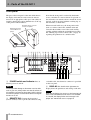
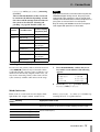
8 MASTER RECORDER I/O There are
three sets of connectors for connecting the master
recorder: TDIF-1 (combined input and output), ADAT
(separate input and output “lightpipe” connectors)
and AES/EBU (combined input and output).
9 REMOTE IN 1 Use this as an alternative to
the front panel REMOTE IN 2 connector when using
the front panel as a remote control. See “Making up a
remote control cable” on page 38 for details.
A RS-232C Reserved for future software
upgrades.
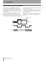
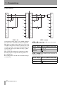
B MUTE/DIMMER This 3.5 mm stereo mini
jack socket is used to connect switches which can be
used for remote MUTE ALL/DIM operation. Con-
12 TASCAM DS-M7.1
nect tip to sleeve for the mute control, and ring to
sleeve for the dimmer. Switches used in this way are
active when closed, and should be non-latching. See
“Dimmer and mute control connections” on page 18.
C ~ IN (power input) Use the supplied power
cord to connect the DS-M7.1 to the power supply.
Ensure that the power supply is the correct voltage
(as marked on the rear panel of the unit). If you are in
any doubt, consult a qualified electrician.
NOTE
Always connect and disconnect the power with the
power switch on the front panel of the DS-M7.1 turned
OFF. If the power cord is connected or disconnected
with this switch on, there is a risk of damage to the
unit.