1
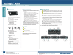
Installation of X-Port 10 with Director
This document explains how to connect the X-Port 10 to the Director system. This feature allows easy
connections for an external portable computer and automatic switching between the internal and external
computer with the Director system.
Supplied Components:
•
•
•
•
•
•
•
•
•
1 Connector Box
1 RS232 Blanking Plate
1 Pair of export 10 Mounting Bracket (Left and Right)
2 T201-0036 Cables, 1 T201-0072 Cable, 1 T237-0072 Cable, 2 T112-0036 Cables, 1 T3230036 Cable, 1 T325-0072 Cable, 1 T324-0036 Cable, 1 T308-0036 Cable, 1 HD15D-Sub to
BNC cable
1 TANDBERG Director label
4 #10-32 G-style panel nut retainer and 4 #10-32 x ¾” Black rack screw with washer
10 Black adhesive cable tie mounting base14 cable ties 4” long
2 #4-40 x 3/16” screws
1 instruction sheet
RS232 Blanking Plate Installation:
•
Install the blanking plate over the Computer 2
Serial connector located on the rear of the
Smart 3000i projector unit using the 2 supplied
#4-40 x 1/8” screws.
Connector Box Installation:
•
•
•
Install the connector box on the rear of the
Smart 3000i as shown.
Use the existing screws on the 3000i projector
to fasten the connector box.
Route the cables through the opening and
connect them as per labels. (See System
Connections)
1
D5018501
X-Port 10 Installation:
•
•
•
Remove the existing brackets from the X-Port 10
unit and replace them with the supplied left and
right brackets. Use the same screws for mounting
the new brackets.
Insert the four 10-32 panel nut retainers on the rear
left rack mount rail of the 3000i projector. Insert 1
panel nut retainer at the lowest hole, skip 1 hole
insert another, skip 6 holes insert another, skip 1
hole insert another.
Install the X-Port 10 unit to the exterior of the rack
within the 3000i projector. Use the supplied 10-32
x ¾” screws to fasten the X-Port 10.
DC Power Connection to X-Port 10:
•
•
•
•
•
Locate the DC power cable supplied with the Xport 10.
Remove the Room Control Module (RCM) or the
blank plate and the X-Port 20 panel.
Connect one end of the DC power cable to the XPort 20 through the Room Control Module (RCM)
hole.
Bring the cable down from the side and connect the
other end of the DC power cable to the X-Port 10
connector labeled as Power Supply.
Fasten the cable using the supplied tie wraps to
prevent disconnection.
DC Power Connector
X-Port 20
RCM or Blank Plate
Logo Installation:
Apply the provided TANDBERG Director label to the top right hand corner of the Smart 3000i projector.
The label will help differentiate the type of system you have if and when technical help is required.
2
D5018501
System Connections:
Connect the cables as shown in the diagram below and by matching the cable labeled ends to the
corresponding equipment.
DIRECTOR APPLICATIONS MODULE
PC VGA IN
AUX CTRL 1
AUX CTRL 3
DISPLAY VGA OUT
AUX CTRL 2
PROGRAM
TOUCHPANEL
TOUCHSCREEN
MOUSE
CRESNET
LAN
DIAGNOSTICS
SMART X-Port 10
T112-0036
T201-0036
T308-0036
PROJECTOR
VIDEO
PEN
TRAY
DATA
T112-0036
COMPUTER 1
VIDEO
COMPUTER 1
SERIAL
T201-0036
COMPUTER 1
AUDIO
INTERNAL
COMPUTER 1
T324-0036
SPEAKER
SEE NOTE 1
NOTES:
1 - CABLE PART OF 3000i
(LABELLED AS RGB 2 IN)
COMPUTER 2
VIDEO
2 - CABLE SUPPLIED WITH X-PORT 10
CONNECTS TO X-PORT 20 INTERNAL TO 3000i
COMPUTER 2
SERIAL
T237-0072
POWER SUPPLY
COMPUTER 2
AUDIO
T325-0072
SEE NOTE 2
RGB OUT
SERIAL
AUD OUT
REAR INTERFACE PANEL ON 3000i
3
RGB OUT
SERIAL
AUD OUT
EXTERNAL
COMPUTER 2
CABLE LOOM WITH 3000i
D5018501