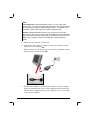
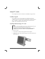
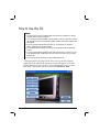
1
MIL-BOOK 20 SERIES NOTEBOOK
OPERATOR’ S MANUAL
22355 TAG Way, Dulles, VA 20166
Tel: (703) 406.3000 Fax: (703) 607.3853
TRADEMARKS
All brand and product names are trademarks or registered trademarks of their
respective companies.
NOTE
Information in this manual is subject to change without notice.
i
Regulatory Information
This appendix provides regulatory statements and safety notices on your
computer.
NOTE: Marking labels located on the exterior of your computer indicate the regulations
that your model complies with. Please check the marking labels and refer to the
corresponding statements in this appendix. Some notices apply to specific models only.
ii
On the Use of the System
Class B Regulations
USA
Federal Communications Commission Radio Frequency Interference
Statement
NOTE:
This equipment has been tested and found to comply with the limits for a
Class B digital device pursuant to Part 15 of the FCC Rules. These limits
are designed to provide reasonable protection against harmful interference
in a residential installation. This equipment generates, uses, and can radiate
radio frequency energy and, if not installed and used in accordance with the
instructions, may cause harmful interference to radio communications.
However, there is no guarantee that interference will not occur in a
particular installation. If this equipment does cause harmful interference to
radio or television reception, which can be determined by turning the
equipment off and on, the user is encouraged to try to correct the
interference by one or more of the following measures:
Reorient or relocate the receiving antenna.
Increase the separation between the equipment and receiver.
Connect the equipment into an outlet on a circuit different from that to
which the receiver is connected.
Consult the dealer or an experienced radio/TV technician for help.
Any changes or modifications not expressly approved by the manufacturer
could void the user’s authority to operate the equipment.
Please note:
The use of a non-shielded interface cable with this equipment is
prohibited.
iii
Canada
Canadian Department of Communications
Radio Interference Regulations Class B Compliance Notice
This Class B digital apparatus meets all requirements of the Canada
Interference-Causing equipment regulations.
Cet appareil numérique de Classe B respecte toutes les exigences du
Règlement Canadien sur le matériel brouileur.
This digital apparatus does not exceed the Class B limits for radio noise
emissions from digital apparatus set out in the Radio Interference
Regulations of the Canadian Department of Communications.
Le présent appareil numérique n’émet pas de bruits radioélectriques
dépassant les limites applicables aux appareils numériques de la classe B
prescrites dans le Règlement sur le brouillage radioélectrique édicté par le
ministère des Communications du Canada.
Safety Notices
About the Battery
Caution Texts Concerning Lithium Batteries
DANISH
ADVARSEL! Lithiumbatteri – Eksplosionsfare ved fejlagtig håndtering. Udskiftning må
kun ske med batteri af samme fabrikat og type. Levér det brugte batteri tilbage til
leverandøren.
NORWEGIAN
ADVARSEL: Eksplosjonsfare ved feilaktig skifte av batteri. Benytt samme batteritype
eller en tilsvarende type anbefalt av apparatfabrikanten. Brukte batterier kasseres i
henhold til fabrikantens instruksjoner.
SWEDISH
VARNING: Explosionsfara vid felaktigt batteribyte. Använd samma batterityp eller en
ekvivalent typ som rekommenderas av apparattillverkaren. Kassera använt batteri enligt
fabrikantens instruktion.
FINNISH
VAROITUS: Paristo voi räjähtää, jos se on virheellisesti asennettu. Vaihda paristo
ainoastaan valmistajan suosittelemaan tyyppiin. Hävitä käytetty paristo valmistajan
ohjeiden mukaisesti.
iv
ENGLISH
CAUTION: Danger of explosion if battery is incorrectly replaced. Replace only with the
same or equivalent type recommended by the equipment manufacturer. Discard used
batteries according to manufacturer's instructions.
DEUTSCH
VORSICHT: Explosionsgefahr bei unsachgemäßem Austausch der Batterie. Ersatz nur
durch denselben oder einen vom Hersteller empfohlenen gleich-wertigen Typ.
Entsorgung gebrauchter Batterien nach Angaben des Herstellers.
FRENCH
ATTENTION: II y a danger d’explosion s’il y a remplacement incorrect de la batterie.
Remplacer uniquement avec une batterie du même type ou d’un type équivalent
recommandé par le constructeur. Mettre au rebut les batteries usagées conformément aux
instructions du fabricant.
Attention (for USA Users)
The product that you have purchased contains a rechargeable battery. The battery is
recyclable. At the end of its useful life, under various state and local laws, it may be illegal
to dispose of this battery into the municipal waste stream. Check with your local solid
waste officials for details in your area for recycling options or proper disposal.
About the AC Adapter
Use only the AC adapter supplied with your computer. Use of another
type of AC adapter will result in malfunction and/or danger.
Do not use the adapter in a high moisture environment. Never touch
the adapter when your hands or feet are wet.
Allow adequate ventilation around the adapter when using it to
operate the device or charge the battery. Do not cover the AC adapter
with paper or other objects that will reduce cooling. Do not use the AC
adapter while it is inside a carrying case.
Connect the adapter to a proper power source. The voltage
requirements are found on the product case and/or packaging.
Do not use the adapter if the cord becomes damaged.
Do not attempt to service the unit. There are no serviceable parts
inside. Replace the unit if it is damaged or exposed to excess moisture.
v
About the Modem
Caution
1. Never install telephone wiring during a lightning storm.
2. Never install telephone jacks in wet locations unless the jack is
specifically designed for wet locations.
3. Never touch non-insulated telephone wires or terminals unless the
telephone line has been disconnected at the network interface.
4. Use caution when installing or modifying telephone lines.
5. Avoid using the telephone function (other than a cordless type) during
an electrical storm. There may be a remote risk of electric shock from
lightning.
6. Do not use the telephone function to report a gas leak in the vicinity of
the leak.
7. Do not use this product near water, for example near a bathtub, wash
bowl, kitchen sink or laundry tub, in a wet basement or near a
swimming pool.
Caution (for USA Users)
To reduce the risk of fire, use only No.26 AWG or larger
telecommunication line cord.
vi
On the Use of RF Device
NOTE: The information in this section applies to models with the wireless LAN module.
USA and Canada Safety Requirements and Notices
IMPORTANT NOTE: To comply with FCC RF exposure compliance
requirements, the antenna used for this transmitter must be installed to
provide a separation distance of at least 20 cm from all persons and must
not be co-located or operating in conjunction with any other antenna or
transmitter.
Radio Frequency Interference Requirements and SAR
The FCC with its action in ET Docket 93-62 has adopted a safety standard
for human exposure to Radio Frequency (RF) electromagnetic energy
emitted by FCC certified equipment. The wireless LAN module meets the
Human Exposure limits found in OET Bulletin 65, 2001, and ANSI/IEEE
C95.1, 1992. Proper operation of this radio according to the instructions
found in this manual will result in exposure substantially below the
FCC’s recommended limits. The following safety precautions should be
observed:
Do not touch or move antenna while the unit is transmitting or
receiving.
Do not hold any component containing the radio such that the antenna
is very close or touching any exposed parts of the body, especially the
face or eyes, while transmitting.
Do not operate the radio or attempt to transmit data unless the antenna
is connected; if not, the radio may be damaged.
Use in specific environments:
The use of wireless devices in hazardous locations is limited by the
constraints posed by the safety directors of such environments.
vii
The use of wireless devices on airplanes is governed by the Federal
Aviation Administration (FAA).
The use of wireless devices in hospitals is restricted to the limits set
forth by each hospital.
Antenna use:
In order to comply with FCC RF exposure limits, low gain integrated
antennas should be located at a minimum distance of 20 cm (8 inches)
or more from the body of all persons.
High-gain, wall-mount, or mast-mount antennas are designed to be
professionally installed and should be located at a minimum distance
of 30 cm (12 inches) or more from the body of all persons. Please
contact your professional installer, VAR, or antenna manufacturer for
proper installation requirements.
Explosive Device Proximity Warning
WARNING: Do not operate a portable transmitter (such as a wireless
network device) near unshielded blasting caps or in an explosive
environment unless the device has been modified to be qualified for such
use.
Antenna Warning
WARNING: To comply with the FCC and ANSI C95.1 RF exposure
limits, it is recommended that the antenna for this device be installed so as
to provide a separation distance of at least 20 cm (8 inches) from all
persons and that the antenna must not be co-located or operating in
conjunction with any other antenna or radio transmitter. It is
recommended that the user limit exposure time if the antenna is
positioned closer than 20 cm (8 inches).
Use on Aircraft Caution
CAUTION: Regulations of the FCC and FAA prohibit airborne
operation of radio-frequency wireless devices because their signals could
interfere with critical aircraft instruments.
viii
EMC Requirements
This device uses, generates and radiates radio frequency energy. The radio
frequency energy produced by this device is well below the maximum
exposure allowed by the Federal Communications Commission (FCC).
This device complies with the limits for a Class B digital device pursuant
to Part 15 subpart C of the FCC Rules and Regulations. Operation is
subject to the following two conditions:
(1) This device may not cause harmful interference.
(2) This device must accept any interference received, including
interference that may cause undesired operation.
This Transmitter must not be co-located or operating in conjunction
with any other antenna or transmitter.
Changes or modifications to this unit not expressly approved by
the party responsible for compliance could void the user authority
to operate the equipment.
The FCC limits are designed to provide reasonable protection against
harmful interference when the equipment is installed and used in
accordance with the instruction manual and operated in a commercial
environment. However, there is no guarantee that interference will not
occur in a particular commercial installation, or if operated in a residential
area.
If harmful interference with radio or television reception occurs when the
device is turned on, the user must correct the situation at the user’s own
expense. The user is encouraged to try one or more of the following
corrective measures:
Reorient or relocate the receiving antenna.
Increase the separation between the equipment and receiver.
Connect the equipment into an outlet on a circuit different from that to
which the receiver is connected.
Consult the dealer or an experienced radio/TV technician for help.
CAUTION: The Part 15 radio device operates on a non-interference
basis with other devices operating at this frequency. Any changes or
modification to said product not expressly approved by the manufacturer
could void the user’s authority to operate this device.
ix
Canada Radio Frequency Interference Requirements
To prevent radio interference to the licensed service, this device is intended to
be operated indoors and away from windows to provide maximum shielding.
Equipment (or its transmit antenna) that is installed outdoors is subject to
licensing.
Pour empêcher que cet appareil cause du brouillage au service faisant l'objet
d'une licence, il doit être utilisé à l'intérieur et devrait être placé loin des fenêtres
afin de fournir un écran de blindage maximal. Si le matériel (ou son antenne
d'émission) est installé à l'extérieur, il doit faire l'objet d'une licence.
European Union CE Marking and Compliance Notices
Statements of Compliance
English
This product follows the provisions of the European Directive
1999/5/EC.
Danish
Dette produkt er i overensstemmelse med det europæiske direktiv
1999/5/EC.
Dutch
Dit product is in navolging van de bepalingen van Europees Directief
1999/5/EC.
Finnish
Tämä tuote noudattaa EU-direktiivin 1999/5/EC määräyksiä.
French
Ce produit est conforme aux exigences de la Directive Européenne
1999/5/EC.
German
Dieses Produkt entspricht den Bestimmungen der Europäischen
Richtlinie 1999/5/EC.
x
Greek
To προϊόν αυτό πληροί τις προβλέψεις της Ευρωπαϊκής Οδηγίας
1999/5/EC.
Icelandic
Þessi vara stenst reglugerð Evrópska Efnahags Bandalagsins númer
1999/5/EC.
Italian
Questo prodotto è conforme alla Direttiva Europea 1999/5/EC.
Norwegian
Dette produktet er i henhold til bestemmelsene i det europeiske direktivet
1999/5/EC.
Portuguese
Este produto cumpre com as normas da Diretiva Européia 1999/5/EC.
Spanish
Este producto cumple con las normas del Directivo Europeo 1999/5/EC.
Swedish
Denna produkt har tillverkats i enlighet med EG-direktiv 1999/5/EC.
Local Restrictions of 802.11b Radio Usage
CAUTION: Due to the fact that the frequencies used by 802.11b wireless
LAN devices may not yet be harmonized in all countries, 802.11b
products are designed for use only in specific countries or regions, and is
not allowed to be operated in countries or regions other than those of
designated use. As a user of these products, you are responsible for
ensuring that the products are used only in the countries or regions for
which they were intended and for verifying that they are configured with
the correct selection of frequency and channel for the country or region of
use. Any deviation from permissible settings and restrictions in the
country or region of use could be an infringement of local law and may be
punished as such.
The European variant is intended for use throughout the European
Economic Area. However, authorization for use is further restricted in
particular countries or regions within countries, as follows:
xi
General
European standards dictate maximum radiated transmit power of 100 mW
Effective Isotropic Radiated Power (EIRP) and the frequency range
2400 – 2483.5 MHz.
Belgium and the Netherlands
In Belgium and the Netherlands, the product may not be used outdoors.
See the instructions next under the heading “How to Turn Off the
Wireless LAN Radio.”
France
Departments in Which the Wireless LAN Module Can Be Used
(Indoors Only)
The wireless LAN module can currently be used indoors only in the
following 38 departments of mainland France. Please turn off your
wireless LAN radio when operating the device in areas/places other than
the 38 departments listed:
01
Ain Orientales
36
Indre
66 Pyrénées
02
Aisne
37
Indre et Loire
67 Bas Rhin
03
Allier
41
Loir et Cher
68 Haut Rhin
05
Hautes Alpes
42
Loire
70 Haute Saône
08
Ardennes
45
Loiret
71 Saône et Loire
09
Ariège
50
Manche
75 Paris
11
Aude
55
Meuse
82 Tarn et Garonne
12
Aveyron
58
Nièvre
84 Vaucluse
16
Charente
59
Nord
88 Vosges
24
Dordogne
60
Oise
89 Yonne
25
Doubs
61
Orne
90 Territoire de Belfort
26
Drôme
63
Puy du Dôme
94 Val de Marne
32
Gers
64
Pyrénées Atlantique
xii
Departments in Which the Wireless LAN Module’s Maximum EIRP
Not Shown in the Previous Table
Frequency Ranges (MHz)
Indoors
Outdoors
2400 – 2446.5
10 mW
Not permitted
2446.5 – 2483.5
100 mW
100 mW on private property with
Ministry of Defense approval
Turning Off the Wireless LAN Radio
NOTE: Turning the wireless LAN radio off is not the same as disabling
the wireless LAN card. It is not necessary to disable the card to meet the
regulatory requirements.
While operating the computer in those French departments that do not
allow use of the wireless LAN equipment, the user of the equipment must
turn off the wireless LAN radio in order to comply with local regulations
(see chapter 2 for more information).
xiii
Table of Contents
Preface .................................................................................... XiX
Chapter 1 Getting Started ..................................................... 1-1
Getting the Computer Running................................................1-2
Unpacking ..........................................................................1-2
Before You Begin ..............................................................1-3
Connecting to AC Power ...................................................1-4
Positioning the Tablet PC...................................................1-5
Using the Wireless Keyboard (option)...............................1-6
Turning On and Off the Computer.....................................1-7
Taking a Look at the Computer ...............................................1-9
Right-side Components ......................................................1-9
Left-side Components ......................................................1-11
Rear Components .............................................................1-12
Front Components............................................................1-13
Bottom-side Components.................................................1-15
Where to Go from Here .........................................................1-16
Chapter 2 Operating Your Tablet PC ................................... 2-1
Starting and Stopping the Computer........................................2-2
Starting the Computer ........................................................2-2
Stopping the Computer ......................................................2-2
Using the Wireless Keyboard (option) ....................................2-4
xiv
Mouse-control Buttons.......................................................2-4
Typewriter Keys.................................................................2-5
Cursor-control Keys...........................................................2-5
Numeric Keypad ................................................................2-6
Euro Symbol ......................................................................2-6
Windows Keys ...................................................................2-7
Function Keys ....................................................................2-7
Using the Touchscreen ............................................................2-8
Configuring the Touchscreen.............................................2-9
Using the Floppy Disk Drive (option) ...................................2-10
Connecting the Floppy Disk Drive ..................................2-10
Inserting and Ejecting Floppy Disks................................2-12
Using the Hard Disk Drive ....................................................2-14
Using the Optical Drive (option) ...........................................2-15
Connecting the Optical Drive ..........................................2-16
Inserting and Removing a Disc........................................2-16
Using the Video Features.......................................................2-18
Configuring the Display Modes.......................................2-18
Using the Audio Features ......................................................2-21
Connecting Audio Devices ..............................................2-22
Using the Communication Features.......................................2-23
Using the Modem.............................................................2-23
Using the Wireless LAN ..................................................2-24
Using the Wireless Modem..............................................2-25
Chapter 3 Managing Power ..................................................3-1
AC and Car Adapter ................................................................3-2
Battery Pack.............................................................................3-3
Charging the Battery Pack .................................................3-3
Initializing the Battery Pack...............................................3-4
Checking the Battery Level................................................3-4
Replacing the Main Battery Pack.......................................3-5
Battery Low Signals and Actions.......................................3-7
Power Management .................................................................3-8
Hibernation ........................................................................3-9
xv
Power-Saving Tips.................................................................3-10
Chapter 4 Expanding Your Computer.................................. 4-1
Connecting a Serial Device......................................................4-2
Connecting a USB Device .......................................................4-3
Connecting an IR Device .........................................................4-5
Using PC Cards........................................................................4-7
CardBus Support ................................................................4-7
Inserting and Removing a PC Card....................................4-7
System Memory Upgrade ........................................................4-9
Chapter 5 Setup Configuration Utility (SCU)....................... 5-1
When and How to Use the SCU Program................................5-2
When to Use.......................................................................5-2
Starting SCU ......................................................................5-2
Moving Around and Making Selections ............................5-3
Main Menu...............................................................................5-4
Advanced Menu.......................................................................5-6
Security Menu........................................................................5-11
Boot Menu .............................................................................5-13
Exit Menu ..............................................................................5-14
Chapter 6 Installing Software Drivers.................................. 6-1
How to Use the CD..................................................................6-2
DOS Mode Setting .............................................................6-5
Touchscreen Driver ............................................................6-7
Touchscreen Calibration ....................................................6-8
Intel SpeedStep Utility .......................................................6-9
Wireless LAN Utility Installation ....................................6-10
Chapter 7 Caring for the Tablet PC ...................................... 7-1
Protecting the Computer ..........................................................7-2
Using the Password ............................................................7-2
Using an Anti-Virus Strategy.............................................7-2
Taking Care of the Tablet PC ..................................................7-3
xvi
Location Guidelines ...........................................................7-3
General Guidelines.............................................................7-3
Cleaning Guidelines...........................................................7-4
Battery Pack Guidelines.....................................................7-4
When Traveling .......................................................................7-6
Chapter 8 Troubleshooting...................................................8-1
Preliminary Checklist ..............................................................8-2
Solving Common Problems.....................................................8-3
Battery Problems................................................................8-4
Optical Drive Problems......................................................8-5
Display Problems ...............................................................8-5
Floppy Disk Drive Problems..............................................8-7
Hardware Device Problems................................................8-7
Hard Disk Drive Problems.................................................8-8
Infrared Problems...............................................................8-8
Keyboard and Mouse Problems .........................................8-9
LAN Problems ...................................................................8-9
WLAN Problems..............................................................8-10
Modem Problems .............................................................8-11
PC Card Problems............................................................8-12
Power Management Problems..........................................8-12
Printer Problems...............................................................8-13
Software Problems ...........................................................8-14
Sound Problems ...............................................................8-14
Startup Problems ..............................................................8-15
Other Problems ................................................................8-16
Resetting the Computer .........................................................8-17
Appendix A Specifications................................................... A-1
xvii
xviii
Preface
This manual contains information that will help you operate the
computer. It is divided into 8 chapters and 2 appendices.
!
Chapter 1, Getting Started, takes you through the process of setting
up the computer and identifying its external components.
!
Chapter 2, Operating Your Tablet PC, tells you how to use the
computer’s components and features.
!
Chapter 3, Managing Power, provides information on power.
!
Chapter 4, Expanding Your Computer, provides information on
installing and using peripheral devices.
!
Chapter 5, Setup Configuration Utility (SCU), describes the SCU
program that configures the computer’s BIOS settings.
!
Chapter 6, Installing Software Drivers, describes how to install the
drivers supplied with the computer.
!
Chapter 7, Caring for the Tablet PC, gives you tips in care and
maintenance.
!
Chapter 8, Troubleshooting, gives solutions to common problems
you may encounter when using the computer.
!
Appendix A, Specifications, gives a brief specification of the
computer.
!
Appendix B, Regulatory Information, provides regulatory
statements and safety notices on your computer.
xix
Notational Conventions
Throughout this manual, the following conventions are used to
distinguish elements of text.
NOTE: identifies additional information that requires special attention.
CAUTION: identifies important information which, if not followed, may result in loss of
data or damage to the computer.
Keyboard keys are shown in a bold typeset. For example:
Press Enter to complete.
When keys are joined by a plus sign (+), press the first key, and, while
keeping the first key down, press the remaining keys, finally release all
the keys. When necessary, keys are also shown in graphics.
A title, command, setup item, or button that you can see on the screen is
shown in boldface. A value or an option that you can select for a setup
item is shown in italic. For example:
Select Power Management, set it to Enabled, and then click the
OK button.
xx
CHAPTER
1
Getting Started
Congratulations on purchasing this Tablet PC.
This hand-held computer, having no fan and being almost noiseless, is
especially designed for the practical applications of warehouses,
automobiles, vehicles, public security, repairing, assisting the
handicapped, and other demanding situations where conventional
notebook computers just cannot measure up.
This chapter first tells you step by step how to get the computer up and
running. You will find instructions for these procedures:
Unpacking
Connecting to AC power
Turning on the computer
Turning off the computer
Then, you will find a section briefly introducing the external components
of the computer. And the last section navigates you to the information
you may need after the computer is ready for use.
Getting the Computer Running
This section guides you through the procedures for getting the computer
ready for operation.
Unpacking
After unpacking the shipping carton, you should find these standard
items:
Tablet PC
Accessories:
− AC adapter (100~240 VAC, 50~60 Hz)
− AC power cord (US, CE, UK, SA)
− Private cable
− Backup battery switch pin
− Driver CD
− X-Bay (optional):
Module-1: USB 2.0 & RS232 I/O / RJ-45 / IEEE 1394
Module-2: Internal PCMCIA
Module-3: wireless modem (GSM/GPRS)
− Expansion box (optional)
Port Replicator module: includes COM1/4, PIO1, CRT, two
USB 1.1 or four USB 2.0 ports (connects behind USB hub,
floppy disk drive (FDD) bootable), PS/2 keyboard and mouse,
MIC input, earphone out, CD drive and AC adapter input
CD drive module: 24× TEAC CD-224E or better
USB FDD module: 1.44 MB double-sided high density
− Wireless keyboard (optional)
− Car adapter/charger (12~32 VDC) − (optional)
− Main battery
− Battery charger for main battery (optional)
− Carrying bag (optional)
− CCD camera module (optional)
− This Operation Manual
1-2
Getting Started
Inspect all the items. If any item is damaged or missing, notify your
dealer immediately.
Keep the shipping carton and packing materials in case you need to ship
or store the computer in the future.
Before You Begin
To prevent depletion of the backup battery’s power during transit, a
switch is provided at the bottom-side of the Tablet PC. Be sure to turn the
switch to the “ON” position when using the Tablet PC for the first time
by using the included backup battery switch pin to slide the switch.
Backup Battery Switch
NOTE: In case the Tablet PC will not be used for a long period of time and to prevent
backup battery discharge, turn the switch to the “OFF” position.
Connecting to AC Power
The computer operates either on the external AC power or internal
battery power. It is suggested that you use AC power when you start up
the computer for the first time.
CAUTION: Use only the AC adapter included with your computer. Using other AC
adapters may damage the computer.
Getting Started
1-3
NOTE:
Power Supply Cord: (optional) Detachable, minimum 1.5 m long. Listed, rated
minimum 125 V, 7 A, having a 2/18 AWG, type SVT flexible cord. One end terminates
with a parallel blade, molded-on, attachments plug with a 7 A, 125 V (NEMA 1-15P)
configuration; other end terminates with a molded-on appliance coupler.
Alternate: (optional) Detachable, maximum 4.5 m (14.76 ft) long. Listed, rated
minimum 250 V, 6 A, having a 3/18 AWG, type SVT flexible cord. One end terminates
with a Tandem blade, grounding, listed molded-on, attachments plug with a 6 A, 250 V
(NEMA 6-15P) configuration; other end terminates with a molded-on appliance
coupler.
1. Make sure the computer is turned off.
2. Plug the DC cord of the AC adapter to the power connector on the
right-side of the computer ( ).
3. Plug the female end of the AC power cord to the AC adapter and the
male end to an electrical outlet ( ).
4. When the AC adapter is connected, the indicator on the AC adapter
lights up, indicating that power is being supplied from the electrical
outlet to the AC adapter and onto your computer. Now, you are ready
to turn on the computer.
1-4
Getting Started
CAUTION:
When you disconnect the AC adapter, disconnect from the electrical outlet first and
then from the computer. A reverse procedure may damage the AC adapter or the
computer.
When unplugging the connector, always hold the plug head. Never pull on the cord.
NOTE: When the AC adapter is connected, it also charges the battery pack. For
information on using battery power, see Chapter 3.
Positioning the Tablet PC
The computer can be placed upright using its stand found at the back. To
place the computer in an upright position, pull open the stand located at
the back as shown on the next figure.
NOTE: It is recommended that you operate the Tablet PC in an upright position as
opposed to letting it lie flat on its back in order to provide adequate air ventilation.
The wireless keyboard operates on four “size-AA” (1.5-volt) batteries on
the battery compartment located at the back. Be sure to observe the
correct polarity when inserting the batteries.
NOTE: The condition of the batteries also affects the effectiveness of transmission. If a
weakness in transmission is detected, try changing a set of new batteries.
Getting Started
1-5
Using the Wireless Keyboard (option)
The wireless keyboard can either be placed flat on the table or inclined
using its stand found at the back. To place the wireless keyboard in an
inclined position, pull open the stand located at the back as shown on the
next figure.
Place the wireless keyboard in front of the Tablet PC with no obstructions
between them to allow unhampered communication between the
computer and keyboard’s IR port.
1-6
Getting Started
Turning On and Off the Computer
Turning On
1. Make sure the computer is connected to AC power.
2. Press the power button
Getting Started
.
1-7
3. Each time the computer is turned on, it performs a Power-On Self
Test (POST), and the operating system such as Windows should
start.
Turning Off
To turn off the computer power, use the “Shut Down” command of your
operating system.
NOTE: There are other ways you can stop the computer so that you will be back to
where you left off when you next turn on the computer. (See “Stopping the Computer”
in Chapter 2 for information.)
CAUTION: If you have to turn the computer on again immediately after turning it off,
wait for at least five seconds. Turning the computer off and on rapidly can damage it.
1-8
Getting Started
Taking a Look at the Computer
This section identifies the external components of the computer and
briefly describes the function of each component.
Right-Side Components
Ref
Component
Description
See Also
USB Port
Connects a USB device, such as a USB floppy
drive, printer, digital camera, joystick, and more.
Microphone
Connector
Connects an external microphone.
P. 2-22
Audio Output
Connector
Connects a set of headphones, external speakers
with amplifier, or an audio recording device.
P. 2-22
Private Port
Connects a private cable that contains a serial
and USB ports.
Getting Started
P. 4-3
P. 4-2
P. 4-3
1-9
Ref
1-10
Component
Description
See Also
Expansion Port
For connecting to: Port Replicator,
CD/DVD-RW/Combo drive module, or USB
FDD module.
P. 2-16,
4-3
Power
Connector
Connects the AC adapter.
P. 1-4
PC Card Slot
Accepts a PC Card for additional functions.
P. 4-7
Getting Started
Left-Side Components
Ref
Component
Description
See Also
X-Bay Interface Connects additional wireless modem
(GPRS/GSM), internal PCMCIA or four ports
(COM 4, IEEE 1394, LAN, and USB 2.0).
IR Port
Connects an IrDA-compliant device for wireless
data transfer.
P. 1-6,
4-5
RJ-11
Connector
Connects the telephone line.
P. 2-23
Getting Started
1-11
Rear Components
Ref
1-12
Component
Description
See Also
Stand
System’s vertical angle of inclination after the
stand is released 18 ± 3o.
P. 1-5
Main Battery
Pack
Supplies power to your computer when external
power is not connected.
P. 3-5
Touchscreen
Pen
Provides a convenient way to use the
touchscreen. Can be stretched for better grip and
handling.
P. 2-8
Getting Started
Front Components
Ref
Component
Description
LCD Panel and
Touchscreen
Displays the output of the computer. Also serves
as your touchscreen.
P. 2-8
Power Button
Turns the computer power ON and OFF. Also
serves as the SUSPEND/RESUME switch.
P. 1-7
Volume
Control/
Brightness
Control/
Battery
Capacity
Allows you to toggle between adjusting the
sound volume of the computer or brightness of
the LCD screen, or battery capacity.
P. 2-21
Device
Indicators
Shows the current status of the computer’s
devices.
Getting Started
See Also
Power ON indicator
P. 1-7
Num Lock Indicator
P. 2-6
Caps Lock Indicator
P. 2-5
Scroll Lock Indicator
P. 2-5
1-13
Ref
Component
Description
See Also
Shows the speaker volume, the LCD brightness
level,and the main battery capacity
P. 3-4
Suspend mode indicator (in reverse video)
P. 3-8
Hard disk drive in-use indicator
P. 2-14
Main battery status indicator
1-14
P. 3-4
Volume adjust indicator
P. 2-21
LCD brightness adjust indicator
P. 2-18
Speaker
Volume/LCD
Brightness
Adjust Button
The upper button provides you a quick way to
increase while the lower button decreases the
sound volume of the computer or brightness of
the LCD screen.
P. 2-18,
2-21
IR Port
Connects with a wireless keyboard (option) for
wireless data transfer.
P. 1-6,
4-5
Function Keys
1
,2
,
3
Each of the three buttons can be defined from F1
to F12 through the Setup utility (see chapter 5
“Advanced Menu”).
P. 2-7,
5-17
Speaker
Sends out sound and voice from the computer.
P. 2-21
Getting Started
Bottom-Side Components
Ref
Component
CCD Port
Getting Started
Description
Connects a CCD PC camera.
See Also
P. 4-3
1-15
Where to Go from Here
As your computer is ready for operation, you may want to do any of the
following now:
For this purpose…
Do this…
To know more about the computer…
Go on to the next chapter.
To install the operating system if your
dealer has not already done so…
See the operating system manual.
To know more about the operating
system…
Read the operating system manual.
To install the drivers if your dealer has See Chapter 6.
not already done so…
To set a power-on password…
See “Security Menu” in Chapter 5.
To charge the battery pack for the first See “Charging the Battery Pack” in
time…
Chapter 3.
1-16
Getting Started
CHAPTER
2
Operating Your Tablet PC
This chapter provides information about the use of the computer.
If you are new to computers, reading this chapter will help you learn the
operating basics. If you are already a computer user but are new to Tablet
PCs, you may choose to read only the parts containing information
unique to your computer.
Described in this chapter are the operating basics of these components:
Wireless Keyboard
Touchscreen
Floppy disk drive
Hard disk drive
Optical drive
And these features:
Starting and stopping the computer
Function keys
Video features
Audio features
Communication features
Starting and Stopping the Computer
There are a number of ways to start and stop the computer.
Starting the Computer
You always start the computer using the power button
.
A computer starts up with an operating system (OS) existing on the
storage device such as the hard disk; or from a floppy disk or CD if you
have the respective modules installed. The computer will automatically
load the OS after you turn it on. This process is called booting.
NOTE: An operating system is the platform for all your software application programs to
run on. The most widely used operating system today is Microsoft Windows.
Stopping the Computer
When you finish a working session, you can stop the computer by turning
off the power or leaving the computer in Standby or Suspend mode:
To stop in
this mode…
Off
Do this…
To start up or
resume again
Follow the shutdown procedure of your
operating system. This can prevent loss of
unsaved data or damage to your software
programs.
Press the power
button .
If the system is locked up because of
hardware or software problems, press the
power button
to turn off the computer.
2-2
Standby
Depending on your settings in Windows,
you can put the computer in Standby
mode by pressing the power button
Press any key.
Suspend
Depending on your settings in Windows,
you can put the computer in Suspend
mode by pressing the power button
Press the power
button .
Operating Your Tablet PC
If you choose to stop in Standby or Suspend mode, you can return to
where you left off the next time you start up the computer. (See “Power
Management” in Chapter 3 for more information.)
Operating Your Tablet PC
2-3
Using the Wireless Keyboard (option)
Before using the wireless keyboard, see section on “Positioning the
Tablet PC and Wireless Keyboard” on chapter 1. Your wireless keyboard
has all the standard functions of a full-sized computer keyboard.
The standard functions of the keyboard can be further divided into five
major categories:
Mouse-control buttons
Typewriter keys
Cursor-control keys
Numeric keys
Function keys
Mouse-control Buttons
Mouse-control buttons found on both sides of the wireless keyboard are
similar to the buttons on a mouse. The left button ( ) is similar to the
left- and right-click mouse function. The right button ( ) allows you to
slide the on-screen pointer horizontally, vertically, or diagonally.
2-4
Operating Your Tablet PC
Typewriter Keys
Typewriter keys are similar to the keys on a typewriter. Several keys are
added such as the Ctrl, Alt, Esc, and lock keys for special purposes. The
Control key (Ctrl) is normally used in combination with other keys for
program-specific functions. The Alternate key (Alt) is normally used in
combination with other keys for program-specific functions. The Escape
key (Esc) is usually used for stopping a process. Examples are exiting a
program and canceling a command. The function depends on the program
you are using. When the lock keys (Caps Lock, Num Lock, and Scroll Lock)
are pressed, their corresponding indicators light up on the Tablet PC front
panel’s device indicators.
Cursor-Control Keys
NOTE: The word “cursor” refers to the indicator on the screen that lets you know
exactly where on your screen anything you type will appear. It can take the form of a
vertical or horizontal line, a block, or one of many other shapes.
Operating Your Tablet PC
2-5
Numeric Keypad
A 15-key numeric keypad is embedded in the typewriter keys as shown
next:
Numeric keys facilitate entering of numbers and calculations. When Num
Lock is on, the numeric keys are activated; meaning you can use these
keys to enter numerals.
NOTES:
When the numeric keypad is activated and you need to type the English letter in the
keypad area, you can turn Num Lock off.
Some software may not be able to use the numeric keypad on the external wireless
keyboard.
Euro Symbol
If your Windows supports the Euro dollar sign
on the keyboard.
, you can press the sign
To press the Euro sign on the keyboard, hold down either of the Alt
keys and type 0128 on the numeric keypad of your keyboard.
To press the Euro sign on an UK keyboard, hold down the Alt Gr key
and press 4 (which has an Euro sign on it).
2-6
Operating Your Tablet PC
Windows Keys
The keyboard has two keys that perform Windows-specific functions:
Windows Logo key and
Application key.
The
Windows Logo key opens the Start menu and performs
software-specific functions when used in combination with other keys.
The
Application key usually has the same effect as a right mouse
click. (See your Windows manual for more information.)
Function Keys
On the top row of the keys are the function keys: F1 to F12. Function keys
are multi-purpose keys that perform functions defined by individual
programs.
Operating Your Tablet PC
2-7
Using the Touchscreen
NOTE: To take advantage of the touchscreen feature, make sure that the touchscreen
driver is correctly installed.
CAUTION: Do not use a sharp object such as a ballpoint pen or pencil on the
touchscreen. Doing so may damage the touchscreen surface. Use the included
touchscreen pen instead, which can be stretched for better grip and handling.
The touchscreen is a touch-sensitive device that allows you to
communicate with the computer by controlling the location of the pointer
on the screen and making selection with the buttons.
The touchscreen needs a special device driver support called a PenMount
Monitor, which allows you to easily use the Tablet PC without any
external pointing device (see chapter 6 for details).
The touchscreen pen is located at the rear of the Tablet PC (refer to “Rear
Components” on chapter 1). You might need to tilt the Tablet PC after
opening the touchscreen pen holder to get it. To use the touchscreen,
place the touchscreen pen or your forefinger on the touchscreen. As you
slide your pen or fingertip across the screen, the pointer, or cursor, on the
screen moves in the same direction across the screen as your fingertip or
pen moves across the screen.
Touchscreen Pen Holder
Here are some common terms that you should know when using the
touchscreen:
2-8
Operating Your Tablet PC
Term
Action
Point
Move your finger or pen on the touchscreen until the
cursor points to the selection on the screen.
Click
Tap gently anywhere on the touchscreen.
Double-click
Tap twice on the touchscreen rapidly.
Drag and
drop
Press lightly on the touchscreen and move your finger or
pen until you reach your destination (drag). Finally,
release your finger or pen (drop) when you finish dragging
your selection to the destination. The object will drop into
the new location.
Scroll
To scroll is to move up and down or left and right in the
working area on the screen.
To move vertically, place your finger or pen on the right
edge of the touchscreen and slide your finger or pen up and
down along the edge. To move horizontally, place your
finger or pen on the bottom edge of the touchscreen and
slide your finger or pen left and right.
This function works only after you install the touchscreen
driver supplied with the computer and it may not work for
all applications.
TABLE NOTE: If you swap the left and right buttons, “tapping” on the
touchscreen as an alternative method of pressing the left mouse button will no
longer be valid.
Configuring the Touchscreen
You may want to configure the touchscreen to suit your needs. For
example, if you are a left-handed user, you can swap the two buttons
function of the left mouse-control button on the wireless keyboard so that
you can use the right mouse button as the left mouse button and vise
versa. You can also change the size of the on-screen pointer, the speed of
the pointer, and so on.
To configure the touchscreen, you can use the standard Microsoft or IBM
PS/2 driver if you are using Windows. However, you can install the
touchscreen driver supplied with your computer to take advantage of
more powerful features. (For information on installing the driver, see
Chapter 6.)
Operating Your Tablet PC
2-9
Using the Floppy Disk Drive (option)
Your Tablet PC comes with an USB floppy disk drive as drive A through
the USB port on the right side, or port replicator on an optional expansion
box, or through the USB port located on the plug of an optional optical
drive module, or on the included private cable.
A floppy disk drive allows you to install new programs into your
computer, or to store information on a removable floppy disk so you can
transfer information from one computer to another.
The floppy disk drive is a high-density 3.5-inch one, which can read and
write to either double-density (2DD) 720-KB floppy disks or
high-density (2HD) 1.44-MB floppy disks. Notice that both types of
floppy disk have an arrow imprinted on the front upper left corner, and a
sliding write-protect tab on the bottom left corner, as illustrated above.
When opened, the write-protect tab prevents data from being written to,
or erased from the floppy disk.
Connecting the Floppy Disk Drive
Connect the floppy disk drive through any of the following methods:
Through the Tablet PC’s USB Port –
Insert the USB plug of floppy disk drive into the USB port located on
the right side of the Tablet PC.
2-10
Operating Your Tablet PC
Through the Expansion Port Plug of the Optical Drive Module –
Insert the USB plug of floppy disk drive into the USB port located on
the expansion port plug of the optical drive module.
Operating Your Tablet PC
2-11
Through the Private Cable –
Insert the USB plug of the floppy disk drive into the USB port located
on the private cable.
Inserting and Ejecting Floppy Disks
To insert a floppy disk, hold it with the arrow facing up and towards the
drive. Slide the disk into the drive until it clicks into place.
To eject a floppy disk, first ensure that the floppy disk drive in-use
indicator is off, and then press the eject button on the drive. When the
floppy disk pops out of the drive, remove the floppy disk and store it
properly.
2-12
Operating Your Tablet PC
CAUTION:
Never turn off or reset the computer while the floppy disk drive in-use indicator is
on.
Always store your floppy disks in a safe, clean container, to protect them from the
environment and magnetic fields.
A floppy disk must be formatted before you can use it. (To know how to format a
floppy disk, see your operating system manual.)
Operating Your Tablet PC
2-13
Using the Hard Disk Drive
Your computer comes with a hard disk drive as drive C.
A hard disk drive is a storage device with non-removable, rotating,
magnetic storage platters inside it. It is where your operating system and
application software programs are stored.
Your hard disk drive is a 2.5-inch IDE (Integrated Drive Electronics) hard
disk drive. This type of drive embodies the latest in fast, reliable mass
storage by integrating all the control circuitry necessary for operation
directly onto the drive itself. This allows the drive manufacturer to
carefully optimize drive performance.
The system comes with a built-in heater that can automatically turn on for
low temperature operation. You can set whether the built-in heater will be
on/off during low temperature operation by turning on the computer and
running the BIOS SCU program. Enable the HDD Heater item, then,
save and exit the SCU program. (See “Advanced Menu” in chapter 5).
CAUTION:
Make regular backups of your data files from your hard disk drive to floppy disks or
other storage media.
Never try to remove or install the hard disk drive while the computer is powered on.
Doing so can result in loss of data, and can damage the computer and the hard disk
drive’s sensitive circuitry.
Never turn off or reset the computer while the hard disk drive in-use indicator is on.
2-14
Operating Your Tablet PC
Using the Optical Drive (option)
Depending on the model, your computer comes with a CD/DVD-RW/
Combo drive module. This drive is usually configured as drive D and is
connected to the expansion port located on the right side of the Tablet PC.
The drive uses removable 5.25-inch silver discs, which look like standard
music CDs. It is an ideal medium to use for distributing multimedia
because of the huge amount of data that a disc can store.
CD drive can read CDs, audio CDs, CD-R, and CD-RW discs.
DVD-RW drive can read and write DVD (Digital Versatile Disc)
discs in addition to reading the above discs.
Combo drive can work both as a DVD drive and CD-RW drive.
NOTE: If the optical drive would be operating for more than half an hour (such as
showing a CD/DVD title), use the AC or car power source instead of the battery. If not,
the battery may run out of power before the operation is complete.
CAUTION:
1. When inserting a disc, do not use force.
2. Make sure the disc is correctly inserted into the tray, and then close the tray.
3. Do not leave the CD tray open. Also, avoid touching the lens in the tray with your
hand. If the lens becomes dirty, the optical drive may malfunction.
4. Do not wipe the lens using materials with rough surface (such as paper towel).
Instead, use a cotton swab to gently wipe the lens.
FDA regulations require the following statement for all laser-based devices:
“Caution, Use of controls or adjustments or performance of procedures other than
those specified herein may result in hazardous radiation exposure.”
NOTE: The optical drive is classified as a Class 1 laser product. This label is located on
the optical drive.
Operating Your Tablet PC
2-15
NOTE: For DVD-RW/Combo drive only.
This product incorporates copyright protection technology that is protected by method
claims of certain U.S. patents and other intellectual property rights owned by
Macrovision Corporation and other rights owners. Use of this copyright protection
technology must be authorized by Macrovision Corporation, and is intended for home
and other limited viewing uses only unless otherwise authorized by Macrovision
Corporation. Reverse engineering or disassembly is prohibited.
Connecting the Optical Drive
Insert the expansion plug of optical drive into the expansion port located
on the right side of the Tablet PC.
Inserting and Removing a Disc
Follow this procedure to insert or remove a disc.
1. Turn on the computer.
2-16
Operating Your Tablet PC
2. Press the eject button and the CD tray will slide out partially. Gently
pull on it until it is fully extended.
3. To insert a disc, place down the disc in the tray with its label facing
up. Slightly press the center of the tray until it clicks into place.
To remove a disc, hold the disc by its outer edge and lift it up from the
tray.
4. Gently push the tray back into the drive.
NOTE: In the unlikely event that you are unable to release the CD tray by pressing the
eject button, you can manually release the tray. (See “Optical Drive Problems” in
Chapter 8.)
Operating Your Tablet PC
2-17
Using the Video Features
The video subsystem of your computer features:
10.4-inch TFT (Thin-Film Transistor) 18-bit color LCD display with
1024×768 XGA (Extended Graphics Array) resolution.
Simultaneous display on LCD and external monitor, which is useful
when you have a presentation as you can control the screen from your
computer and face the audience at the same time.
Dual view capability, which allows you to expand your desktop on
the screen to another display device so that you have more desktop
space to work on.
Power Management.
Touchscreen function.
Sunlight readable transflective LCD display (option).
Configuring the Display Modes
NOTE: Before using the dual view capability and to take advantage of the enhanced
video capabilities, the video driver supplied with your computer must be installed.
Your computer has been set to a default resolution and number of colors
before shipment. You can view and change display settings through your
operating system. See your operating system documentation or online
help for specific information.
For displaying in higher resolutions, you can connect an external CRT
monitor that supports higher resolutions through an optional Port
Replicator Module.
The following table lists the display modes supported by your computer.
2-18
Operating Your Tablet PC
Display Mode
Resolution
640×480
720×480
800×600
848×480
1024×768
1152×864
LCD Only CRT Only Simultaneous Display
Colors
8-bit
√
√
√
16-bit
√
√
√
24-bit
√
√
√
32-bit
√
√
√
8-bit
√
√
√
16-bit
√
√
√
24-bit
√
√
√
32-bit
√
√
√
8-bit
√
√
√
16-bit
√
√
√
24-bit
√
√
√
32-bit
√
√
√
8-bit
√
√
√
16-bit
√
√
√
24-bit
√
√
√
32-bit
√
√
√
8-bit
√
√
√
16-bit
√
√
√
24-bit
√
√
√
32-bit
√
√
√
8-bit
√
16-bit
√
24-bit
√
32-bit
√
Operating Your Tablet PC
2-19
Display Mode
1280×1024
1600×1200
LCD Only CRT Only Simultaneous Display
8-bit
√
16-bit
√
24-bit
√
8-bit
√
16-bit
√
TABLE NOTE: 8-bit = 256 colors; 16-bit = High Color or 65,536 (64 K) colors;
24 and 32-bit = True Color 16,770,000 (16 M) colors.
2-20
Operating Your Tablet PC
Using the Audio Features
NOTES:
To take advantage of the enhanced audio capabilities, the audio and volume
control drivers supplied with your computer must be installed (see Chapter 6 for
details).
If you experience interference while recording, try lowering the microphone
recording volume.
The audio subsystem of your computer features:
Digital audio and analog mixing functions required for recording and
playing sound on your computer
SoundBlaster Pro, Adlib, and Microsoft Windows Sound System
support
Volume control select ( )
Volume adjust (increase or decrease) ( )
Speaker ( )
External audio connectors ( )
Operating Your Tablet PC
2-21
Ways of playing and recording sound vary with the operating system
used. See your operating system documentation or online help for
specific information.
Connecting Audio Devices
For higher audio quality, you can send or receive sound through external
audio devices.
Microphone Connector (
) can be connected to an external
microphone for recording voice or sound.
Audio Output Connector (
) can be connected to the line-in
connector of powered speakers with built-in amplifiers, headphones,
or earphone set.
2-22
Operating Your Tablet PC
Using the Communication Features
Using the Modem
NOTE: To take advantage of the modem feature, the device driver supplied with your
computer must be installed.
The internal 56 K fax/data modem allows you to use the telephone line to
communicate with others by fax, email, or connect to an online service or
bulletin board.
To connect the telephone line to the modem, connect the end nearest the
core on the modem cable to the computer’s RJ-11 connector and the other
end to the telephone line.
NOTES:
When using communication software, you may have to disable power
management.
Set the COM port of the modem to COM2.
Set parameters such as modem speed (baud rate) and line type (pulse dialing or
tone dialing).
Do not enter Standby mode when using communication software.
Operating Your Tablet PC
2-23
Using the Wireless LAN
Depending on your model, an internal Mini PCI Wireless LAN (WLAN)
card may have been pre-installed by your computer manufacturer at the
factory. This card allows you to access corporate networks or the Internet
in a wireless environment.
The WLAN features include:
2.4 GHz DSSS (Direct Sequence Spread Spectrum) technology
Peer-to-Peer (Ad-Hoc) and Access Point (Infrastructure) modes
support
WEP (Wired Equivalent Privacy) 64/128-bit data encryption
Transmission rate at 11 Mbps, 5.5 Mbps, 2 Mbps, and 1 Mbps with
automatic data rating
To take advantage of the WLAN feature, make sure that the WLAN
driver is installed correctly (see Chapter 6 for details). If your WLAN
card was provided by your dealer instead of the computer manufacturer,
contact your dealer for the correct driver to use.
Configuring the WLAN
After driver installation, you can use the WLAN utility to configure and
monitor your WLAN connection. If you are using Windows XP, you can
also use its built-in WLAN utility. Follow this procedure to launch the
WLAN utility in Windows XP:
1. Select Control Panel from the Start menu.
2. Click Network and Internet Connections.
3. Click Network Connections, then double-click the Wireless
Network Connection icon
.
4. Click Properties in the Wireless Network Connection Status
dialog box.
5. You can configure your WLAN settings in the Wireless Network
Connection Properties dialog box.
2-24
Operating Your Tablet PC
Turning Off/On the WLAN Radio
NOTE: The FAA (Federal Aviation Agency) has deemed it unsafe to operate wireless
devices in aircraft as this may interfere with flight safety. Remember to turn off wireless
LAN when using your computer in the airplane.
The Windows XP WLAN utility must be on for the WLAN function to
work.
To turn off the WLAN function, turn off the WLAN utility.
It takes approximately 30 seconds for your computer to make a successful
WLAN connection and approximately 10 seconds to disconnect.
Using the Wireless Modem
Depending on your model, your computer includes an integrated GSM
(Global System for Mobile Communications) / GPRS (General Packet
Radio Service) / GPS (Global Positioning System) feature.
After you establish a subscription with a GSM/GPRS/GPS service
provider, you can use the wireless data features of your computer. Check
with your service provider for a list of available wireless data services.
Your service provider may charge additional fees for use of data services.
There are two methods for wirelessly connecting to an ISP or network:
GSM data transmission (circuit-switched data)
GSM data services enable you to use the GSM component of your
computer as a built-in modem. You can use the service to send
message to mobile phone.
GPRS data transmission
GPRS is a high-speed data-on service that enables you to transmit
data over a mobile network. Subscribing to a GPRS service allows
you to transfer files, browse the Web and receive streaming audio and
video on your computer.
Connecting Using the Wireless Modem
NOTE:GSM/GPRS modem doesn’t support voice function.
Operating Your Tablet PC
2-25
Your computer can send and receive data via a mobile network using the
GSM protocol.
To send or receive data over a GSM network, you must have an account
with a service provider that supports GSM data services, and the service
provider must enable the data features on your account.
Configuring a GSM Modem Connection
Before you can use the GSM modem connection, make sure that you have
a subscription to the Circuit-Switched Data (CSD) network with your
service provider and you have an account with your service provider or
corporate network you are connecting to.
To connect to an ISP or dial in to a specific computer, you must configure
a connection for that service on your computer.
Connecting Using GPRS
Your computer can receive General Packet Radio Services (GPRS), a
high-speed data-only service that transmits data over a mobile telephone
network. In addition, GPRS provides permanent on-line connection.
To use GPRS, you must have a subscription to the function with a service
provider that supports GPRS.
Configuring a GPRS Connection
To connect to a GPRS network, you must configure a connection for that
service on your computer.
Using the GPS
Navigation and positioning are crucial to so many activities and yet the
process has always been quite cumbersome. To try to figure out where
you are and where you are going, you need GPS technology.
2-26
Operating Your Tablet PC
The Global Positioning System (GPS) is a worldwide radio-navigation
system formed from a constellation of 24 satellites and their ground
stations. GPS uses these "man-made stars" as reference points to calculate
positions accurate to a matter of meters. In fact, with advanced forms of
GPS you can make measurements to better than a centimeter! In a sense it
is like giving every square meter on the planet a unique address.
Here's how GPS works in five logical steps:
The basis of GPS is "triangulation" from satellites.
To "triangulate," a GPS receiver measures distance using the travel
time of radio signals.
To measure travel time, GPS needs very accurate timing that it
achieves with some tricks.
Along with distance, you need to know exactly where the satellites
are in space. High orbits and careful monitoring are the secret.
Finally you must correct for any delays the signal experiences as it
travels through the atmosphere.
Five broad categories of GPS application:
Location – determining a basic position
Navigation – getting from one location to another
Tracking – monitoring the movement of people and things
Mapping – creating maps of the world
Timing – bringing precise timing to the world
Operating Your Tablet PC
2-27
CHAPTER
3
Managing Power
Your computer operates either on external AC power, car adapter, or
internal battery power.
This chapter tells you how you can effectively manage power. To
maintain optimal battery performance, it is important that you use the
battery in the proper way.
The topics in this chapter include:
What is an AC or car adapter
How to charge the battery pack
When and how to initialize the battery pack
How to check the battery level
How to replace the battery pack
What happens when the battery is low and what actions to take
What is Power Management
How to save power
AC and Car Adapter
CAUTION:
The AC and car adapter is designed for use with your computer only. Connecting
the AC adapter to another device can damage the adapter.
The AC power cord supplied with your computer is for use in the country where you
purchased your computer. If you plan to go overseas with the computer, consult
your dealer for the appropriate power cord.
When you disconnect the AC adapter, disconnect from the electrical outlet first and
then from the computer. A reverse procedure may damage the AC adapter or
computer.
When unplugging the connector, always hold the plug head. Never pull on the cord.
The AC adapter serves as a converter from AC (Alternating Current) to
DC (Direct Current) power because your computer runs on DC power,
but an electrical outlet usually provides AC power. It also charges the
battery pack when connected to AC power. The AC adapter operates on
any voltage in the range of 100 ~ 240 V AC.
The car adapter serves as a converter from car battery to DC power. The
cigarette lighter port of the car usually provides DC power. It also charges
the battery pack when connected. The car adapter operates on any voltage
in the range of 12 ~ 32 V DC.
NOTE: The battery pack cannot be charged when the input power of car adapter falls
below 11.5 V DC.
3-2
Managing Power
Battery Pack
The battery pack is the internal power source for the computer. It is
rechargeable using the AC or car adapter.
The operating time of a fully charged battery pack depends on how you
are using the computer. When your applications often access peripherals,
you will experience a shorter operating time.
CAUTION: Use only the battery pack indicated in this manual. Do not dispose of
batteries in a fire. They may explode. Check with local codes for possible special
disposal instructions.
NOTE: Located on the bottom-side of the Tablet PC is the CCD USB port that contains
a switch for turning off power coming from the internal primary battery. (Refer to
“Bottom-side Components” on chapter 1 for the actual location.)
CAUTION: Care and maintenance information for the battery is provided in Chapter 7.
In addition to this chapter, be sure to read the “Battery Pack Guidelines” section in
Chapter 7 as well.
Charging the Battery Pack
This computer is allowed to work in high temperature environment.
Please recharge battery to the level of 90% or less in high temperature
environments to prevent the degradation of the battery. Recommend
recharge the battery pack in an environment temperature in range of 10°C
to 30°C (60°F to 90°F).
The recharging time varies based on the usage conditions. Recharging
takes longer than usual when temperature is below 10°C. And the lower
the temperature is, the shorter the operating (discharging) time is.
CAUTION: Do not recharge the battery pack when internal battery temperature is
outside the range of 0°C to 45°C.
NOTES:
Recommend always charge the battery pack with the computer powered off.
Do not charge the battery repeatedly before it is discharged completely.
Recharge the battery pack when the remaining battery capacity is less than 95% to
avoid overcharging.
Managing Power
3-3
To charge the battery pack, connect the AC adapter to the computer and
an electrical outlet. The Battery Charge Indicator (
) on the Tablet
PC’s Device Indicators appears to indicate that charging is in progress.
You are advised to keep the computer power off while the battery is being
charged. When the battery is fully charged, the Battery Charge Indicator
disappears.
It takes approximately 90 minutes to charge the battery pack to 80%
capacity and two or three more hours to fully charge the battery pack. The
battery pack may become warmer when being recharged or under normal
operation. This is completely normal.
CAUTION: After the computer has been fully recharged, do not immediately disconnect
and reconnect the AC adapter to charge it again. Doing so may damage the battery.
NOTE: The battery level may drops automatically due to the self-discharge process
(0.21% per day), even when the battery pack is fully charged (100%). This happens
either with the battery pack installed in the computer or stored separately.
Initializing the Battery Pack
The battery pack is not charged when the computer is first bought. Make
sure to charge it for at least 8 hours before using it for the first time.
Charging starts automatically when the AC adapter is plugged in to the
computer.
Checking the Battery Level
When two batteries exist on the system, the battery’s discharge sequence
is from the main battery to the backup battery. When the battery charge
on the main battery falls below 5%, then power usage will switch to the
backup battery. Backup battery will only provide power source around 5
minutes for user hot swap main battery, if over this period minutes and
main battery didn’t plugged in, then system will shutdown.
NOTE: Any battery level indication is an estimated result. The actual operating time can
be different from the estimated time, depending on how you are using the computer.
3-4
Managing Power
By Operating System
You can check the approximate battery level using the battery meter
function of the operating system. To read the battery level in Windows,
double-click the icon
on the taskbar. (Click the
icon if the
computer is using AC power.)
By Gas Gauge
The internal backup battery pack does not support the gas gauge display
on the battery itself, but on the exterior side of the main battery pack
(option) is a gas gauge for displaying the estimated battery charge. When
the main battery pack is not installed in the Tablet PC and you want to
know the battery charge, you can press the on/off switch with a pointed
device to see the corresponding value of indicator segment that light
green. The value of the corresponding green segment indicates the
relative percentage of the battery charge. The battery pack is fully
discharged when you see no segment glowing green.
On/Off Device Indicator
Switch Segment
Replacing the Main Battery Pack
CAUTION:
There is danger of explosion if the battery is incorrectly replaced. Replace the
battery only with the computer manufacturer’s optional battery packs. Discard used
batteries according to the dealer’s instructions.
Do not attempt to disassemble the battery pack.
In case if the battery leak and the battery fluid gets into the eyes. Do not rub eyes.
Immediately flush eyes with clear water and see a doctor as soon as possible.
If you often rely on battery power for a long period of time while
traveling, you may consider the purchase of an additional main battery
Managing Power
3-5
pack from your dealer and keep it with you in a fully charged state as a
backup.
To replace the battery pack, follow these steps:
1. Make sure the computer is not turned on or connected to AC power.
However, the Tablet PC supports the battery hot-swap function,
providing you the ability to replace the battery even during system
on.
2. Carefully place the computer upside down.
3. Open the stand fully ( ).
4. Slide the release lever ( ) to the right and pull the battery pack out of
its compartment ( ) by using your thumb and index finger.
5. Insert the new battery pack into the compartment and slide the release
lever first to the right to accommodate it, then releasing it to the lock
position.
3-6
Managing Power
Battery Low Signals and Actions
Battery Low occurs when the battery has approximately 10% of its
charge remaining. The computer gives warning beeps and the Battery
Charge Indicator (
) blinks to alert you to take actions.
NOTE: You can set up your threshold and signals of Battery Low under Windows.
Immediately save your data upon Battery Low. The remaining operating
time depends on how you are using the computer. If you are using the
audio subsystem, PC card, hard or floppy disk drives, the battery might
run out of charge very quickly.
Always respond to Battery Low by placing your computer on
hibernation, turning off the computer, or connecting the AC or car
adapter.
If you do not take any action and after two minutes’ of warning beeps, the
computer will automatically hibernate and turn off.
CAUTION:
If you are using a flash PC card, do not access the card during battery low periods.
This is because the access may take longer than the time it takes the battery to run
out of charge, thus making your access to the card unsuccessful.
If you fail to save your data when the battery completely runs out of charge, then
you lose your data.
Managing Power
3-7
Power Management
Your computer supports ACPI (Advanced Configuration and Power
Interface) for power management. The power management feature allows
you to reduce the power consumption for energy saving.
With an ACPI-compliant operating system such as Windows 2000 and
Windows XP, power supply to different computer components is
controlled on an as-needed basis. This allows maximum power
conservation and performance at the same time.
In general, Windows’ power management works in this way:
What…
When…
Power to the hard disk is turned off
When the hard disk has been idle for a
set period.
Power to the display is turned off
When the display has been idle for a
set period.
The computer enters Standby mode.
The hard disk and display are turned
off and the entire system consumes
less power.
When the entire system has been idle
for a set period.
The computer enters Suspend mode.
(See the next subsection for more
information.)
When you press the power button
*
.
* depends on your settings in Windows.
For detailed information on power management, see Windows’ Help.
3-8
Managing Power
Hibernation
NOTE: Make sure that the hibernation feature is enabled in the Hibernate tab of the
Power Options Properties from the Control Panel in Windows XP.
Hibernation is a very useful feature. People frequently open many
applications when they use computers. It takes some time to get all these
applications open and running, and normally they all have to be closed
before the system can be turned off.
When you use the hibernation feature, you do not have to close the
applications. The computer stores the state of your computer to a file on
the hard disk and then shut down. The next time you turn on your
computer, you return to exactly where you left off.
Manual Power Management
You can manually initiate hibernation at any time by pressing the power
button and releasing it in less than 4 seconds with the system on.
Repeat the action to wake up the system under hibernation.
Managing Power
3-9
Power-Saving Tips
In addition to your computer’s automatic power management, you can do
your part to maximize the battery’s operating time by following these
suggestions.
Do not disable Power Management.
Decrease the LCD brightness to the lowest comfortable level.
Disable the parallel and serial ports if no devices are connected to
these ports. (See “Advanced Menu” in Chapter 5.)
If you work with an application that uses the serial port or a PC card,
exit the application when you finish using it.
If you have a PC card installed, remove it when not in use. Some PC
cards drain power even while they are inactive.
Turn off the computer when you are not using it.
We recommend that you bring the AC adaptor with the computer
whenever possible, even when using the computer on the road.
Some screen savers place a large burden on the CPU that reduces unit
usable time. We recommend that you do not use screen saver
programs.
3-10
Managing Power
CHAPTER
4
Expanding Your Computer
You can expand the capabilities of your computer by connecting other
peripheral devices. When using a device, be sure to read the instructions
accompanying the device together with the relevant section in this
chapter.
This chapter gives guidelines on installing and using these devices:
Serial device
IR device
USB device
PC card
Connecting a Serial Device
Your computer has a private port for connecting a serial device such as a
serial mouse or modem through the private cable.
Follow this procedure to connect a serial device:
1. Make sure the COM Ports item is set properly in the SCU program.
(See “Advanced Menu” in Chapter 5 for information.)
2. Make sure the computer is not turned on.
3. Plug the included private cable to the private port.
Private cable
4. Plug the device cable to the serial port on the private cable.
5. Turn on the computer.
NOTE: Portable modems that derive power through the serial port cannot be used with
the Tablet PC. Instead, use a modem that is powered by its own internal battery or
external AC power.
4-2
Expanding Your Computer
Connecting a USB Device
Your computer has one USB port on the right side for connecting USB
devices such as digital camera, scanner, printer, modem, or mouse; and
one CCD USB port at the rear-side for connecting an optional CCD
camera.
NOTE: You can also use the USB port located on the Expansion Port plug of the
optional optical drive module or the included private cable.
USB is specified to be an industry standard extension to the PC
architecture. It supports “Plug-and-Play” technology so you can install
and remove USB devices without turning off the computer. With its
multiple connection capability, up to 127 devices can be connected in a
daisy-chain configuration. In addition, you can use a USB hub that
converts a single USB connector into multiple ports where USB devices
can be connected.
To connect a standard USB device, simply plug the device cable to the
USB port on the right side of the Tablet PC, or through the optional
optical drive module’s Expansion Port plug.
To connect an optional CCD camera, simply place the camera on top of
the Tablet PC nearest the CCD USB port. Align and plug in the golden
finger connector to the CCD USB port at the rear-side of the Tablet PC
and secure it in place with the built-in screw. Adjust the angle of the CCD
camera according to your need.
Expanding Your Computer
4-3
4-4
Expanding Your Computer
Connecting an IR Device
Your computer has an IR (InfraRed) port for connecting an infraredequipped device wirelessly such as a wireless keyboard/mouse, another
computer, printer, or PDA (Personal Digital Assistant).
The infrared feature supports these standards:
For the front panel’s IR port
IR keyboard/mouse that supports Forward FK34PUS002 (US
language) specification
For the left side’s IR port
IrDA 1.1 (FIR – Fast Infrared) with 9.6 Kbps to 4.0 Mbps transfer
rate
HPSIR – Serial Infrared mode
Follow this procedure to connect an IR device:
1. Under Windows, make sure that the IrDA Fast Infrared Port is set to
HP HSDL-2300/3600. (See “How to Use the CD” in Chapter 6 for
information.)
2. Make sure that the COM Ports and its Mode Setting for COM2
items are set properly in the SCU program. (See “Advanced Menu”
in Chapter 5 for information.)
3. When using the front panel’s IR port:
Place the wireless keyboard where its IR port faces the IR port of
your computer within the effective range − within ±15-degrees
vertical angle and within ±30-degrees horizontal angle at no greater
than 3 meter distance.
Expanding Your Computer
4-5
When using the left side’s IR port:
Place the transmitting device where its IR port faces the IR port of
your computer within the effective range − within ±15-degrees
vertical angle and within ±15-degrees horizontal angle at no greater
than 0.8~1.0 meter distance.
Place the receiving device where the IR port of the Tablet PC faces its
IR port within the effective range − within ±15-degrees vertical angle
and within ±15-degrees horizontal angle at no greater than 0.8~1.0
meter distance.
4. To take advantage of the IR communications, you need a third party
software.
NOTES: During infrared communication, take note of the following:
Do not move the computer and IR device.
Do not enter Standby mode.
Do not use a cell phone or another IR device near the computer.
Avoid strong light such as sunlight or fluorescent light.
Disable the screen saver.
4-6
Expanding Your Computer
Using PC Cards
Your computer has one PC card slot to accommodate one type II card.
CardBus Support
Your computer’s PC card slot supports the CardBus specifications.
CardBus is the 32-bit version of PC card technology. It allows speeds of
up to 133 Mbps at 33 MHz. Typical applications are SCSI host bus,
graphic video, and high-speed network cards.
Inserting and Removing a PC Card
NOTES:
Some PC cards require additional system resources. Before using such PC card,
you may have to free other system resources for the PC card.
Although some PC cards can be inserted and removed without turning off the
computer, you cannot remove or install PC cards during Standby mode.
To insert a PC card:
1. Locate the PC card slot on the right side of the computer.
2. Slide the PC card, with its label facing up, into the slot until the eject
button pops out.
Expanding Your Computer
4-7
3. When a new card is seated, the computer will detect it and try to
install the appropriate driver. Follow the on-screen instruction to
complete the process.
To remove a PC card:
1. Double-click on the Safely Remove Hardware
icon found on
the Windows XP taskbar and the Safely Remove Hardware window
appears on screen.
2. Select (highlight) the PC card you want to disable from the list and
click on the Stop button to disable the card.
3. Push the eject button and the card will slide out slightly.
4. Pull the card out of the slot.
4-8
Expanding Your Computer
System Memory Upgrade
You can upgrade your computer by changing system memory to a
maximum of 1 GB on the SO-DIMM slot. However, to avoid damage
during the installation procedure, please ask your dealer for help.
Expanding Your Computer
4-9
CHAPTER
5
Setup Configuration Utility (SCU)
SCU is a program for configuring the BIOS (Basic Input/Output System)
settings of the computer.
BIOS is a layer of software, called firmware, that translates instructions
from other layers of software into instructions that the computer hardware
can understand. The BIOS settings are needed by your computer to
identify the types of installed devices and establish special features.
This chapter tells you how to use the SCU program.
When and How to Use the SCU Program
When to Use
You need to run the SCU program when:
You see an error message on the screen requesting you to run Setup.
You want to restore the factory default settings.
You want to modify some specific settings according to the
hardware.
You want to modify some specific settings to optimize system
performance.
Starting SCU
NOTES:
The Setup screens shown in this chapter are for your reference only. The actual
items or settings on your computer may differ.
The Setup program may have been updated after the publication of this manual.
The settings you select in your operating system might override similar settings in
Setup.
To run SCU, press F2 when the prompt appears in the lower left corner of
the screen during system startup. The prompt shows up on the screen for
only a few seconds. You must press F2 quickly. The SCU menu appears
as shown next.
5-2
Setup Configuration Utility (SCU)
Moving Around and Making Selections
A brief description of keyboard (if installed) usage is listed next:
Key
Function
←, →
Selects a menu title.
↑, ↓
Selects an item or option.
Enter
1) Brings up the sub-menu when an item with the arrow sign is
selected.
2) Opens or closes the options window when an item is selected.
Space bar, Cycles through the pre-defined value for the selected item.
–
Pressing the space bar brings up the next value; pressing the
minus (–) key does the contrary.
Esc
1) Exits the SCU program.
2) Returns to the previous menu if in a sub-menu.
3) Closes the options window if one is open.
NOTE: You are advised to use the mouse (if installed) as it is more straightforward than
using the keyboard.
Setup Configuration Utility (SCU)
5-3
Main Menu
The Main menu contains the basic configuration settings of the system.
Date and Time
Sets the system time (Hour, Minute, Second) and date (Year, Month,
Day).
5-4
Setup Configuration Utility (SCU)
Internal Numlock
Sets if the numeric keypad will function. A check mark (√) indicates
enabled, while underline (_) indicates disabled.
USB Emulation
Sets if the system supports the USB port in DOS mode. A check mark (√)
indicates enabled, while underline (_) indicates disabled.
Setup Configuration Utility (SCU)
5-5
Advanced Menu
The Advanced menu contains the Input/Output (I/O) configuration
settings of the system.
Geyserville Support
This item is only available if the CPU you are using supports the Intel®
SpeedStep™ function. It allows maximum CPU performance when using
AC/car power but minimum CPU performance when using battery
power. The available options are Enabled and Disabled.
5-6
Setup Configuration Utility (SCU)
NOTE: For Windows 2000, you need to install the SpeedStep driver to use this function
(see Chapter 6 for details).
Shared Video Memory
Sets the shared memory size of the video controller. The available options
are 4M, 8M, 16M, and 32M.
NOTE: The shared video memory size of the video controller will depend on your
system memory. If your system memory is greater than 256 (512) MB, system will
automatically set the above item to 64MB.
COM Ports
Setup Configuration Utility (SCU)
5-7
Allows you to assign COM1/COM2/COM3/COM4 to specific functions
that you wish to use. In general, COM1/COM4 can be assigned to
RS-232C (serial port), COM2 can be assigned to IR (InfraRed), while
COM3 can be assigned to touchscreen. Select Disabled if you need the
resources (3F8/IRQ4 of COM1, 2F8/IRQ3 of COM2, 3E8/IRQ5 of
COM3, 2E8/IRQ11 of COM4) for other devices. Sets the communication
compatibility mode for the IR port.
The item Mode Setting For COM2 sets the communication
compatibility mode according to the type of the IR device to be
connected. The options are IrDA (HPSIR) and Fast IR. This item is not
valid for setting if the previous item COM2 Settings is set at Disabled.
LPT Port
The item Port Address sets the address for the LPT port (parallel port).
The options are 378/IRQ7 of LPT1, 278/IRQ5 of LPT2, 3BC/IRQ7 of
LPT3.
The item Port Definition sets the LPT port (parallel port) mode
supported by the parallel device you are using. Your system supports
Standard AT (Centronics), Bi-directional (PS-2), EPP (Enhanced
Parallel Port) and ECP (Extended Capabilities Port) standards that turn
the standard parallel port into a high-speed bi-directional peripheral port.
5-8
Setup Configuration Utility (SCU)
HDD Heater
Sets if the system automatically turns on the built-in hard disk drive
heater for low temperature operation. A check mark (√) indicates
enabled, while underline (_) indicates disabled.
Function Key 1/2/3 Define (FN1/FN2/FN3)
These three items allow user to define the corresponding function key
associated with the three function buttons (
,
,
) found on the
front panel.
Setup Configuration Utility (SCU)
5-9
NOTE: The backlight switch function is supported only if your LCD is the transflective
type (option).
Power Button Define
Allows you to set whether system power on/off would occur by just
pressing the power button (when set at Power) or whether a combination
of the speaker volume / LCD brightness down arrow key located on the
front panel plus the power button (when set at Power) is needed to turn
on/off system power. The latter option prevents an accidental system
turning on/off during transit.
5-10
Setup Configuration Utility (SCU)
Security Menu
The Security menu contains the security setting that safeguards your
system against unauthorized use.
Set Password
Allows you to set the password for your system. When typing the
password, first make sure that Num Lock is off, and then type the password
in the entry fields and press Enter. Confirm your password by typing it
again and pressing Enter. If the Enable Password to Power-on sub-item
is enabled, the set password is always required to boot the computer.
Setup Configuration Utility (SCU)
5-11
Hard Disk Boot Sector
Helps prevent infection of computer viruses by protecting the hard disk
boot sector (partition table) from changes. A check mark (√) indicates
enabled, while underline (_) indicates disabled.
CAUTION: Disable this item before installing an operating system, running Fdisk or
Format program. Otherwise, the intended action will fail.
5-12
Setup Configuration Utility (SCU)
Boot Menu
The Boot menu sets the sequence of the devices to be searched for the
operating system.
Boot Sequence
Sets the first, second, third, and fourth boot device. The system will try to
boot from the first device but if it is not available, will try the next boot
device. If you set the first boot device to LAN Boot, the system will boot
from the LAN server first. The options are Hard Disk Drive, CD-ROM
Drive, Floppy Disk Drive, and LAN Boot.
NOTE: If you set all booting options to the same device, then the computer will try to
boot from that device only.
Setup Configuration Utility (SCU)
5-13
Exit Menu
The Exit menu allows you to leave the SCU program. After finishing with
your settings, you must save and exit so that the new settings can take
effect.
Save Changes and Exit saves the changes you have made and exits the
SCU program.
5-14
Setup Configuration Utility (SCU)
Discard Changes and Exit exits the SCU program without saving the
changes you have made.
Get Default Values loads factory default values for all the items.
Setup Configuration Utility (SCU)
5-15
Load Previous Values restores previous values for all the items.
5-16
Setup Configuration Utility (SCU)
CHAPTER
6
Installing Software Drivers
To take full advantage of the unique features of your Tablet PC, some
operating systems require custom software, known as drivers, to be
installed.
If you purchased the Tablet PC with Windows pre-installed, your dealer
may have already installed the drivers. If not, you need to install the
drivers using the CD supplied with your Tablet PC.
This chapter describes how to install the drivers.
How to Use the CD
NOTES:
• The drivers may have been updated after this manual was published. For drivers
upgrade, please contact your dealer.
• You can always find the README or document files on the CD. These files contain
the latest information from the software supplier. Please read the files together with
this chapter.
• This CD supports Windows 2000, Windows XP, and Windows XP Tablet PC
edition. Other systems are not supported.
• The available items may differ according to your computer model and operating
system.
• You are recommended to install Windows 2000 Service Pack 4 or above if you are
using Windows 2000, and Windows XP Service Pack 1 or above if you are using
Windows XP.
• Please do not remove the driver CD when installing the driver.
A Setup program is provided on the driver CD. To run the program,
simply insert the CD and the following screen will appear. In case the
autorun function of your CD drive is not enabled, then click on “Start”,
then “Run.” Specify the CD drive and choose autorun.exe.
6-2
Installing Software Drivers
Just click the Device Driver link on the main screen.
After installing the device drivers, proceed to the following:
Touchscreen
The touchscreen driver allows you to use your fingers
as well as the touchscreen pen as a pointing device.
Volume Control The volume control driver allows you to use the
volume control buttons located on the front panel.
SpeedStep
The SpeedStep driver allows the Intel SpeedStep
functionality to optimize the power consumption of
the CPU by allowing it to run in full speed when
AC/car adapter is plugged-in and run in low speed
when computer is using battery power.
NOTE: For Windows 2000 only.
PROSet
The PROSet driver allows you to use the Intel PRO
wireless LAN utility.
NOTE: Proceed immediately to the section
“Wireless LAN Utility Installation” for more details.
Browse CD
Browses the contents of this CD.
README
Selects the manual to view.
NOTE: You are recommended to reboot your system after driver installation for the
drivers to take effect.
You can also manually install the drivers. The drivers are described next:
Name
Directory
Description
Chipset driver
\Intel\chipset\
infinst_enu.exe
Ensures the full function of the
following drivers. Install this driver
before installing the other device
drivers.
DirectX driver
\Utility\DirectX\
dx81nteng.exe
Allows you to take full advantage of
the multimedia applications.
NOTE: For Windows 2000 only.
Video driver
\WinXP\VGA\ or
\Win2000\VGA\
setup.exe
Installs the video driver that allows
you to select high-resolution displays
with richer colors.
Installing Software Drivers
6-3
Name
6-4
Directory
Description
Audio driver
\WinXP\audio\ or
\Win2000\audio\
setup.exe
Installs the audio driver that allows
you to take full advantage of the audio
subsystem.
NOTE: The Windows Plug-and-Play
capability may automatically detect
the new device (Realtek AC'97 codec)
and display the wizard requesting for
drivers. Click Cancel to bypass the
wizard screen(s).
Modem driver
\WinXP\modem\
\Win2000\modem\
ptuninst.exe
Installs the modem driver that allows
you to use the modem function of the
computer.
LAN driver
\WinXP\LAN\
\Win2000\LAN\
prounstl.exe
Installs the LAN driver that allows
you to use the network function of the
computer.
WLAN driver
(optional)
\WinXP\WLAN\ or Installs the WLAN driver that allows
\Win2000\WLAN\ you to use the computer’s internal
Mini PCI Type-IIIB WLAN card’s
network function.
NOTE: The Windows Plug-and-Play
capability may automatically detect
the new device (Mini PCI WLAN
card) and display the wizard
requesting for drivers. Click Cancel
to bypass the wizard screen(s).
Installing Software Drivers
Dos Mode Setting
When connect CRT display, the CRT full screen disappear under the DOS
mode, you can follow step as below:
1. Select right side corner (
) icon then will appear next figure.
2. Select “Graphics Options” then click on the “Graphics Properties”.
Installing Software Drivers
6-5
3. Select “Device”, “Intel® Dual Display Clone” and check mark indicates
enabled “Same display configuration driven on both displays”.
6-6
Installing Software Drivers
Touchscreen Driver
To install the touch screen driver; perform the following:
1. Insert the driver CD into the drive.
2. Click on “TOUCH SCREEN” and follow the onscreen instructions to
continue.
3. When finished installing, select “Yes” to reboot your system. The diver
should now be loaded.
Installing Software Drivers
6-7
Touch screen Calibration:
1. After the system has finished rebooting, click on the “Penmount
monitor” icon located on the taskbar to bring up the “Penmount
Control Panel”.
2. Select the “Standard Calibration” folder and click on “OK”.
3. If you need 4,9,16,25 dot of the calibrate, we suggest select
“Advanced Calibration” button to calibrate.
4. Click on the four sides (points) and the plus-sign “+” on the screen
to calibrate your touch screen pen for use on the computer.
Note:
1. You may encounter this problem from some touch screens with cursors shift issue
when you work high temperature or high humidity environment.
2. The touch screen under calibration doesn’t support by VGA extension mode.
6-8
Installing Software Drivers
Intel SpeedStep Utility
After installing the SpeedStep driver, you can now optimize the power
consumption of the CPU. Click on “Start,” then “Programs,” then “Intel
SpeedStep Utility.” The following screen appears as shown next:
Make the necessary settings according to your system requirements.
Installing Software Drivers
6-9
Wireless LAN Utility Installation
Upon clicking on the PROSet link on the main screen, the Installation
Wizard appears on screen. Upon clicking on “Next,” the following screen
appears as shown next.
After making your selection, follow the onscreen instructions to complete
the wireless LAN utility installation.
6-10
Installing Software Drivers
CHAPTER
7
Caring for the Tablet PC
Taking good care of your computer will ensure a trouble-free operation
and reduce the risk of damage to your computer.
This chapter gives you guidelines covering these areas of maintenance:
How to protect the computer
What to note when using and storing the computer
How to clean the computer
What to note when using the battery pack
What to note when traveling with the computer
Protecting the Computer
To safeguard the integrity of your computer data as well as the computer
itself, you can protect the computer in several ways as described in this
section.
Using the Password
The power-on password protects your computer against unauthorized
use. If the password is set, the prompt requesting for the password
appears on the screen whenever the computer is turned on.
The password is set via the SCU program. See “Security Menu” in
Chapter 5 for instructions.
Using an Anti-Virus Strategy
New viruses are always being developed nowadays and they are attacking
computers even more easily with emails so commonly used worldwide.
The Security feature of the SCU program protects the boot sector of the
hard disk. To enable the function, see “Security Menu” in Chapter 5 for
instructions.
You can also install a virus-detecting program to monitor potential
viruses that could damage your files.
7-2
Caring for the Tablet PC
Taking Care of the Tablet PC
Location Guidelines
Use the computer where the temperature is between 10 °C (50 °F)
and 35 °C (95 °F).
Avoid placing the computer in a location subject to high humidity,
extreme temperatures, mechanical vibration, direct sunlight, or heavy
dust.
Do not cover or block any ventilation openings on the computer. For
example, do not place the computer on a bed, sofa, rug, or other
similar surface. Otherwise, overheating may occur that results in
damage to the computer.
Keep the computer at least 13 cm (5 inches) away from electrical
appliances that can generate a strong magnetic field such as a TV,
refrigerator, motor, or a large audio speaker.
Do not move the computer abruptly from a cold to a warm place. A
temperature difference of more than 10 °C (18 °F) will cause
condensation inside the unit, which may damage the storage media.
Do not place the computer on an unsteady surface.
General Guidelines
Do not place heavy objects on top of the Tablet PC as this may
damage the display.
The screen surface is easily scratched. Do not use paper towels to
clean the display. Avoid touching it with a ballpoint pen or pencil.
To maximize the life of the backlight in the display, allow the
backlight to automatically turn off as a result of power management.
Avoid using a screen saver or other software that prevents the power
management from working.
Caring for the Tablet PC
7-3
Cleaning Guidelines
Never clean the computer with its power on.
Use a soft cloth moistened with water or a non-alkaline detergent to
wipe the exterior of the computer.
Gently wipe the display with a soft, lint-free cloth. Do not use alcohol
or detergent on the display.
Dust on the IR port can interfere with data transfer. Wipe the port
with a soft, dry cloth.
Dust or grease on the touchscreen can affect its sensitivity. Clean the
touchscreen by using adhesive tape to remove the dust and grease on
its surface.
Battery Pack Guidelines
Battery pack should be protected as recommended in the followings Avoid overheating the battery pack
Avoid fire or physical damage to the battery pack
Avoid extreme temperature, both hot and cold
Avoid direct sunlight
Do not try to use the battery pack with any other computer
Do not put into a microwave.
Do not expose the battery pack to water, or allow it to become wet.
Recharge the battery pack when it is nearly discharged. When
recharging, make sure the battery pack is fully charged. Doing so
may avoid harm to the battery pack.
Remove the battery pack from the computer when it is not in use. If
the battery pack will not be used for a month or more, please charge
or discharge the battery pack capacity between 30% ~ 40% and store
it in a cool, dry location.
Operating the computer with the battery pack installed even when
using external power. This action ensures that the battery is being
fully charged.
7-4
Caring for the Tablet PC
If you will not be using the computer for a long period of time (more
than two weeks), remove the Main battery pack from the computer
and switch OFF Backup battery.
If you remove the battery pack, make sure the battery terminals do
not contact any conductors such as metal objects or water. Otherwise,
the battery may become unusable as a result of a short circuit.
If you need to store the battery pack, store it in a cool, dry place. And,
the ambit temperature does not exceed 70 °C (158 °F).
Do not leave the battery pack in storage for more than 3 months
without recharging it.
If the battery pack has been left unused for a long period of time, or if
the battery has deteriorated, the remaining battery capacity may not
be displayed accurately. Recommend a complete cycle of fully
charging, discharging, and then charging. It will take several hours.
Please contact the service center if there is still problem with the
battery pack.
The battery pack is a consumable item. After being used for a period
of time. The battery capacity may be reduced over time. The battery
pack should be replaced with a new one.
Caring for the Tablet PC
7-5
When Traveling
Before traveling with your computer, make a backup of your hard
disk data into floppy disks or other storage devices. As an added
precaution, bring along an extra copy of your important data.
Make sure the battery pack is fully charged.
Make sure the computer is turned off.
Do not leave objects that will press onto the display.
Disconnect the AC adapter from the computer and take it with you.
Use the AC adapter as the power source and as a battery-charger.
Hand-carry the computer. Do not check it in as luggage.
Allow extra time for airport security. Many airports inspect
electronic devices carefully.
If you need to leave the computer in the car, put it in the trunk of the
car to avoid exposing the computer to excessive heat.
When going through airport security, it is recommended that you
send the computer and floppy disks through the X-ray machine (the
device you set your bags on). Avoid the magnetic detector (the device
you walk through) or the magnetic wand (the hand-held device used
by security personnel).
If you plan to travel abroad with your computer, consult your dealer
for the appropriate AC power cord for use in your country of
destination.
7-6
Caring for the Tablet PC
CHAPTER
Troubleshooting
Hardware, software, or a combination of both can cause computer
problems. When you encounter any problem, it might be a typical
problem that can easily be solved.
This chapter tells you what actions to take when solving common
computer problems. It is divided into three sections:
Preliminary checklist
Solving common problems
Resetting the computer
8
Preliminary Checklist
Here are helpful hints to follow before you take further actions when you
encounter any problem:
Try to isolate which part of the computer is causing the problem.
Make sure that you turn on all peripheral devices before turning on
the computer.
If an external device has a problem, make sure that the cable
connections are correct and secure.
Make sure that the configuration information is properly set in the
SCU program.
Make sure that all the device drivers are correctly installed.
Make notes of your observations. Are there any messages on the
screen? Do any indicators light? Do you hear any beeps? Detailed
descriptions are useful to the service personnel when you need to
consult one for assistance.
If any problem persists after you follow the instructions in this chapter,
contact an authorized dealer for help.
8-2
Troubleshooting
Solving Common Problems
For easy reference, the problems are divided into these categories.
Problem Type
Go to
Battery problems
P. 8-4
Optical drive problems
P. 8-5
Display problems
P. 8-5
Floppy disk drive problems
P. 8-7
Hardware device problems
P. 8-8
Hard disk drive problems
P. 8-8
Infrared problems
P. 8-8
Keyboard and mouse problems
P. 8-9
LAN problems
P. 8-10
WLAN problems
P. 8-10
Modem problems
P. 8-12
PC card problems
P. 8-12
Power Management problems
P. 8-13
Printer problems
P. 8-13
Software problems
P. 8-14
Sound problems
P. 8-14
Startup problems
P. 8-15
Other problems
P. 8-16
Troubleshooting
8-3
Battery Problems
The battery does not charge (Battery Charge indicator does not
appear).
Make sure that the AC adapter is properly connected.
Make sure that the battery is not too hot – gets above 45oC (113 oF)
or too cold – below 0 oC (32 oF). Allow time for the battery pack to
return to room temperature.
Make sure that the battery pack was installed correctly.
Make sure that the battery terminals are clean.
The operating time of a fully charged battery becomes shorter.
If you often partially recharge and discharge, the battery might not
be able to be charged to its full potential. We recommend a full cycle
of charging, discharging, and then charging. It will take several
hours.
1. Make sure the computer power was turned off. Connect the AC
adapter to the system to charge the battery pack.
2. After the battery pack has been fully charged, turn the computer
on then into SCU or in windows system to disabled power
management function.
3. Disconnect the AC adapter and leave the computer on until the
battery was fully discharged. The computer will shut down
automatically.
4. Repeat step 1 and 2.
Make sure that power to the Tablet PC is off. If you use the Tablet
PC during recharging for more than 4 hours, the recharging will stop
no matter the battery has been fully charged or not. If this happened,
please disconnect and reconnect the AC adapter to continue the
charging process.
8-4
Troubleshooting
The battery operating time indicated by the battery meter does not
match the actual operating time.
The actual operating time can be different from the estimated time,
depending on how you are using the computer. If the actual
operating time is much less than the estimated time, we recommend
a full cycle of fully charging, discharging, and then charging as
above.
Optical Drive Problems
The optical drive cannot read a disc.
Make sure that the disc is correctly seated in the tray, with the label
facing up.
Make sure that the disc is not dirty. Clean the disc with a disc
cleaning kit, available in most computer stores.
Make sure that the optical drive driver is installed correctly.
Make sure that the computer supports the disc or the file format
contained.
You cannot eject a disc.
The disc is not properly seated in the drive. Manually release the disc
following the method described next:
– Turn off the system.
– Insert a small rod, such as a straightened paper clip, into the
drive’s manual eject hole and push firmly to release the tray.
– Pull the tray out until fully extended, and then remove the disc.
Display Problems
Nothing appears on the screen.
If the power-on indicator is not on, check the electrical outlet, the
plugs and power cords.
Troubleshooting
8-5
If the power button
button firmly.
does not respond to a light touch, press the
If you are using battery power, make sure that it has a charge
remaining and that it is installed correctly.
During operation, the screen may automatically turn off as a result of
power management. Press any key to see if the screen comes back.
The brightness level might be too low. Increase brightness by
pressing on the brightness/volume control button on the front panel
of the Tablet PC.
The display output might be set to an external monitor.
Reset the Tablet PC by pressing Ctrl+Alt+Del keys if you are using an
external keyboard.
Try turning the computer off, wait a few seconds, and then turn it
back on.
The characters on the screen are dim.
Adjust the brightness.
Bad dots appear on the display at all times.
A small number of missing, discolored, or bright dots on the screen
are an intrinsic characteristic of TFT LCD technology. It is not
regarded as a LCD defect. The Inspection Standard generally agreed
in the LCD industry allows a maximum of 8 pixels on a unit.
Term definition:
Bright dots When the LCD screen is lighted, dots appear bright
at a dark area. Red/green/blue bright dots also
count.
Dark dots When the LCD screen is lighted, dots appear black
at bright areas.
Distance between
The minimum distance between two defective dots.
defective dots
Adjacent defective dots Defective dots within a radius of 10 mm.
8-6
Troubleshooting
Resolution cannot be adjusted to desired setting.
Make sure that the video driver is installed correctly.
The external monitor displays nothing.
Make sure that the monitor is turned on.
Make sure that the monitor’s signal cable is properly connected.
Simultaneous display does not work.
Make sure that you turn on the external monitor before turning on
the computer.
Floppy Disk Drive Problems
The Floppy Disk Drive In-use Indicator stays on.
Make sure that the floppy disk is not physically damaged.
Make sure that the floppy disk is inserted correctly.
The disk drive cannot write to a floppy disk.
Make sure that the floppy disk is formatted.
Make sure that the floppy disk is not write-protected.
Make sure that you are writing to the correct drive.
Make sure that there is enough space left on the floppy disk.
Make sure that the floppy disk is not physically damaged.
The disk drive cannot read a floppy disk.
Make sure that the floppy disk is formatted.
Make sure that you are reading the correct drive.
Troubleshooting
8-7
Hardware Device Problems
The computer does not recognize a newly installed device.
The device may not be correctly configured in the SCU program.
Run the SCU program to identify the new type.
Make sure if any device driver needs to be installed. (Refer to the
documentation that came with the device.)
Make sure if the device needs any jumper or switch settings. (Refer
to the documentation that came with the device.)
Check the cables or power cords for correct connections.
For an external device that has its own power switch, make sure that
the power is turned on.
Hard Disk Drive Problems
The hard disk drive error message appears on the screen.
Insert a bootable diskette and check the integrity of your hard drive.
The hard disk drive has defects. Ask your dealer for help.
The hard disk drive operations seem slow.
The data files stored on the hard disk drive may be fragmented. Use a
tool such as Window’s Disk Defragmenter to defragment the files.
The hard disk drive in-use indicator glows without blinking.
The data files stored on the hard disk drive may be fragmented. Use a
tool such as Window’s Disk Defragmenter to defragment the files.
Infrared Problems
The IR port does not work.
Make sure that the IR ports of the two devices face each other within
a ±15-degrees angle and 1 meter (3 feet) distance and there are no
obstructions in between.
8-8
Troubleshooting
Make sure that the device connected is using an equivalent speed.
Make sure that the IrDA Fast Infrared Port is set to HP
HSDL-2300/3600.
Make sure that the IR port is set correctly in the SCU program.
If you are printing to an infrared printer, make sure that the
appropriate driver is installed.
If you are using any file transfer functions, make sure that both the
computer and the IR device have the appropriate software running.
Make sure that there is no device radiating infrared rays, such as
remote-controlled devices or wireless headphones, near the
computer or device.
Make sure that no direct sunlight or fluorescent lamps are near the
computer or device.
Make sure that the IR ports are clean.
Make sure that the IR device’s internal power (batteries) is adequate
or connected to AC power.
Keyboard and Mouse Problems
The external keyboard does not respond.
Try connecting another external keyboard. If it works, replace the
former keyboard as it may be defective.
Make sure that the keyboard cable is properly connected.
Make sure that the wireless keyboard’s internal batteries have
adequate power.
The numeric keypad is disabled.
Make sure that the Num Lock is switched on. (Check if the Num Lock
Indicator appears or not.)
The PS/2 mouse does not work.
Make sure that the mouse cable is properly connected.
Troubleshooting
8-9
The serial mouse does not work.
Make sure that the mouse cable is properly connected.
Make sure that you connect the mouse before booting the computer.
LAN Problems
I cannot access the network.
Make sure that the LAN driver is correctly installed.
Make sure that the LAN cable is properly connected to the RJ-45
connector and the network hub.
Make sure that the network configuration is appropriate.
Make sure that the user name or password is correct.
WLAN Problems
I cannot use the WLAN feature.
Make sure that the Mini PCI WLAN card is correctly installed.
Make sure that the necessary driver(s) is correctly installed.
Make sure that the WLAN feature is turned on.
Transmission quality is poor.
Your computer may be in an out-of-range situation. Move your
computer closer to the Access Point or another WLAN device it is
associated with.
Check if there is high interference around the environment and solve
the problem as described next.
Radio interference exists.
Move your computer away from the device causing the radio
interference such as microwave oven and large metal objects.
Plug your computer into an outlet on a different branch circuit from
that used by the affecting device.
8-10
Troubleshooting
Consult your dealer or an experienced radio technician for help.
I cannot connect to another WLAN device.
Make sure that the WLAN feature is turned on.
Make sure that the SSID setting is the same for every WLAN device
in the network.
Your computer is not recognizing changes. Restart the computer.
Make sure that the IP address or subnet mask setting is correct.
I cannot communicate with the computer in the network when
Infrastructure mode is configured.
Make sure that the Access Point your computer is associated with is
powered on and all the LEDs are working properly.
If the operating radio channel is in poor quality, change the Access
Point and all the wireless station(s) within the BSSID to another
radio channel.
Your computer may be in an out-of-range situation. Move your
computer closer to the Access Point it is associated with.
Make sure that your computer is configured with the same security
option (encryption) to the Access Point.
Use the Web Manager/Telnet of the Access Point to check whether it
is connected to the network.
Reconfigure and reset the Access Point.
I cannot access the network.
Make sure that the necessary driver(s) is correctly installed.
Make sure that the network configuration is appropriate.
Make sure that the user name or password is correct.
You have moved out of range of the network.
Turn off power management.
Troubleshooting
8-11
Modem Problems
The modem does not work.
Make sure that the modem driver is correctly installed.
Make sure that the telephone line is properly connected.
Make sure that the COM port in the communication software is
correctly set.
Turn off power management.
PC Card Problems
The PC card does not work.
Make sure that the PC card is correctly seated.
If the card requires an IRQ (Interrupt ReQuest), make sure that there
is one available.
The PC card may be attempting to use a COM port in a manner that
conflicts with the COM port being used by another device. Try
running the SCU program to change the COM port setting. If your
PC card uses COM1, set COM1 as Disabled. If your PC card uses
COM2, set COM2 as Disabled. If your PC card uses COM4, set
COM4 at Disabled.
WARNING: COM3 is reserved for use by the touchscreen, do not disable it. If COM1/2
is disabled and COM3/4 is enabled on the SCU Setup (refer to chapter 5), upon booting
system would recognize the enabled COM3/4 and designate it as COM1/2.
The following table is the default settings:
COM Port
COM1 (available)
COM2 (available)
COM3 (reserved for
touchscreen only)
COM4 (available)
8-12
I/O (Input/Output) Port
3F8
2F8
3E8
IRQ (Interrupt ReQuest)
IRQ4
IRQ3
IRQ5
2E8
IRQ11
Troubleshooting
The PC card stops communicating properly.
The application may have been reset when the computer is turned off
or in Standby mode. Exit and restart the application.
Power Management Problems
The computer does not enter Standby or Suspend mode
automatically.
If you have a connection to another computer, the computer does not
enter Standby or Suspend mode if the connection is actively in use.
Make sure that the Standby or Suspend time-out is enabled.
The computer does not enter Standby or Suspend mode
immediately.
If the computer is performing an operation, it normally waits for the
operation to finish.
The computer does not resume from Standby or Suspend mode.
The computer automatically enters Standby or Suspend mode when
the battery pack is empty. Do any one of the following:
− Connect the AC or car adapter to the computer.
− Replace the empty battery pack with a fully charged one.
The computer does not enter Suspend mode.
You might be using a PC card that prevents the computer from
entering Suspend mode. To enter the mode, stop the communication
program and then remove the card or stop the card.
Printer Problems
The printer does not work.
Make sure that the printer is turned on (if it comes with an
independent power source) and is online (ready to use).
Make sure that the printer’s signal cable is properly connected.
Troubleshooting
8-13
Make sure that the printer driver is correctly installed.
Make sure that you have assigned the printer port correctly in your
operating system or application program.
Make sure that the printer port is enabled in the SCU program.
The printer prints garbled information.
Make sure that the printer driver is correctly installed.
Make sure that the printer cable is properly connected.
Software Problems
An application program does not work correctly.
Make sure that the software is correctly installed.
If an error message appears on the screen, consult the software
program’s documentation for further information.
If you are sure the operation has stopped, reset the computer. (See
“Resetting the Computer” in this chapter.)
Sound Problems
No sound is produced.
Make sure that the volume control is not set too low.
Make sure that the audio and volume control drivers are correctly
installed.
Make sure that the computer is not in Standby mode.
If using an external speaker, make sure that the speaker is properly
connected.
Distorted sound is produced.
Make sure that the volume control is not set too high or too low. In
most cases, a high setting can cause the audio electronics to distort
the sound.
8-14
Troubleshooting
The sound system does not record.
Adjust the playback or recording sound levels.
The external microphone or audio device does not work.
Make sure that the microphone is connected to the proper connector
on the computer.
Make sure that your computer is equipped with the driver needed.
Click the speaker symbol on the taskbar and check the Windows
volume control.
Check the volume control of your computer.
Startup Problems
When you turn on the computer, it does not respond and the Power
Indicator does not appear.
If you are using an external AC power, make sure that the AC
adapter is correctly and securely connected. If so, make sure that the
electrical outlet works properly.
If you are using the battery power, make sure that the battery is not
discharged.
Check your settings for the item Power Button Define on the SCU
Setup’s “Advanced menu.” It might be set at Power necessitating
a combination of pressing the speaker volume / LCD brightness
down arrow key located on the front panel plus the power button to
be able to turn on/off system power
When you turn on the computer, it stops after POST.
Restart your computer.
The message “Operating system not found” appears on the screen
after you turn on the computer.
Make sure that there is no floppy disk in the floppy disk drive. If
there is, remove it and restart the system.
Troubleshooting
8-15
If this message appears when you are booting from the hard disk,
insert a bootable disk in the floppy disk drive and check the
condition of the hard disk.
The message “Invalid system disk” or “Disk error” appears on the
screen after you turn on the computer.
If you are deliberately trying to boot from a floppy disk, replace the
disk with a bootable one and press any key to continue booting.
If you are booting from the hard disk, make sure that there is no
floppy disk in the floppy disk drive. If there is, remove it and restart
the system.
If this message appears when you are booting from the hard disk,
insert a bootable disk in the floppy disk drive and check the
condition of the hard disk.
Other Problems
The date/time is incorrect.
Correct the date and time via the operating system or SCU program.
After you have performed everything as described above and still
have the incorrect date and time every time you turn on the
computer, the RTC (Real-Time Clock) battery is at the end of its life.
Call an authorized dealer to replace the RTC battery.
8-16
Troubleshooting
Resetting the Computer
You may have to reset (reboot) your computer on some occasions when
an error occurs and the program you are using hangs up.
If the system operation seems to hang up, first wait. It is possible that the
system is processing data. Periodically check the hard disk drive in-use
indicator, if it flashes irregularly, the program may be accessing data and
preventing you from using the keyboard. If you are sure the operation has
stopped and you cannot use the “restart” function of the operating system,
reset the computer.
Reset the computer by any one of these method:
Press Ctrl+Alt+Del if you have an external keyboard connected.
If the above action does not work, turn off the system. Wait for at
least five seconds and turn it on again.
CAUTION: Resetting will cause any unsaved data to be lost.
Reset Button Switch
Troubleshooting
8-17
APPENDIX
A
Specifications
NOTE: Specifications are subject to change without any prior notices.
Parts
Specifications
CPU
Intel Pentium M processor LV, 1.1 GHz in µ-FCBGA package
FSB (Front Side Bus) 400 MHz, thermal ceiling 12 W
L2 Cache Memory
ROM BIOS
1 MB on-die
512 KB Flash EEPROM (system and VGA BIOS), Plug-and-Play
capability, ACPI 2.0 capability, boot from IDE devices / LAN / USB
optical drive, Suspend-to DRAM/HDD support, PC2001-compliant
One 200-pin PC2100 DDR SO-DIMM socket (200/266 MHz),
256 MB SDRAM (standard), up to 1 GB
RAM
System
Display
Shared video
Panel
Up to 64 MB
10.4-inch TFT XGA LCD (touchscreen), resolution up to 1024×768,
sunlight readable (transflective) – option
Video controller
Integrated into Intel 855GM, integrated 32-bit 3D/2D gfx core with
Dynamic Video Memory technology, supports DirectX® 8.1 and AGP
4×, dual view function, LCD/CRT simultaneous display capability
VGA port via optional Port Replicator or Vehicle Docking Station
modules
Video port
Keyboard (external/wireless)
Pointing device
Storage
device
Floppy disk drive
Hard disk drive
Audio
Optical drive
Audio controller
Audio port
Waterproof membrane (rubber) keyboard or
IP54 ruggedized keyboard with backlight function – option,
standard keys, numeric keypad, 12 function keys, and Windows keys
Touch-sensitive LCD panel with Microsoft WinMouse function
coexisting / digitizer panel LCD
3.5-inch, 1.44 MB (via optional USB FDD module on Expansion port)
Integrated 2.5-inch, 9.5 mm height, IDE, Ultra DMA-33/66/100
support with damper protect
CD/Combo/DVD-RW (via optional module on Expansion port)
Realteck ALC202 codec, AC97 support, MS-Sound compatibility,
built-in mono speaker
Two audio ports for Mic-in / Line-out
Parts
Specifications
PC card
I/O ports
Type II × 1, CardBus support
On main system
Serial port, USB port, docking port, IR port for wireless keyboard/
mouse, RJ-11 fax/modem port
On Port Replicator
module
On External Port
Replicator
On Vehicle
Docking Station
module
Serial port × 2, ECP/EPP parallel port × 1, USB 1.1 port × 2,
VGA port × 1, PS/2 port (mouse and keyboard), Mic in, Line out
Serial port × 2, ECP/EPP parallel port × 1, USB 2.0 port × 4,
VGA port × 1
Serial port × 1, ECP/EPP parallel port × 1, USB 1.1 ports × 2,
VGA port × 1, PS/2 port (mouse and keyboard), Mic-in, Line-out
On underside
Modem
Wireless modem
LAN
CCD port (USB-type)
56 Kbps V.90 internal fax modem
GPRS/GSM/GPS – option
Fast Ethernet, 10/100Base-T
Wireless LAN
802.11b, supports Intel PRO / Wireless 2100 LAN mini-PCI type 3B
adapter and Intel PROset software
Power
AC adapter
Battery pack
Car adapter
Dimension (W×D×H)
Weight
Environment
Temperature
Humidity
A-2
100∼240 V AC, 50/60 Hz
Li-ion battery, 6 cells
12~32 V DC
11.7×9.4×1.7 inch (297×238×44 mm)
5.3 lb (2.4 kg) – with backup and main battery packs
Operating: 0 °C (32 °F) to 50 °C (122 °F)
–20 °C (–4 °F) to 50 °C (122 °F) – option
Storage: –40 °C (–40 °F) to 70 °C (158 °F)
Operating: 5% to 95% RH, non-condensing
Specifications
APPENDIX
B
Regulatory Information
This appendix provides regulatory statements and safety notices on your
computer.
NOTE: Marking labels located on the exterior of your computer indicate the regulations
that your model complies with. Please check the marking labels and refer to the
corresponding statements in this appendix. Some notices apply to specific models only.
On the Use of the System
Class B Regulations
USA
Federal Communications Commission Radio Frequency Interference
Statement
NOTE:
This equipment has been tested and found to comply with the limits for a
Class B digital device pursuant to Part 15 of the FCC Rules. These limits
are designed to provide reasonable protection against harmful interference
in a residential installation. This equipment generates, uses, and can radiate
radio frequency energy and, if not installed and used in accordance with the
instructions, may cause harmful interference to radio communications.
However, there is no guarantee that interference will not occur in a
particular installation. If this equipment does cause harmful interference to
radio or television reception, which can be determined by turning the
equipment off and on, the user is encouraged to try to correct the
interference by one or more of the following measures:
Reorient or relocate the receiving antenna.
Increase the separation between the equipment and receiver.
Connect the equipment into an outlet on a circuit different from that to
which the receiver is connected.
Consult the dealer or an experienced radio/TV technician for help.
Any changes or modifications not expressly approved by the manufacturer
could void the user’s authority to operate the equipment.
Please note:
The use of a non-shielded interface cable with this equipment is
prohibited.
B-2
Regulatory Information
Canada
Canadian Department of Communications
Radio Interference Regulations Class B Compliance Notice
This Class B digital apparatus meets all requirements of the Canada
Interference-Causing equipment regulations.
Cet appareil numérique de Classe B respecte toutes les exigences du
Règlement Canadien sur le matériel brouileur.
This digital apparatus does not exceed the Class B limits for radio noise
emissions from digital apparatus set out in the Radio Interference
Regulations of the Canadian Department of Communications.
Le présent appareil numérique n’émet pas de bruits radioélectriques
dépassant les limites applicables aux appareils numériques de la classe B
prescrites dans le Règlement sur le brouillage radioélectrique édicté par le
ministère des Communications du Canada.
Safety Notices
About the Battery
Caution Texts Concerning Lithium Batteries
DANISH
ADVARSEL! Lithiumbatteri – Eksplosionsfare ved fejlagtig håndtering. Udskiftning må
kun ske med batteri af samme fabrikat og type. Levér det brugte batteri tilbage til
leverandøren.
NORWEGIAN
ADVARSEL: Eksplosjonsfare ved feilaktig skifte av batteri. Benytt samme batteritype
eller en tilsvarende type anbefalt av apparatfabrikanten. Brukte batterier kasseres i
henhold til fabrikantens instruksjoner.
SWEDISH
VARNING: Explosionsfara vid felaktigt batteribyte. Använd samma batterityp eller en
ekvivalent typ som rekommenderas av apparattillverkaren. Kassera använt batteri enligt
fabrikantens instruktion.
FINNISH
VAROITUS: Paristo voi räjähtää, jos se on virheellisesti asennettu. Vaihda paristo
ainoastaan valmistajan suosittelemaan tyyppiin. Hävitä käytetty paristo valmistajan
ohjeiden mukaisesti.
Regulatory Information
B-3
ENGLISH
CAUTION: Danger of explosion if battery is incorrectly replaced. Replace only with the
same or equivalent type recommended by the equipment manufacturer. Discard used
batteries according to manufacturer's instructions.
DEUTSCH
VORSICHT: Explosionsgefahr bei unsachgemäßem Austausch der Batterie. Ersatz nur
durch denselben oder einen vom Hersteller empfohlenen gleich-wertigen Typ.
Entsorgung gebrauchter Batterien nach Angaben des Herstellers.
FRENCH
ATTENTION: II y a danger d’explosion s’il y a remplacement incorrect de la batterie.
Remplacer uniquement avec une batterie du même type ou d’un type équivalent
recommandé par le constructeur. Mettre au rebut les batteries usagées conformément aux
instructions du fabricant.
Attention (for USA Users)
The product that you have purchased contains a rechargeable battery. The battery is
recyclable. At the end of its useful life, under various state and local laws, it may be illegal
to dispose of this battery into the municipal waste stream. Check with your local solid
waste officials for details in your area for recycling options or proper disposal.
About the AC Adapter
Use only the AC adapter supplied with your computer. Use of another
type of AC adapter will result in malfunction and/or danger.
Do not use the adapter in a high moisture environment. Never touch
the adapter when your hands or feet are wet.
Allow adequate ventilation around the adapter when using it to
operate the device or charge the battery. Do not cover the AC adapter
with paper or other objects that will reduce cooling. Do not use the
AC adapter while it is inside a carrying case.
Connect the adapter to a proper power source. The voltage
requirements are found on the product case and/or packaging.
Do not use the adapter if the cord becomes damaged.
Do not attempt to service the unit. There are no serviceable parts
inside. Replace the unit if it is damaged or exposed to excess
moisture.
B-4
Regulatory Information
About the Modem
Caution
Never install telephone wiring during a lightning storm.
Never install telephone jacks in wet locations unless the jack is
specifically designed for wet locations.
Never touch non-insulated telephone wires or terminals unless the
telephone line has been disconnected at the network interface.
Use caution when installing or modifying telephone lines.
Avoid using the telephone function (other than a cordless type) during
an electrical storm. There may be a remote risk of electric shock from
lightning.
Do not use the telephone function to report a gas leak in the vicinity of
the leak.
Do not use this product near water, for example near a bathtub, wash
bowl, kitchen sink or laundry tub, in a wet basement or near a
swimming pool.
Caution (for USA Users)
To reduce the risk of fire, use only No.26 AWG or larger
telecommunication line cord.
Regulatory Information
B-5
On the Use of RF Device
NOTE: The information in this section applies to models with the wireless LAN module.
USA and Canada Safety Requirements and Notices
IMPORTANT NOTE: To comply with FCC RF exposure compliance
requirements, the antenna used for this transmitter must be installed to
provide a separation distance of at least 20 cm from all persons and must
not be co-located or operating in conjunction with any other antenna or
transmitter.
Radio Frequency Interference Requirements and SAR
The FCC with its action in ET Docket 93-62 has adopted a safety
standard for human exposure to Radio Frequency (RF) electromagnetic
energy emitted by FCC certified equipment. The wireless LAN module
meets the Human Exposure limits found in OET Bulletin 65, 2001, and
ANSI/IEEE C95.1, 1992. Proper operation of this radio according to the
instructions found in this manual will result in exposure substantially
below the FCC’s recommended limits. The following safety precautions
should be observed:
Do not touch or move antenna while the unit is transmitting or
receiving.
Do not hold any component containing the radio such that the antenna
is very close or touching any exposed parts of the body, especially the
face or eyes, while transmitting.
Do not operate the radio or attempt to transmit data unless the antenna
is connected; if not, the radio may be damaged.
Use in specific environments:
The use of wireless devices in hazardous locations is limited by the
constraints posed by the safety directors of such environments.
The use of wireless devices on airplanes is governed by the Federal
Aviation Administration (FAA).
B-6
Regulatory Information
The use of wireless devices in hospitals is restricted to the limits set
forth by each hospital.
Antenna use:
In order to comply with FCC RF exposure limits, low gain integrated
antennas should be located at a minimum distance of 20 cm (8 inches)
or more from the body of all persons.
High-gain, wall-mount, or mast-mount antennas are designed to be
professionally installed and should be located at a minimum distance
of 30 cm (12 inches) or more from the body of all persons. Please
contact your professional installer, VAR, or antenna manufacturer for
proper installation requirements.
Explosive Device Proximity Warning
WARNING: Do not operate a portable transmitter (such as a wireless
network device) near unshielded blasting caps or in an explosive
environment unless the device has been modified to be qualified for such
use.
Antenna Warning
WARNING: To comply with the FCC and ANSI C95.1 RF exposure
limits, it is recommended that the antenna for this device be installed so
as to provide a separation distance of at least 20 cm (8 inches) from all
persons and that the antenna must not be co-located or operating in
conjunction with any other antenna or radio transmitter. It is
recommended that the user limit exposure time if the antenna is
positioned closer than 20 cm (8 inches).
Use on Aircraft Caution
CAUTION: Regulations of the FCC and FAA prohibit airborne
operation of radio-frequency wireless devices because their signals could
interfere with critical aircraft instruments.
Regulatory Information
B-7
EMC Requirements
This device uses, generates and radiates radio frequency energy. The radio
frequency energy produced by this device is well below the maximum
exposure allowed by the Federal Communications Commission (FCC).
This device complies with the limits for a Class B digital device pursuant
to Part 15 subpart C of the FCC Rules and Regulations. Operation is
subject to the following two conditions:
(1) This device may not cause harmful interference.
(2) This device must accept any interference received, including
interference that may cause undesired operation.
This Transmitter must not be co-located or operating in conjunction
with any other antenna or transmitter.
Changes or modifications to this unit not expressly approved by
the party responsible for compliance could void the user authority
to operate the equipment.
The FCC limits are designed to provide reasonable protection against
harmful interference when the equipment is installed and used in
accordance with the instruction manual and operated in a commercial
environment. However, there is no guarantee that interference will not
occur in a particular commercial installation, or if operated in a residential
area.
If harmful interference with radio or television reception occurs when the
device is turned on, the user must correct the situation at the user’s own
expense. The user is encouraged to try one or more of the following
corrective measures:
Reorient or relocate the receiving antenna.
Increase the separation between the equipment and receiver.
Connect the equipment into an outlet on a circuit different from that to
which the receiver is connected.
Consult the dealer or an experienced radio/TV technician for help.
CAUTION: The Part 15 radio device operates on a non-interference
basis with other devices operating at this frequency. Any changes or
modification to said product not expressly approved by the manufacturer
could void the user’s authority to operate this device.
B-8
Regulatory Information
Canada Radio Frequency Interference Requirements
To prevent radio interference to the licensed service, this device is
intended to be operated indoors and away from windows to provide
maximum shielding. Equipment (or its transmit antenna) that is installed
outdoors is subject to licensing.
Pour empêcher que cet appareil cause du brouillage au service faisant
l'objet d'une licence, il doit être utilisé à l'intérieur et devrait être placé
loin des fenêtres afin de fournir un écran de blindage maximal. Si le
matériel (ou son antenne d'émission) est installé à l'extérieur, il doit faire
l'objet d'une licence.
European Union CE Marking and Compliance Notices
Statements of Compliance
English
This product follows the provisions of the European Directive
1999/5/EC.
Danish
Dette produkt er i overensstemmelse med det europæiske direktiv
1999/5/EC.
Dutch
Dit product is in navolging van de bepalingen van Europees Directief
1999/5/EC.
Finnish
Tämä tuote noudattaa EU-direktiivin 1999/5/EC määräyksiä.
French
Ce produit est conforme aux exigences de la Directive Européenne
1999/5/EC.
German
Dieses Produkt entspricht den Bestimmungen der Europäischen
Richtlinie 1999/5/EC.
Regulatory Information
B-9
Greek
To προϊόν αυτό πληροί τις προβλέψεις της Ευρωπαϊκής Οδηγίας
1999/5/EC.
Icelandic
Þessi vara stenst reglugerð Evrópska Efnahags Bandalagsins númer
1999/5/EC.
Italian
Questo prodotto è conforme alla Direttiva Europea 1999/5/EC.
Norwegian
Dette produktet er i henhold til bestemmelsene i det europeiske direktivet
1999/5/EC.
Portuguese
Este produto cumpre com as normas da Diretiva Européia 1999/5/EC.
Spanish
Este producto cumple con las normas del Directivo Europeo 1999/5/EC.
Swedish
Denna produkt har tillverkats i enlighet med EG-direktiv 1999/5/EC.
Local Restrictions of 802.11b Radio Usage
CAUTION: Due to the fact that the frequencies used by 802.11b wireless
LAN devices may not yet be harmonized in all countries, 802.11b
products are designed for use only in specific countries or regions, and is
not allowed to be operated in countries or regions other than those of
designated use. As a user of these products, you are responsible for
ensuring that the products are used only in the countries or regions for
which they were intended and for verifying that they are configured with
the correct selection of frequency and channel for the country or region of
use. Any deviation from permissible settings and restrictions in the
country or region of use could be an infringement of local law and may be
punished as such.
The European variant is intended for use throughout the European
Economic Area. However, authorization for use is further restricted in
particular countries or regions within countries, as follows:
B-10
Regulatory Information
General
European standards dictate maximum radiated transmit power of 100
mW Effective Isotropic Radiated Power (EIRP) and the frequency range
2400 – 2483.5 MHz.
Belgium and the Netherlands
In Belgium and the Netherlands, the product may not be used outdoors.
See the instructions next under the heading “How to Turn Off the
Wireless LAN.”
France
Departments in Which the Wireless LAN Module Can Be Used
(Indoors Only)
The wireless LAN module can currently be used indoors only in the
following 38 departments of mainland France. Please turn off your
wireless LAN radio when operating the device in areas/places other than
the 38 departments listed:
01
Ain Orientales
36
Indre
66 Pyrénées
02
Aisne
37
Indre et Loire
67 Bas Rhin
03
Allier
41
Loir et Cher
68 Haut Rhin
05
Hautes Alpes
42
Loire
70 Haute Saône
08
Ardennes
45
Loiret
71 Saône et Loire
09
Ariège
50
Manche
75 Paris
11
Aude
55
Meuse
82 Tarn et Garonne
12
Aveyron
58
Nièvre
84 Vaucluse
16
Charente
59
Nord
88 Vosges
24
Dordogne
60
Oise
89 Yonne
25
Doubs
61
Orne
90 Territoire de Belfort
26
Drôme
63
Puy du Dôme
94 Val de Marne
32
Gers
64
Pyrénées Atlantique
Regulatory Information
B-11
Departments in Which the Wireless LAN Module’s Maximum EIRP
Not Shown in the Previous Table
Frequency Ranges (MHz)
Indoors
Outdoors
2400 – 2446.5
10 mW
Not permitted
2446.5 – 2483.5
100 mW
100 mW on private property with
Ministry of Defense approval
Turning Off the Wireless LAN Radio
NOTE: Turning the wireless LAN radio off is not the same as disabling
the wireless LAN card. It is not necessary to disable the card to meet the
regulatory requirements.
While operating the computer in those French departments that do not
allow use of the wireless LAN equipment, the user of the equipment must
turn off the wireless LAN radio in order to comply with local regulations
(see chapter 2 for more information).
B-12
Regulatory Information