1
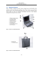
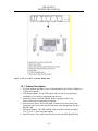
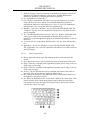
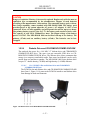
MIL-BOOK 1000 SERIES NOTEBOOK OPERATOR’ S MANUAL 22355 TAG Way, Dulles, VA 20166 Tel: (703) 406.3000 Fax: (703) 607.3853 MIL-BOOK™ OPERATORS MANUAL - ii - MIL-BOOK™ OPERATORS MANUAL © 2004 Technology Advancement Group®, Inc. (TAG®) All rights reserved. No part of this publication maybe reproduced by any means for any reason without express written approval from Technology Advancement Group®, Inc., or its authorized representative. Technology Advancement Group®, Inc. makes no representations, either express or implied concerning the accuracy of this manual. All the information contained herein is believed to be complete and reliable as of the printing date. Technology Advancement Group®, Inc. reserves the right to make changes to this manual or product specifications without obligation to notify any person of such changes. Technology Advancement Group, TAG, and the TAG ball graphic are registered trademarks of Technology Advancement Group Inc. MIL-BOOK is a trademark of Technology Advancement Group, Inc. IBM, IBM PC/AT and OS/2 are registered trademarks of International Business Machines Corporation. Intel Pentium is a registered trademark of Intel Corporation. MS-DOS, Windows 2000/Windows XP are registered trademarks of Microsoft Corporation. UNIX is a registered trademark of AT&T Bell Laboratories. Other brand and product names are trademarks and/or registered trademarks of their respective holders. - iii - MIL-BOOK™ OPERATORS MANUAL Class B Regulations Federal Communications Commission Radio Frequency Interference Statement NOTE: This equipment has been tested and found to comply with the limits for a Class B digital device pursuant to Part 15 of the FCC Rules. These limits are design to provide reasonable protection against harmful interference in a residential installation. This equipment generates, uses, and can radiate radio frequency energy and, if not installed and used in accordance with the instructions, may cause harmful interference to radio communications. However, there is no guarantee that interference will not occur in a particular installation. If this equipment does cause harmful interference to radio or television reception, which can be determined by turning the equipment off and on, the user is encouraged to try to correct the interference by one or more of the following measures: Reorient or relocate the receiving antenna. Increase the separation between the equipment and receiver. Connect the equipment into an outlet on a circuit different from that to which the receiver is connected. Consult the dealer or an experienced radio/TV technician for help. Any changes or modifications not expressly approved by the manufacturer could avoid the user’s authority to operate the equipment. Please note: 1. The use of a non-shielded interface cable with this equipment is prohibited. 2. A shielded AC power cord must be used with this equipment. - iv - MIL-BOOK™ OPERATORS MANUAL Products with the CE Marking comply with both the EMC Directive (89/336/EEC) and the Low Voltage Directive (73/23/EEC) issued by the Commission of the European Community. Compliance with these directives implies conformity to the following European Norms: • EN50081-1: Electromagnetic compatibility-Generic emission standard • EN55022: conducted Emission, Radiated Emission • EN61000-3-2: Current Harmonic • EN61000-3-3: Voltage Flicker • EN50082-2: Electromagnetic compatibility-Generic immunity standard • IEC1000-4-2: Electrostatic Discharge • IEC1000-4-3: Radiated Susceptibility • IEC1000-4-4: Electrical Fast Transients • IEC1000-4-5: Surge Test • IEC1000-4-6: Conducted Susceptibility • IEC1000-4-11: Voltage Dip and Interruption -v- MIL-BOOK™ OPERATORS MANUAL Preface This is the MIL-BOOK 1000 Series Notebook Operation Guide. Contents This manual contains information for personnel using the MIL-BOOK 1000 Series notebook computer. Readers should have a basic understanding of Windows 2000 or Windows XP operating system installed on the computer when reading this document. With the exception of the SETUP configuration program, which is part of the system firmware, this manual does not explain any of the software or devices used with the system. Supplemental manuals or text-based documents on the hard disk supply information about any software included with the system. Audience All operators using the notebook in or out of the field should read and become familiar with this manual. Organization This manual has four chapters. Chapter 1 introduces the notebook pointing out its major features. Chapter 2 explains daily operation. Chapter 3 gives detailed information about configuring the notebook. Chapter 4 introduces the notebook Maintenance. Supplemental Reading For further information about this computer and computing in general, use these references: MIL-BOOK 1000 Series Service Manual for detailed troubleshooting and repair instructions for serious hardware problems associated with the MIL-BOOK 1000 Series notebook. Various software manuals offer detailed instructions about individual programs run on the notebook. - vi - MIL-BOOK™ OPERATORS MANUAL Specifications (reference only) Standard Optional CPU Intel Pentium M Processor 1.4/1.6Ghz (µ-FCPGA) package RAM Display 256 MB 1. 12.1” color LCD, 64K color TFT, XGA 2. 13.3” color LCD, XGA TFT 3. 14.1” color LCD, XGA TFT 512MB or above 12.1” for Sun-Light Readable (Transflective) Keyboard 87-key shower proof and dust-proof rubber keyboard Embedded two-button Track Pad A toucn-senstive control pad with Microsoft Win Mouse function coexist LED Backlight Rubber Keyboard Device Point Support Glove hand Touch Pad Bay-1 Modules Swappable for CD-ROM, DVD,DVD-RW,FDD, Battery, 2nd HDD, COMBO drive Bay-2 Modules 2nd PCMCIA-Removable Type III x 1 or TYPE II x 2 Module COM port Module- Removable Sealed Water Proof RS-232, 422, or 485 Module DGPS- DGPS Module Bay2 Battery Pack- Removable and Recharge Li-Ion Battery Pack Bay2 FDD Wireless Modem (GSM/GPRS) Expansion Unit (PCI/ISA) Port replicator (SIOx2, PIOx1,USBx4,VGAx1, DC input, Power switch) Carrying Bag Shock Mount External battery charger (2-pcs and 3-pcs) 11-32VDC 90W car adapter USB external FDD 802.1 1b Wireless LAN - vii - MIL-BOOK™ OPERATORS MANUAL Standard Communication ports Battery pack Optional One serial port One parallel port, support EPP/ECP RJ-11 port RJ-45 port One VGA monitor port Two USB 2.0 One Port Replicator port One DC input port One infrared port IEEE 1394 port Mic-In and Line-Out Removable & rechargeable main Li-ion battery pack with the functions of on-line charge and hot swap. Primary battery pack 97 watts. Power adapter I/P: AC 100-240 V, 50-60 Hz O/P: DC 19V, ±5%, 4.74A, 90W , CV mode Operating system Removable & rechargeable Bay 1 Li-ion battery pack in Bay 1, total 65 watts Removable & rechargeable Bay 2 Li-ion battery pack in Bay 2, total 65 watts 9-12 VDC direct input without charging function 12-32 VDC external car adaptor/ charger Windows 2000 Windows XP Temperature • Operating: 0°C to +55°C • Non-operating: -40°C to 70°C (tested) Open Size: (With Rubber Bumper) 315mm W 70mm H 260mm D Weight 14.3 lbs (6.5 kg) - viii - • Option: -20°C to +55°C (tested) MIL-BOOK™ OPERATORS MANUAL Safety Summary 1. Read these instructions before using or working on this computer. 2. Follow all warnings and instructions in this manual or marks on the computer and its components. 3. Avoid submerging the system unit in liquids. 4. Avoid stacking papers or other flammable objects on top of, underneath, or next to the system unit. 5. Use only batteries supplied with the system. 6. Make sure any external power source connected to the adapter or system conforms with adaptor or system ratings. 7. The external power adapter has a two-pronged grounding plug. If an adapter is needed to plug the system into a power source, make sure the system is properly grounded. 8. Arrange all cables so that they are out of traffic and unobstructed by personnel or equipment. 9. Avoid using extension cords with this product. If an extension cord is needed, make sure it is rated for at least 10 amperes. 10. Make sure amperage drawn by all items plugged into an outlet with this system does not exceed 15 amperes. 11. Do not put any objects except those designed for use with this system inside the computer. 12. Observe proper electrical safety precautions when performing system maintenance. 13. Replace any cables with identically rated cables as those included with the original equipment. 14. Improper handling of the battery can cause personal injury or fires. Do not attempt to disassemble or replace individual cells in the battery pack. Do not expose the battery to open flames. Do not short the positive and negative ends together even if the battery is fully discharged. Keep the battery away from children. - ix - MIL-BOOK™ OPERATORS MANUAL Table of Contents CHAPTER 1. SYSTEM OVERVIEW 1-1 1.1 Introduction 1-1 1.2 System Description 1-1 1.3 System Configuration 1.3.1 Standard Configuration 1.3.2 Options and Accessories 1.3.2.1 Carrying Bag 1.3.3 System Identification 1-1 1-1 1-3 1-3 1-3 1.4 1-3 Unpacking 1.5 Notebook Features 1-4 1.5.1 Feature Description 1-5 1.5.2 Rear Components 1-6 1.5.3 The Keyboard 1-6 1.5.3.1 Keyboard Keys 1-7 1.5.3.2 Cursor Control Keys 1-8 1.5.3.3 Keyboard Touchpad 1-9 1.5.4 Additional Keyboard Functions 1-9 1.5.4.1 Volume Control 1-9 1.5.4.2 Brightness Control 1-10 1.5.4.3 Toggle Key (Option for RS485) 1-10 1.5.4.4 Keyboard Backlight (Option) 1-10 1.5.4.5 CRT/LCD/Simulscan Toggle 1-10 1.5.4.6 Panel On/Off 1-10 1.5.4.7 Toggle LCD Backlight On/Off (Option) 1-10 1.5.4.8 1-5.4.1 Hot Key Function 1-11 1.5.5 Status Row Indicators 1-11 1.5.6 Status Row Descriptions 1-12 1.5.7 The AC Power Adapter 1-12 1.5.8 Status Row 1-12 1.5.9 Battery Pack 1-13 1.5.10 Low Battery Indication 1-13 1.5.11 Battery Charger 1-14 1.5.12 CHARGE LED Indicator Status 1-14 1.5.13 Connections 1-14 1.5.14 Serial Port 1-14 1.5.15 Parallel Port 1-15 1.5.16 VGA Port 1-15 1.5.17 USB2.0 Port 1-15 1.5.18 IrDA Port 1-16 1.5.19 Replicator Port 1-16 1.5.20 Power Port 1-16 1.5.21 IEEE 1394 Port 1-16 1.5.22 Audio Connections 1-16 1.5.23 1-5.5 Battery Pack 1-16 1.5.24 Diskette Drive and CD-ROM/DVD/COMBO /DVD-RW 1-17 1.5.24.1 1-5.6.1 PCMCIA Slot and Diskette Drive and CD-ROM/DVD /COMBO/DVD RW Door 1-17 -x- MIL-BOOK™ OPERATORS MANUAL CHAPTER 2. 2.1 OPERATION 2-1 Introduction 2-1 2.2 Opening and Closing the Notebook 2.2.1 Opening the Cover 2.2.2 Closing the Cover 2.2.3 Opening the PCMCIA, FDD, CD ROM/DVD/COMBO, DVD RW Door 2.2.4 Closing the PCMCIA, FDD, CD ROM/DVD/COMBO, DVD RW Door 2-1 2-1 2-1 2-2 2-2 2.3 Connecting and Installing Devices 2.3.1 Serial and Parallel Port 2.3.2 External Power Adapter 2.3.3 Floppy Disk Drive/CD-ROM/DVD/COMBO/DVD RW 2.3.3.1 Replace the FDD/CD-ROM/DVD/COMBO/DVD RW: 2.3.4 Loading and Remove Diskettes 2.3.5 PCMCIA Cards 2.3.6 Hard Disk 2.3.7 Hard Disk Drive Module 2.3.8 IEEE 1394 2.3.9 EMI Accessory Descriptions 2-2 2-3 2-3 2-4 2-4 2-5 2-5 2-5 2-6 2-7 2-8 2.4 First Time Use 2.4.1 Installing Software Drivers 2.4.2 Install Device Driver for Windows 2000/Windows XP 2.4.3 Install Touch Screen Driver for Windows 2000 2.4.4 Installing Drivers for Windows XP 2.4.5 Install Touch Screen Driver for Windows XP 2-9 2-9 2-10 2-11 2-11 2-12 2.5 Daily Operation 2.5.1 Starting the Computer 2.5.2 Turning Off The Notebook 2.5.3 Using the Notebook in the Car 2-19 2-19 2-20 2-20 2.6 Using External Power Sources 2.6.1 Using AC External Adapter 2.6.2 Charging the Batteries 2-21 2-21 2-22 2.7 2-22 Running On Battery Power CHAPTER 3. 3.1 SETUP CONFIGURATION UTILITY Introduction 3-1 3-1 3.2 Running SETUP and Moving Around 3.2.1 Main 3.2.2 Moving Around and Making Selections 3.2.2.1 Main Menu 3.2.2.2 Date and Time 3.2.2.3 Internal Num Lock 3.2.2.4 USB Emulation 3.2.2.5 Keyboard Backlight 3.2.2.6 Advanced Menu 3.2.2.7 Geyserville Support - xi - 3-1 3-2 3-2 3-3 3-3 3-4 3-4 3-5 3-5 3-6 MIL-BOOK™ OPERATORS MANUAL 3.2.2.8 Share Video Memory 3.2.2.9 IR Ports 3.2.2.10 COM Ports 3.2.2.11 LPT Port 3.2.3 Security Menu 3.2.3.1 System Password 3.2.3.2 Hard Disk Boot Sector 3.2.4 Boot Menu 3.2.5 Exit Menu CHAPTER 4. 3-6 3-7 3-7 3-8 3-8 3-9 3-9 3-10 3-11 NOTEBOOK MAINTENANCE 4-1 4.1 Introduction 4-1 4.2 Daily Use 4-1 4.3 Battery Maintenance 4.3.1 Conserving Power 4.3.2 Changing the Battery Pack 4-1 4-1 4-1 4.4 4-1 Cleaning - xii - MIL-BOOK™ OPERATORS MANUAL Table of Figures FIGURE 1-1 FEATURES OF THE MIL-BOOK 1000 FIGURE 1-2 FEATURES OF THE MIL-BOOK 1000 FIGURE 1-3 I/O ACCESS DOOR OF THE MIL-BOOK 1000 FIGURE 1-4 REAR COMPONENTS FIGURE 1-5 KEYBOARD WITH EMBEDDED TOUCHPAD FUNCTIONS FIGURE 1-6 CURSOR CONTROL KEYS FIGURE 1-7 TRACK PAD POINTING DEVICE FIGURE 1-8 STATUS ROW LIGHTS FIGURE 1-9 AUXILIARY BATTERY PACK FIGURE 1-10 DISKETTE DRIVE AND CD-ROM/DVD/COMBO/DVD-RW FIGURE 2-1 OPENING THE NOTEBOOK FIGURE 2-2 OPENING A DOOR FIGURE 2-3 CONNECTING THE EXTERNAL POWER, SERIAL , AND PARALLEL FIGURE 2-4 CONNECTING THE EXTERNAL POWER ADAPTER FIGURE 2-5 REMOVING A FDD/CD-ROM/DVD/COMBO /DVD RW MODULE FIGURE 2-6 REMOVING A DISKETTE FIGURE 2-7 REMOVING A PCMCIA CARDS FIGURE 2-8 REMOVING A HARD DISK DRIVE MODULE FIGURE 2-9 REMOVING IEEE 1394 PORT FIGURE 2-10 EMI CORE & CABLE FIGURE 2-11 INSTALLING DRIVERS FIGURE 2-12 INSTALLING DRIVERS FIGURE 2-13 WINDOWS 2000 DRIVER FIGURE 2-14 CONTROL PANEL FIGURE 2-15 PERFORMANCE AND MAINTENANCE FIGURE 2-16 SYSTEM PROPERTIES FIGURE 2-17 DEVICE MANAGER FIGURE 2-18 UNKNOWN DEVICE PROPERTIES FIGURE 2-19 REINSTALL DRIVER FIGURE 2-20 HARDWARE UPDATE WIZARD FIGURE 2-21 HARDWARE INSTALLATION FIGURE 2-22 FINISH FIGURE 2-23 PENMOUNT DMC9000 PROPERTIES FIGURE 2-24 TOUCH SCREEN UTILITY FIGURE 2-25 PENMOUNT CONTROL PANEL FIGURE 2-26 USING THE MIL-BOOK 1000 IN THE CAR FIGURE 3-1 SCU SETUP FIGURE 3-2 MAIN MENU FIGURE 3-3 DATE AND TIME FIGURE 3-4 INTERNAL NUM LOCK FIGURE 3-5 USB EMULATION FIGURE 3-6 KEYBOARD BACKLIGHT FIGURE 3-7 GEYSERVILLE SUPPORT FIGURE 3-8 GEYSERVILLE SUPPORT FIGURE 3-9 SHARED VIDEO MEMORY FIGURE 3-10 IR PORTS FIGURE 3-11 COM PORTS FIGURE 3-12 LPT PORT FIGURE 3-13 SECURITY MENU FIGURE 3-14 POWER-ON PASSWORD FIGURE 3-15 HARD DISK BOOT SECTOR FIGURE 3-16 BOOT MENU FIGURE 3-17 EXIT MENU - xiii - 1-4 1-4 1-5 1-6 1-7 1-9 1-9 1-11 1-15 1-17 2-2 2-2 2-3 2-3 2-4 2-5 2-6 2-7 2-8 2-9 2-10 2-12 2-12 2-13 2-13 2-14 2-14 2-15 2-15 2-16 2-16 2-17 2-17 2-18 2-19 2-21 3-1 3-3 3-3 3-4 3-4 3-5 3-5 3-6 3-6 3-7 3-7 3-8 3-8 3-9 3-9 3-10 3-11 Chapter 1. 1.1 System Overview Introduction MIL-BOOK 1000 notebook computer is a new generation notebook computer. It is a high-end rugged notebook computer that is an industrial notebook with some rugged features such as vibration, shock, drop, and drip-proof. It is designed for using in vehicle or in the harsh environment. The MIL-BOOK 1000 notebook computer implements the new technologies in the industrial market. Large display panel, high capacity hard disk drive, PCI bus and CD-ROM, etc. An Intel Pentium M Processor 1.4/1.6GHz CPU is the heart of this notebook computer. This chapter introduces and explains the MIL-BOOK 1000 notebook and its computer parts. 1.2 System Description The MIL-BOOK 1000 computer is a compact fully portable notebook computer. It operates as a stand-alone system for most applications. It offers superior performance under harsh environmental and operating conditions. It is fully compatible with the IBM PC/AT standard. 1.3 System Configuration This section presents and explains possible notebook hardware configurations. Refer to the nameplate on the notebook bottom for that system's configuration. 1.3.1 Standard Configuration Table 1-1 lists the major common features of the standard MIL-BOOK 1000 systems. The specifications in this table may be different from yours due to the optional items. Please refer to the detailed specifications including the standard and optional configurations. MIL-BOOK™ OPERATORS MANUAL Feature Description CPU Intel Pentium M Processor 1.4/1.6 GHz or above Storage device Removable 2.5-inch hard disk drive Removable 3.5-inch 1.44 MB Floppy disk drive 1. 12.1/13.3”/14.1” TFT XGA LCD, Res. 1027X768 2. Optional: 12.1" Touch Screen 12.1” Sunlight Readable (Transflective LCD ) Primary Li-ion Type , Battery life for 5 hours. Bay1: Li-Ion Smart Battery Bay2: Li-Ion Smart Battery 87key shower proof rubber keyboard, Embedded two button track pad Optional : LED Backlight Rubber Keyboard Two PCMCIA sockets (type II or one type III compatible) One RS-232 serial port One Centronics parallel port, support EPP/ECP One VGA monitor port One RJ-11 port One RJ-45 port One Port Replicator port One DC input power supply port One infrared port Two USB2.0 port One 1394 Port One Mic-In and Line Out 315(w) x 260 (D) x 70 (H) mm 6.5 KG (14.3 lbs) Support Windows 2000/ Windows XP Display Battery Keyboard Expansion I/O Devices Dimensions Weight Software Table 1-1 Standard MIL-BOOK 1000 Notebook Computer - 1-2 - MIL-BOOK™ OPERATORS MANUAL 1.3.2 Options and Accessories (A) BAY 1 Options • CD-ROM • Bay 1 FDD • Bay 1 Battery Pack • DVD • DVD RW • COMBO Drive (DVD+CD-RW) (B) BAY 2 Options • RS-232/RS-422 • RS-485 • Wireless Modem (GSM/GPRS) • 2nd PCMCIA- Removable TYPE III x 1 or TYPE II x 2 Module • DGPS-DGPS Module • Bay2 Battery Pack – Removable and Rechargeable Li-lon Battery • Pack • Bay2 FDD 1.3.2.1 Carrying Bag The carrying bag makes carrying the notebook and its peripherals easier. It has compartments for up to four diskettes, this manual, the power supply, and all notebook cables. 1.3.3 System Identification The nameplate listing system information is at the bottom of the notebook. It contains: • Factory configuration • Model number • Serial number 1.4 Unpacking Use this checklist to make sure all items included with the notebook are present in good condition. • Notebook computer • Rechargeable battery pack • AC adapter • Power cord • Operation Manual • CD Driver If any items are missing or damaged, please contact TAG at (877) TAG-TECH or [email protected]. - 1-3 - MIL-BOOK™ OPERATORS MANUAL 1.5 Notebook Features Items 1 through 18 identify the major features designed into the MIL-BOOK 1000 computer. A brief description will accompany each call-out to help you get stated and become familiar with your MIL-BOOK 1000. Some of the features described in this section might vary from your individual MIL-BOOK 1000 due to the different configuration and optional items available. Figure 1-1 Features of the MIL-BOOK 1000 Figure 1-2 Features of the MIL-BOOK 1000 - 1-4 - MIL-BOOK™ OPERATORS MANUAL Figure 1-3 I/O Access Door of the MIL-BOOK 1000 1.5.1 Feature Description 1. Wireless Modem Antenna- Serves as the antenna for the Wireless Modem. It is built-in the handle. 2. LED Status Signals- Seven LED signals indicate the current operating conditions of several key components and devices. 3. Sealed Keyboard- The MIL-BOOK 1000 is equipped with 87 key shower/dust-proof sealed rubber keyboard. 4. Sealed Access Doors- Well sealed and secured access doors protect the expansion bays from water and dust intrusion when transporting the MILBOOK 1000. 5. Flat-Panel Display- The MIL-BOOK 1000 provides a sealed, non-glare 12.1/13.3/14.1” color flat-panel display. 6. On/Off Switch- This switch controls the power to the MIL-BOOK 1000. - 1-5 - MIL-BOOK™ OPERATORS MANUAL 7. Touchpad/Point Device- The keyboard is equipped with an embedded twobutton touchpad/point device. 8. Stereo Speakers- The MIL-BOOK 1000 is equipped with two stereo speakers for audio sound. 9. Carrying Handle-The durable carrying handle makes transportation of the MIL-BOOK 1000. 10. Opening Latch- The MIL-BOOK 1000 is equipped with a shock-proof, drop resistant opening latch. 11. LCD Rubber Bumpers- The shock absorbing corner bumpers protect the MILBOOK 1000 during transport and prevents slippage when operating in an upright open position. 12. Sealed I/O Access Doors- The sealed access doors on the rear panel protect the I/O ports from water and dust intrusion during transport of the MILBOOK 1000. 13. Bay 2 – An optional peripheral device of your choice can be installed in bay 2. 14. Removable Hard Disk Drive Module- The MIL-BOOK 1000 is equipped with a standard removable shock-proof hard disk drive module. 15. Removable Primary Battery- The MIL-BOOK 1000 is equipped with rechargeable and removable primary battery. 16. Audio jacks – Two audio jacks (line-out and mic-in) are provided on the MILBOOK 1000. 17. PCMCIA/CardBus slots – The MIL-BOOK 1000 provides two (2) Type II or one (1) Type III PCMCIA/CardBus slots for added expansion. 18. Removable Floppy Disk Drive Module – The MIL-BOOK 1000 is equipped with removable 3.5”, 1.44 MB floppy disk drive module. 1.5.2 Rear Components Figure 1-4 Rear Components 1.5.3 The Keyboard The MIL-BOOK 1000 is equipped with a completely sealed, 87-key rubber keyboard with twelve function keys and dedicated cursor keys. An embedded touchpad with two mouse buttons is centered below the keys. It eliminates the need for external mouse device. The touchpad is pressure sensitive and works by the touch and movement of your fingertip. - 1-6 - MIL-BOOK™ OPERATORS MANUAL Smoothly move your fingertip over the pad in the direction in which you want the cursor to move. Refer to the tables on the following pages for the main functions of the keyboard keys and helpful tips on use of the embedded touchpad. Figure 1-5 Keyboard with Embedded Touchpad Functions 1.5.3.1 Keyboard Keys Item Key Function 1. ESC - Cancels or escapes from a command or a function. 2. F1-F12 - The keys on the top row of the keyboard labeled F1 through F12 are called “function keys.” Special commands are defined for each key. Refer to the user’s manual, for a particular application program, to determine the function of each of three keys. The MIL-BOOK 1000 Bios also uses function keys to set some configuration parameters. 3. Numeric Lock - This key switches the number pad between acting as numeric keys or editing keys. When the keyboard “Num Lock” indicator is lit, the number pad is active. 4. Prt SC Sys Req - Sends the information currently showing on the display to a connected printer. Pressing this key in conjunction with the <Ctrl> key sends all output to a connected printer. Press this key combination again to stop the function. 5. Back Space Deletes characters as it moves the cursor to the left. Use it to correct typing mistakes. 6. Scroll Lock In some applications, information will move across the screen differently when this key is engaged. It can change the text scroll up and down feature. 7. Pause Break Temporarily halts a running program. To continue using the program again, press any key. Pressing the “Pause” key in conjunction with the <Ctrl> key breaks the program. 8. Tab Moves the cursor horizontally to the next tab stop. - 1-7 - MIL-BOOK™ OPERATORS MANUAL 9. Numeric Keypad - These keys function as calculator keys when the “Num Lock” indicator is lit. When the numeric keypad is active, the MIL-BOOK 1000 disables the alphabet keys doubling as numeric keypad keys. 10. Fn - An additional “Function Key”. 11. Ctrl - Works in combination with other keys to provide shortcuts or to modify actions. Refer to the user’s manual, for a particular application program, to determine the function of each of these keys. To use a <Ctrl> key combination, hold down the <Ctrl> key and the other key simultaneously. 12. Windows - One of two “Windows” key provided on the MIL-BOOK 1000. The “Windows” logo key is used in conjunction with other keys to perform software specific functions. 13. Alt - The MIL-BOOK 1000 provides two “Alt” keys. Works in conjunction with other keys to perform various commands or functions. Refer to the user’s manual, for a particular application program, to determine the function of each of these keys. 14. To use an “Alt” key combination, hold down the <Alt> key along with the other key. 15. Application - One of two “Windows” keys provided on the MIL-BOOK 1000. The “Application” key is used in conjunction with other keys to perform software specific functions. 1.5.3.2 Cursor Control Keys Item Key Function 16. Home - Moves the cursor to the first character position on the top line of the screen. 17. End - Moves the cursor to the last character position on the bottom of the screen. 18. PgUp - If this key is operable in the application program you are using, it lets you scroll to the previous page. 19. PgDn -If this key is operable in the application program you are using, it lets you scroll to the next page. 20. Arrows - The four direction arrow keys control the movement of the cursor on the screen. They do not affect the displayed character keys. 21. Del - Deletes the character to the right of the cursor. All remaining characters to the right move one space to the left. 22. Ins - Places the keyboard into the “insert mode”. While in the “insert mode”, data entries are made at the current cursor position and all data to the right of the cursor position moves to the right. The keyboard stays in the insert mode until you press the “Insert” key again. - 1-8 - MIL-BOOK™ OPERATORS MANUAL Figure 1-6 Cursor Control Keys 1.5.3.3 Keyboard Touchpad The built-in touchpad is a convenient substitute for a mouse device. It’s function is similar to that of a two-button mouse. The left button is equivalent to the left button on a mouse and the right button is equivalent to the right button on a mouse. The touchpad is capacitive, and needs to be in contact with your skin to operate. • • • • To move the cursor: Place your thumb or finger on the surface of the touchpad and move it in the direction you with the cursor to go. To Click: Press the touchpad’s left or right button or lightly tap on the touchpad. To double click: Either press the button twice or lightly tap the touchpad twice in quick succession. There are two ways to drag: Move the cursor to the desired location, the press down the left button. While still holding down the left button, move the cursor to the desired location. Then, release the button. Move the cursor to the desired location. Quickly tap the touchpad as if you were double clicking however, do not move your finger after the second tap. While maintaining contact with the touchpad, move the pointer to the desired location. Lift your finger to complete the move. Figure 1-7 Track Pad Pointing Device 1.5.4 Additional Keyboard Functions The MIL-BOOK 1000 offers “Hot Key” commands that provide easy access to system features. The use of the “Fn” key along with several specific keys (F1F12) controls various functions of the MIL-BOOK 1000. 1.5.4.1 Volume Control The volume control is adjusted by use of a combination of function keys. To increase the volume, press the Fn+F4 keys. To decrease the volume, press the - 1-9 - MIL-BOOK™ OPERATORS MANUAL Fn+F3 keys. The “Hot Key Beep” function of these keys will not be supported to avoid interface with the normal sound effect. NOTE The system does not support the Fn+F3 and the Fn+F4 volume control function when using the DOS program. 1.5.4.2 • The brightness control is adjusted by use of a combination of function keys. Press the Fn+F5 keys to darken the screen image. Press the Fn+F6 keys to brighten the screen image. To further adjust the screen image, press and hold down the “Fn” key and continue to repeatedly press either the “F5” key or the “F6” key until you obtain the desired brightness. If you press the Fn+F5 or the Fn+F6 keys to adjust the LCD brightness and continue to adjust the screen image when it is already set to either the minimum or the maximum setting, the system will keep on beeping each time the “F5” or the “F6” key is pressed. 1.5.4.3 • Panel On/Off The turn the panel “On” and “Off”, press the Fn+F10 keys. 1.5.4.7 • CRT/LCD/Simulscan Toggle The switch between the CRT/LCD/Simulscan display modes, press the Fn+F9 keys. 1.5.4.6 • Keyboard Backlight (Option) The turn the keyboard backlight “On” and “Off” press the Fn+F8 keys. 1.5.4.5 • Toggle Key (Option for RS485) The Hot Key is Fn +F7 to toggle the RX/TX direction. 1.5.4.4 • Brightness Control Toggle LCD Backlight On/Off (Option) The Toggle LCD backlight selected pressing the function keys Fn+F11. Usually use Fn +F11 function key for transflective LCD panel. NOTE Fn + F11 function only can use on system working status. If system resume from S1(idle), S2 (idle), S3 (Suspend to RAM), S4 (Suspend to Disk) then the LCD Backlight always on. - 1-10 - MIL-BOOK™ OPERATORS MANUAL 1.5.4.8 1-5.4.1 Hot Key Function Keys Fn+F3 Fn+F4 Fn+F5 Fn+F6 Fn+F8 Fn+F9 Feature Volume Down Volume Up Brightness Down Brightness Up Keyboard Backlight LCD/External CRT Switching Fn+F10 Fn+F11 LCD panel toggle on/off LCD Backlight On/Off Fn+F12 System Sleep Description Decrease the volume. Increase the volume. Decreases the LCD brightness. Increases the LCD brightness. Switches the keyboard backlight On/Off. Switches the display mode to LCD only, CRT only or simultaneously display (LCD/CRT). Switches the flat-panel On/Off. Toggle Backlight On/Off. (Transflective LCD only) System sleep button function. (For user define) Table 1-2 Hot Key Function 1.5.5 Status Row Indicators The “Status Row Indicators” keeps you informed of the computer’s operating status. The LED’s light up to show the current operating condition of several key MIL-BOOK 1000 devices and features. Figure 1-8 Status Row Lights - 1-11 - MIL-BOOK™ OPERATORS MANUAL 1.5.6 Status Row Descriptions Scroll Lock Caps Lock Num Lock HDD, FDD, CD Batt Exist, Batt Low AC/IN Charge Power On, Suspend This light indicates that the keyboard is in the “Scroll Lock” mode. The “Scroll Lock” key works with some program to freeze the display. This light indicates that the keyboard is in the “Caps Lock” mode. In this mode, the keyboard produces only upper case text when you press the keys. This light indicates that the keyboard in the “Num Lock mode. This key activities and de-activates the embedded numeric keypad provided on the keyboard. The Orange “HDD” light indicates that the system is accessing the hard disk drive. The orange “FDD” light indicates that the system is accessing the floppy disk drive. And the orange “CD” light indicates that the system is accessing the CD-ROM drive. The green “Batt Exist” light indicates that the battery pack installed. The orange “Batt Low” light indicates that the installed battery pack is entering a low battery status mode. The green “AC/IN light indicates that the system is “On” and the AC adapter is connected. Charging is in progress when the orange “Charge” light is lit. When the battery is fully charged, the orange “Charge” light goes off. The green “Power On” light indicates that the system is power “On”. The orange “Suspend” blinks indicates that the system is in a suspend mode. Table 1-3 Status Row Descriptions 1.5.7 The AC Power Adapter The AC power adapter is the primary power source for the MIL-BOOK 1000. In order to reduce the power of the battery pack and keep it at full capacity, connect the AC power adapter to the system as frequency as possible. 1.5.8 Status Row The “Status Row” (Figure 1-8) keeps you informed of the computer’s operating status. The LEDs light up show the current operating condition of several key MIL-BOOK 1000 devices and features (See Fig 1-8). 1. When the power is on, then Power LED (Green) is on. 2. When the AC power adaptor is connected, then the AC IN LED (Green) is on in power stage. 3. When charging is in progress, then the CHARGE LED (Orange) is on in power on and off stage. When the battery is fully charged, the CHARGED LED (Orange) goes out. - 1-12 - MIL-BOOK™ OPERATORS MANUAL 4. When any battery pack is present, then the BATTERY LED (Green) is on in power stage. 5. When the optional battery pack ( Bay 1 or Bay 2) enters battery low status, then the BATTERY LOW LED (Orange) is on. When if only the primary battery and battery low status then speaker will beep and blinks. 6. When the HDD, FDD or CD-ROM/DVD/COMBO/DVD RW drive is active, then the HDD/FDD/CD/DVD/COMBO/DVD RW LED (Orange) is on. 7. The “Num Lock” key activates and deactivates the embedded numeric keypad. When the numeric keypad is active, the “Num Lock” indicator come on and the alphabetic of the embedded numeric keypad are disabled. 8. Press “Caps Lock” key will Charge the state of “Caps Lock” indicator between on and off, if the Caps Lock indicator goes on, represents the all English alphabet keys work in Upper Case state, otherwise the keys work in Lower Case state. 9. The “Scroll Lock” key works with some software to freeze the display. Then the cursor can move about the screen without the top bottom or any lines in between moving. 1.5.9 Battery Pack The removable battery pack, with on-line charge capability, comes standard with the MIL-BOOK 1000. The battery pack provides power to the system when the AC power is “Off” or not connected. The primary battery type is Li-ion. At 4.2V, the battery pack consists of twelve cells. The capacity of each cell is 2200 mAH or more. The output voltage of the battery pack is 11.1V. The MIL-BOOK 1000 can be fitted with up to two batteries. The primary battery is 97whr and an auxiliary battery is 65whr. The batteries can be hot-swapped. 1.5.10 Low Battery Indication When the battery voltage falls under the low battery status, the system will beep or the orange “Battery Low” LED status indicator will come on. • • • When the optional battery pack (in Bay 1 or 2) enters into low battery status, the orange “Battery Low” LED will come on. When the primary battery pack enters into low battery status, the system will beep and blinks in DOS mode. If Bay 1 or Bay 2 battery is in battery low status system just only have battery low LED indicate in orange, if primary battery is in battery low status system will have battery low beep indication. - 1-13 - MIL-BOOK™ OPERATORS MANUAL 1.5.11 Battery Charger The battery charger controls the current to the battery pack to charge batteries when necessary. The necessity for a charge cycle is usually determined each time the AC power is applied or the battery pack is inserted and connected to the system. The battery pack in the MIL-BOOK 1000 can be charged during both the power ”On” and “Off” stages. Two charge mode are provided when the AC power adapter is connected to the system. When the power is “Off”, a fast charge mode is activated with a constant current for the primary battery pack. The charge time for the primary battery pack is about 3.5 ~ 4 hours. When the power is “On”, an alternate charge mode is activated for the primary battery pack with fluctuating current according to the system load. The alternative charge time for the primary battery pack is about 5.5 ~ 6.5 hours. As for the auxiliary battery pack, the charge current is 1.4 ~ 1.6A and the charge time is about 3 ~ 4 hours whether the power is “On” and “Off”. 1.5.12 CHARGE LED Indicator Status 1. When you insert the battery pack into the system and the AC power adapter is already connected, the CHARGE LED (Orange) flashes three seconds or more and then stays “On” during the charge period. 2. When no battery pack is installed or the AC power adapter is not connected, the orange CHARGE LED remains is “Off”. 1.5.13 Connections To expend your computing capabilities, the MIL-BOOK 1000 is equipped with several interface ports and connection receptacles. These connectors support a variety of external peripheral devices. 1.5.14 Serial Port The MIL-BOOK 1000 includes one standard 9 pin D-type, RS-232C serial port for connecting a serial mouse or other external serial devices. The D-type connector is dedicated to the COM1 address. The serial port is located on the rear panel of the MIL-BOOK 1000. - 1-14 - MIL-BOOK™ OPERATORS MANUAL Figure 1-9 Auxiliary Battery Pack 1.5.15 Parallel Port The MIL-BOOK 1000 includes a 25-pin, D-type parallel port for connecting a parallel printer or another external parallel device, such as an external floppy disk drive. The parallel port supports both EPP/ECP functions. The parallel port is located on the rear panel of the MIL-BOOK 1000. 1.5.16 VGA Port The MIL-BOOK 1000 includes one 15-pin, sub-D VGA analog port for connecting an external monitor. It is accessible on the rear panel of the MILBOOK 1000. It is not necessary to connect an external monitor to the MIL-BOOK 1000, but by using an external, you can achieve higher resolutions than on the internal flat panel display. 1.5.17 USB2.0 Port The MIL-BOOK 1000 provides a USB2.0 (Universal Serial Bus) port for connecting USB compliant devices. Most peripheral devices require the user to shutdown the system, plug in the device and restart the system in order to use the new device. USB devices can be conveniently connected and disconnected while the system is running. The USB port transfers data at 480 MB/sec. Please refer to the device-specific documentation for information on connecting and using USB devices. The USB port is located on the rear panel of the MIL-BOOK 1000. - 1-15 - MIL-BOOK™ OPERATORS MANUAL 1.5.18 IrDA Port The MIL-BOOK 1000 provides an IrDA port, on the rear panel, for connecting an IrDA-compliant device port provides wireless support for your system. You can use this port to quickly transfer large amounts of data to another IrDA-compliant system or device. This port complies with all IrDA standards. 1.5.19 Replicator Port An 80-pin replicator port is provided on the rear panel of the MIL-BOOK 1000. This port expends two SIO, two USB2.0, PIO and a VGA port. Use the replicator port to connect your MIL-BOOK 1000 into docking station. The docking station controls the power and provides connections to all of the external devices for your MIL-BOOK 1000 in one easy hook-up. 1.5.20 Power Port If the MIL-BOOK 1000 is to be in use for an long continuous period, connect the external power adater into the power port. Then plug the power cord into a 3prong grounded wall socket to provide external power to the MIL-BOOK 1000. The power port is located on the rear panel of the MIL-BOOK 1000. 1.5.21 IEEE 1394 Port The MIL-BOOK 1000 provides a standard IEEE 1394 port for high speed connections. The “High Speed Serial Bus” is located on the right side panel, next to the audio jacks. 1.5.22 Audio Connections The MIL-BOOK 1000 comes standard with two speakers and two audio hook-up jacks. The jacks are located on the right side of the MIL-BOOK 1000, adjacent to the PCMCIA slots. 1.5.23 1-5.5 Battery Pack The primary battery is Li-Ion type. The capacity of each cell is 2200mAH or more. 3.7V, 12 cells are used in one pack. The output voltage of the battery pack is 11.1VDC, so the battery pack provides 97 watts or more to the notebook computer. The battery pack connector board provides the interface between the battery cells and DC/DC board. - 1-16 - MIL-BOOK™ OPERATORS MANUAL CAUTION Danger of explosion if battery is incorrectly replaced. Replace only with the same or equivalent type recommended by the manufacturer. Dispose of used batteries according to the manufacturer’s instructions. The removable battery pack, with online charge capability, comes standard with MIL-BOOK 1000. The battery pack provides power to the system when the AC power ( AC adapter) is “Off” or not connected. It has a 97whr capability and will operate the unit for up to two hours. The primary battery type is Li-ion. At 3.7V, the battery pack consists of twelve cells. The capacity of each cell is 2200mAH or more. The output voltage of the battery pack is 11.1VDC. The MIL-BOOK 1000 can be fitted with up to two battery. The primary (97whr) and an auxiliary battery (65whr). The batteries can be hotswapped. 1.5.24 Diskette Drive and CD-ROM/DVD/COMBO /DVD-RW The notebook has space for a 1.44 MB, 3.5” diskette drive and CDROM/DVD COMBO/DVD RW drive. The space can put removable FDD drive or CDROM/DVD/COMBO DVD RW drives. The diskette drive allows permanent data storage in a compact, transferable media. Data stored on diskettes can be easily passed from one machine to another. The MIL-BOOK 1000 Series diskette drive accepts 3.5” double-density (720 KB) and high density (1.44 MB) diskettes. 1.5.24.1 1-5.6.1 PCMCIA Slot and Diskette Drive and CD-ROM/DVD /COMBO/DVD RW Door The PCMCIA slot and diskette drive and CD-ROM/DVD/COMBO/DVD RW door (Item 1, Figure 1-10) protects the PCMCIA interfaces and diskette drive from damage in harsh environments. Figure 1-10 Diskette Drive and CD-ROM/DVD/COMBO/DVD-RW - 1-17 - Chapter 2. 2.1 Operation Introduction The rugged MIL-BOOK 1000 is a high-end, industrial notebook with lots of features andoptions. It is designed for harsh outdoor use as well in-vehicle use. This all-metal, portable system performs in ever-changing environments and in high-vibration, industrial areas. The MIL-BOOK 1000 can be powered by the MIL-BOOK 1000 adapter or by the rechargeable battery pack. This chapter will cover the operation of the MIL-BOOK 1000. The MIL-BOOK 1000 supports a wide range of external peripheral devices. Installation instructions and procedures for these devices will also be covered in this chapter. The MIL-BOOK 1000 provides two compartment bays for optional removable device modules and PCMCIA CardBus slots for add-in expansion. 2.2 Opening and Closing the Notebook This section provides instructions for opening up and closing the MIL-BOOK 1000. Instructions for removing and replacing all of the access doors and covers around the MIL-BOOK 1000 will also be covered in this section. 2.2.1 Opening the Cover To open the notebook, press hook outward and tilt the cover up to a comfortable viewing angle. (Usually about 110°) See Figure 2-1. 2.2.2 Closing the Cover Be sure to turn the system “Off” and disconnect the power before closing the cover. If not, the system will stay “On” when you close the cover. Push the cover down until it clicks shut. Push in on the latch to secure it. MIL-BOOK™ OPERATORS MANUAL Figure 2-1 Opening the Notebook 2.2.3 Opening the PCMCIA, FDD, CD ROM/DVD/COMBO, DVD RW Door Open doors only when it is required to access components behind them. To open a door: 1. Insert a small flat edged object (a small sized screwdriver or the edge of a small coin) into the slot of one of the captive screws securing the access door. 2. Turn the screw counter-clockwise until it comes loose from its socket. 3. Repeat steps 1 and 2 for each screw securing the access door. 4. Use the handle to open the access door. If the access door does not have a handle, use one of the loosened screws to pull open the door. Figure 2-2 Opening a Door 2.2.4 Closing the PCMCIA, FDD, CD ROM/DVD/COMBO, DVD RW Door Be sure to close and secure the access doors before transporting the MIL-BOOK 1000. 1. Shut the door or put the PCMCIA/FDD/CD-ROM/DVD/COMBO/DVD RW back in place. 2. Align the door or cover securing screws with their sockets. 3. Use your finger to hold the screw in place. Insert a small flat-edged object ( a small sized screwdriver or the edge of a small coin) into the slot of one of the securing screws and turn clockwise until tight. 4. Repeat step 2 and 3 for each securing screw. 2.3 Connecting and Installing Devices This section gives instructions for installing, removing, changing, or connecting devices via the notebook external ports or sockets. - 2-2 - MIL-BOOK™ OPERATORS MANUAL 2.3.1 Serial and Parallel Port Use the “Serial” port to connect a serial device and the “Parallel” port to connect a parallel device (usually a printer or an external floppy disk drive) into the MILBOOK 1000. Item 1, Item2, Figure 2-3 shows how to connect serial and parallel cables. Make sure the mating connector is tightly secured by pushing it to the end and lock the screws. Insert the connector into the appropriate port, being careful not to bend the pins. Secure the two thumb screws one each side of the connector. Figure 2-3 Connecting the External Power, Serial , and Parallel 2.3.2 External Power Adapter Use the provided AC adapter to supply your MIL-BOOK 1000 with power form an external source. The MIL-BOOK 1000 can either be “On” or “Off” when connecting or disconnecting the AC adapter. Item 3, Figure 2-3 shows how to connect the power adapter. Make sure the mating connector is tightly secured by pushing it to the end. 1. Plug the connector from the AC adapter into external power port on the rear panel of the MIL-BOOK 1000. (See Fig 2-4) 2. Now, plug the power cord into the adapter. 3. Plug the other end the power cord into a 3-prong wall outlet or power strip. Figure 2-4 Connecting the External Power Adapter - 2-3 - MIL-BOOK™ OPERATORS MANUAL 2.3.3 Floppy Disk Drive/CD-ROM/DVD/COMBO/DVD RW Bay 1 on the MIL-BOOK 1000 can contain either a removable floppy disk drive, a removable CD-ROM, a removable DVD module or an auxiliary battery pack. 1. Turn the MIL-BOOK 1000 “Off”. 2. Open the Bay 1 access door. (See Fig 2-5) 3. Push down on the “Eject” handle at the bottom of the FDD/CD-ROM /DVD/COMBO/DVD RW compartment. Then FDD/CD-ROM/DVD /COMBO/DVD RW module will spring back about 0.4 cm. 4. Pull the handle outwards about 3 cm. Do not force it out any further as it might damage the unit. 5. Using both hands, gently slide the entire FDD/CD-ROM/DVD/COMBO /DVD RW module out form the bay 1 compartment. 2.3.3.1 Replace the FDD/CD-ROM/DVD/COMBO/DVD RW: Using both hands, gently insert the FDD/CD-ROM/DVD/COMBO /DVD RW module back into the bay 1 compartment. Continue to slide it in unit it seats firmly in place. Be sure to closed and secure the bay 1 access door when not in use. Turn the power back “On” to the MIL-BOOK 1000. NOTE Do not “Hot Swap” the FDD/CD-ROM/DVD/COMBO /DVD RW module. The MILBOOK 1000 is not PnP (Plug and Play) ready. Figure 2-5 Removing a FDD/CD-ROM/DVD/COMBO /DVD RW Module - 2-4 - MIL-BOOK™ OPERATORS MANUAL I 2.3.4 Loading and Remove Diskettes To install a diskette, 1. Open the PCMCIA slot/ diskette drive access door. 2. Slide the diskette into the drive with the printed label facing up until it clicks in place. 3. Press the “Eject” button, on the right side of the floppy drive to remove the diskette. See Figure 2-6. 2.3.5 PCMCIA Cards The MIL-BOOK 1000 comes standard with PCMCIA Card Bus slots for added expansion. The PCMCIA Card Bus slots support two type-II or one type-III PC card. Since both type II slots are co-located in the same opening, one type III PC card can be inserted instead of two type II PC cards. The type III PC card occupies both slots. The MIL-BOOK 1000 supports “hot insertion”. You can insert the PC card into the slot while the system is powered “On”. 1. Open the PCMCIA slot/diskette drive door. 2. Slide the card into the slot with the insert marking facing up until it seats. 3. To remove the upper card, press the eject button on the left. To remove the lower card, press the button on the right. (See Figure 2-7). Figure 2-6 Removing a Diskette 2.3.6 Hard Disk NOTE Installing or removing a hard disk when the computer is on can destroy the system board and hard disk. - 2-5 - MIL-BOOK™ OPERATORS MANUAL Figure 2-7 Removing a PCMCIA Cards 2.3.7 Hard Disk Drive Module To remove and replace the HDD module. NOTE Installing or removing a hard disk when the computer is “On” can destroy the system board and hard disk. 1. Turn the MIL-BOOK 1000 “Off”. 2. Loosen the captive screws securing the access door. 3. Use the handle on the access door to carefully pull the HDD module out and away from the MIL-BOOK 1000 (See Fig 2-8). 4. Insert the new Hard module into the slot. Gently push the HDD module in, until it seats firmly in place. Secure the captive screws on the access door. Turn the power back “On” to the MIL-BOOK 1000. 5. If necessary, run the system configuration utility, to set up or make any changes to the HDD drive parameters. See Chapter 3 for details. - 2-6 - MIL-BOOK™ OPERATORS MANUAL Figure 2-8 Removing a Hard Disk Drive Module 2.3.8 IEEE 1394 The MIL-BOOK 1000 provides a standard IEEE 1394 Fire Wire port for highspeed connections. The “High Speed Serial Bus” is located on the right side panel, next to the audio jacks. • • • • • • • • IEEE 1394-1995 Compliant and Compatible with Proposal 1394A 3.3V Core Logic with Universal PCI Interface Compatible With 3.3V and 5V PCI Signaling Environments Compliant to Latest PCI Specification ,PCI 2.2 PCI Power Management Compliant c Cable Power Presence Monitoring Low Cost 24.576MHz Crystal Provides Transmit, Receive Data at 100/200/400 Megabits per Second, and Link-Layer Controller Clock at 49.152 MHz Fully Interoperable with FireWire Implementation of IEEE Standard 1394 Provides 6-Pin IEEE1394 Standard Connector*1 NOTE The length of the cable for IEEE 1394 port must be less than 4.5m or the system will not support it. The system supports 15W power for the cable. - 2-7 - MIL-BOOK™ OPERATORS MANUAL Figure 2-9 Removing IEEE 1394 Port 2.3.9 EMI Accessory Descriptions The user can use the following EMI Accessories for better EMI protection. 1. EMI Core There are one same EMI cores. One is used to directly wrap around the 1394 cable of the user near the 1394 port side. NOTE The cores should be put close to the computer side for best performance. 2. EMI Cable There are two same EMI cables. One is for the microphone port and the other is for the speaker port. The male connectors are connected to the microphone and speaker ports, and the female connectors are connected to the microphone and speaker(s). 3. Modem Cable One modem cable together with the EMI core is used for the modem port. NOTE The connector close to the EMI core should be connected to the modem port of the computer for best performance. - 2-8 - MIL-BOOK™ OPERATORS MANUAL Figure 2-10 EMI Core & Cable 2.4 First Time Use The MIL-BOOK 1000 comes from the manufacturer with a dead battery. The first time you power “On” the MIL-BOOK 1000, you must use the AC adapter along with an outside power source. Once the main battery pack receive a full charge, you can use it to power the MIL-BOOK 1000. For more information about the battery, refer to “Charging the Battery” later in this chapter. 1. Insert the rechargeable battery pack into the battery compartment. 2. Plug the connector from the AC adapter into the external power port on the rear panel of the MIL-BOOK 1000. Now, plug the power cord into the adapter. 3. Plug the other end of the power cord into grounded 3-prong wall outlet of power strip. 4. Turn “On” the MIL-BOOK 1000. 2.4.1 Installing Software Drivers To take full advantage of the unique features of your computer, some operating systems require custom software, known as drivers, to be installed. If you purchased the computer with Windows pre-installed, TAG may have already installed the drivers. If not, you need to install the drivers using the driver CD supplied with your MIL-BOOK 1000. This section describes how to install the drivers. - 2-9 - MIL-BOOK™ OPERATORS MANUAL NOTES: The drivers may have been updated after this manual was published. For driver’s upgrade, please contact your dealer. You can always find README or document files on the CD. These files contain the latest information from the software supplier. Please read the files together with this chapter. This driver CD supports Windows 2000 and Windows XP only. The available items may differ according to your computer model and Operating System. NOTE: If driver CD version is not the same as the one shown on the Operation Manual, please refer to the User Guide file on the driver CD for the latest driver installation action steps and sequence. 2.4.2 Install Device Driver for Windows 2000/Windows XP To install the necessary driver, just click on the particular option and follow the onscreen instructions to continue and complete installation. Figure 2-11 Installing Drivers - 2-10 - MIL-BOOK™ OPERATORS MANUAL Device Driver 1. Press the “Device driver” button, the system will auto install include VGA, Audio, Modem, LAN , Wireless LAN, USB 2.0, DirectX 8.1, Chipset driver. 2. VGA Allows you to select high-resolution displays with richer colors. It can drive CD displays as well as CRT displays. 3. Audio Allows you to take full advantage of the audio subsystem. 4. Modem The modem driver allows you to transmit information over a standard telephone line through RJ-11 port. 5. Speedstep Press the Speedstep button, the system will auto install for Window 2000. 6. LAN/Wireless Allows you to use the network function of the computer. 7. USB 2.0 Allows your system to connect to USB 2.0 devices. 8. DirectX 8.1 Allows you to take full advantage of the multimedia applications. 9. Chipset Ensures the full function of the following drivers. Install this main chipset driver installing the device drivers. 10. Touchscreen Allows you to use your fingers as a pointing device on the LCD screen (refer to the next section for further instructions). 2.4.3 Install Touch Screen Driver for Windows 2000 1. Insert the driver CD into the drive. 2. Click on “TOUCH SCREEN” then “WIN2000”, and follow the onscreen instructions to continue. 3. When finished installing, select “Yes” to reboot your system. The driver should now be loaded. 4. After the system has finished rebooting, click on the “PenMount Monitor” icon located on the taskbar to bring up the “PenMount Control Panel.” 5. Select the “ Standard Calibration” folder and click on “OK” button. 6. If you need 4,9,16,25 dot of the calibrate, we suggest select “Advanced Calibration” button to calibrate. 7. Click on the four sides (points) and the plus-sign “+” on the screen to calibrate your touch screen pen for use on the computer. 2.4.4 Installing Drivers for Windows XP To set up the necessary drivers for Windows XP, click on “TOUCH SCREEN” on the initial screen. The following screen appears: - 2-11 - MIL-BOOK™ OPERATORS MANUAL Figure 2-12 Installing Drivers 2.4.5 Install Touch Screen Driver for Windows XP Hardware Install: Figure 2-13 Windows 2000 Driver 1. Insert the driver CD to the CD drive, to bring up the following screen. Select “WINXP”. - 2-12 - MIL-BOOK™ OPERATORS MANUAL Figure 2-14 Control Panel 2. When the TSRC-XP.htm file appear, then select ”START” -> “Control Panel” button. Figure 2-15 Performance and Maintenance 3. When the “Control Panel” screen appears, then click on “performance and Maintenance” button. - 2-13 - MIL-BOOK™ OPERATORS MANUAL Figure 2-16 System Properties 4. When the “Performance and Maintenance” screen appear, and then click on “System” button. Figure 2-17 Device Manager 5. When the “System Properties” screen appear, and then click on “Hardware” and “Device Manager” button - 2-14 - MIL-BOOK™ OPERATORS MANUAL . Figure 2-18 Unknown Device Properties 6. When the “Device Manager” screen appear, then click on “Unknown device” and then click on the “Properties” icon. Figure 2-19 Reinstall Driver 7. When the “Unknown Device Properties” screen appear, and then click on “ Reinstall Driver” button. - 2-15 - MIL-BOOK™ OPERATORS MANUAL Figure 2-20 Hardware Update Wizard 8. When the “Hardware Update Wizard” appears, click on “Install the software automatically [Recommended], then click on “Next”. Figure 2-21 Hardware Installation 9. When the “Hardware Installation” screen appears, click on ”Continue Anyway”. - 2-16 - MIL-BOOK™ OPERATORS MANUAL Figure 2-22 Finish 10. When the “Hardware Update Wizard” screen appears, click on “Finish” button. Figure 2-23 PenMount DMC9000 Properties 11. When the “PenMount DMC9000 and DMC9100 Properties” screen appears, click on “Close” button to exit the driver installation. - 2-17 - MIL-BOOK™ OPERATORS MANUAL Figure 2-24 Touch Screen Utility Touch screen Utility To install the touch screen utility, perform the following: 1. Insert the driver CD to the CD drive, to bring up the following screen. 2. Click on “Start” then “Run”. 3. Enter the following directory on the driver CD: \TOUCHSCREEN\Setup.exe, then click on “OK”. 4. Select “Yes” to the question if this is the first time to run this setup. 5. When the “Install Shield Wizard” appears, click on “Next” to continue. 6. Select “I accept the terms in the license agreement,” then click on “Next”. 7. When the “Ready to Install the Program” screen appears, click on “Install” to continue. 8. Reboot the system. 9. After the system has restarted, click on the “PM” icon located on the lowerright portion of your taskbar to bring up the “PENMOUNT Control Panel”. 10. When the “PENMOUNT Control Panel” dialog box appears, click on the “Calibrate” folder and click on the “Standard Calibration” button. - 2-18 - MIL-BOOK™ OPERATORS MANUAL Figure 2-25 PenMount Control Panel 11. If you need 4,9,16,25 dot of the calibrate, we suggest select “Advanced Calibration” button to calibrate. 12. Click on the four sides red points and plus sign on the screen to calibrate your “PENMOUNT” pen to start using your MIL-BOOK 1000’s Touch screen. 2.5 Daily Operation This section discusses expected daily notebook activity. 2.5.1 Starting the Computer To start the computer : 1. Make sure all peripherals are properly connected. 2. If using the AC adapter or external power, make sure it is connected. 3. Open the cover. 4. Press the Power button. The power on indicator lights up. The computer performs a Power On Self Test (POST) and checks configuration settings. Depending on the configuration, items tested include : o o o o o o o system board system DRAM video controller keyboard controller I/O controllers hard disk diskette drive - 2-19 - MIL-BOOK™ OPERATORS MANUAL 5. If the POST finds an inconsistency between expected and actual system configuration it will display an error message. 6. If the cause is known and will not cause other difficulties, press F1. To correct the discrepancy, press F2 and change configuration settings accordingly. See chapter 3 for details about SETUP. 7. After the POST, the system checks for a system password. If one is present, the computer prompts for its entry before continuing. Carefully type it in. NOTE The password characters do not appear on the screen. 1. After password confirmation, the system tries to boot from O/S. 2. Adjust brightness, and viewing angle for best appearance and comfort. 2.5.2 Turning Off The Notebook To turn off the notebook 1. Save all data and close all open programs. 2. Press the Power button to turn off power. 3. Swing the cover closed until it clicks shut. 4. Turn off and disconnect all peripheral devices. 5. Close and tighten all access doors and covers. 2.5.3 Using the Notebook in the Car When you using the notebook in the car, you must carefully follow as: 1. Start engine wait five to ten minutes and then plug car power cable into car cigarette. (See Figure 2-26). 2. Before have notebook connected with car power cable be sure the notebook is off. 3. Once you have the notebook connected car power cable. 4. Turn on of the notebook. - 2-20 - MIL-BOOK™ OPERATORS MANUAL Figure 2-26 Using the MIL-BOOK 1000 in the car 2.6 Using External Power Sources CAUTION The external power adapter is rated for input sources within the following constraints: • A-Series: • AC: 100-240 V, 50-60 Hz • DC: 9-19.5 VDC direct input without charging function • (option) 12-32 VDC external car adapter/charger (option) Connecting to sources outside this range may damage the external power adapter 2.6.1 Using AC External Adapter A-Series provides an AC external adapter for standard configuration. Use the nearby AC power source. To save battery power, use power adapter with an external power source whenever possible. Tips for using the external power adapter. 1. Connect the external adapter to the computer as the main power source no matter when the computer is in use or not. 2. If the external adapter is not connected while the computer is in operation and the power indicator is blinking, which shows the batteries are running out of energy, please connect the adapter to the computer and plug in the power cord to the outlet immediately. - 2-21 - MIL-BOOK™ OPERATORS MANUAL 2.6.2 Charging the Batteries Make sure the external adapter is connected to the computer. It has two charging rates depending on notebook operating or power off. Section 2-6.1 gives detailed instructions on connecting an external power source and charging the batteries. CAUTION The battery pack in your notebook has been charged before shipment, it gradually loses its battery power during transit and storage. • • • 2.7 Step 1: Please charge battery for six hours before turn on the computer. Step 2: If the computer has not been operated for last six months. Please repeat step 1. Running On Battery Power The notebook has several power management features to prolong continuous operation on battery power. This section describes the power saving modes and tells how to take best advantage of them. It includes default settings for each mode. For instructions about changing them, see chapter 3. - 2-22 - Chapter 3. 3.1 Setup Configuration Utility Introduction This chapter tells you how to configure your system using the SCU (Setup Configuration Utility). The SCU allows you to enter the system configuration information. This information is needed by the system to identify the type of devices installed and to set up special features. Typical configuration information includes the date and time, the type of disk drives, and the amount of memory; special features include Power Saving and Security. The configuration information is stored in a special kind of memory called CMOS (Complementary Metal Oxide Semiconductor) RAM. A RTC backup battery backs up CMOS RAM data. You may need to run SCU when: • • • 3.2 You see an error message on the screen requesting you to run SETUP. You change factory default settings for some special features. You want to modify some specific setting to optimize system performance. Running SETUP and Moving Around NOTE 1. All the SCU screens shown in this chapter are examples. Your actual settings may vary from those shown here. 2. The SCU program may have been updated after this manual was published. To run SCU, press F2 when the prompt appears in the left corner of the screen during system startup. The prompt shows up on the screen for only a few seconds. You must press F2 quickly. The SCU menu appears as shown next. Figure 3-1 SCU Setup MIL-BOOK™ OPERATORS MANUAL 3.2.1 Main This section describes the main items of the SETUP program. The SCU screen can be divided into four areas: • On the top line of the screen is the menu bar, which lists the titles of the available menus. Each menu title contains a pull-down menu, which displays items for setting. • The left column of the screen displays the current configuration information of the system. If an item in the pull-down menu is selected which contains multiple choices, the left column displays the submenu where you can make your selections. • The right column of the screen gives help information of the selected item. • The bottom lines of the screen give keyboard instructions for moving around and making selections. 3.2.2 Moving Around and Making Selections A brief description of keyboard usage is listed next: Key Function Key Function ←, → ↑, ↓ Enter Space bar, Selects a menu title. Selects an item or option. Opens or closes the options window when an item is selected. Cycles through the pre-defined value for the selected item. Pressing the space bar brings up the next value; pressing the minus (–) key does the contrary. 1) Exits the SCU program. 2) Returns to the previous menu if in a submenu. 3) Closes the options window if one is open. Esc Table 3-1 Keyboard Usage NOTE: You are advised to use the touchpad or mouse (if installed), as it is more straightforward than using the keyboard. - 3-2 - MIL-BOOK™ OPERATORS MANUAL 3.2.2.1 Main Menu The Main pull-down menu, as shown below, contains the basic configuration settings of the system. Select the “Main” category from the menu bar, if you wish to change these settings. A description is provided for each option listed on the pull down menu. Figure 3-2 Main Menu 3.2.2.2 Date and Time The “Date and Time” option allows you to reset the current date and time for your system. When this option is selected, the submenu will displayed as show below. Figure 3-3 Date and Time - 3-3 - MIL-BOOK™ OPERATORS MANUAL 3.2.2.3 Internal Num Lock Num Lock Indicator– glows green when Num Lk key is pressed and its function is activated. When enabled the “Internal Num Lock” of the BIOS setup, then turn on the Num Lock on keyboard, you can enter a number keys on the internal keyboard. When disabled the “Internal Num Lock” of the BIOS setup, then turn on the Num lock on keyboard, internal keyboard is not available for entering, but external ones. A check mark ( ) indicates Enabled; an underline (_) indicates Disabled. The default setting is Disabled. Figure 3-4 Internal Num Lock 3.2.2.4 USB Emulation Enables or disables the USB devices in DOS mode. The default setting is Enabled. Figure 3-5 USB Emulation - 3-4 - MIL-BOOK™ OPERATORS MANUAL 3.2.2.5 Keyboard Backlight When the LED Keyboard Backlight need light at power on status, then select the “Keyboard Backlight “ setting is Enable. When the LED Keyboard Backlight need dark at power on status, then select the “Keyboard Backlight “ setting is Disable. The Fn+ F8 function can toggle Backlight of the keyboard light or dark, but Fn+F8 can’t effect the CMOS Setup of the “Keyboard Backlight” item. Figure 3-6 Keyboard Backlight 3.2.2.6 Advanced Menu The Advanced pull-down menu, as shown below, contains the I/O configuration settings of the system. Figure 3-7 Geyserville Support - 3-5 - MIL-BOOK™ OPERATORS MANUAL 3.2.2.7 Geyserville Support Enables or disables the Geyserville feature of the CPU. The Geyserville feature helps conserve battery life by decreasing the CPU’s running speed under certain conditions while still maintaining a high performance. If this item is enabled, the CPU will automatically change its speed whenever necessary based on the “Power Scheme” setting in Windows’s Control Panel. If this item is disabled, the CPU will always run in the lowest speed. Figure 3-8 Geyserville Support 3.2.2.8 Share Video Memory Sets the shared memory size of the video controller. The options are 4M, 8M, 16M and 32M. Figure 3-9 Shared Video Memory - 3-6 - MIL-BOOK™ OPERATORS MANUAL 3.2.2.9 IR Ports The “IR Mode” item sets the communications compatibility mode for the IR port. When this item is selected, the submenu will display as shown below. Select according to the type of device with which the notebook is to communicate. Figure 3-10 IR Ports 3.2.2.10 COM Ports The COM Port item allows you to assign COM1 to specific functions that you wish to use. In general, COM1, 3F8, IRQ4 can be assigned to RS-232 (the serial port) or touch screen. User select the TouchScn, 3E8, IRQ5 was assigned COM 3 to Touch Screen. User select the Disabled was assigned COM 4. Figure 3-11 COM Ports - 3-7 - MIL-BOOK™ OPERATORS MANUAL 3.2.2.11 LPT Port The “LPT Port” item sets the address for the LPT port (parallel port). When this item is selected, the submenu displays as shown below. Figure 3-12 LPT Port 3.2.3 Security Menu The Security pull-down menu, as shown below, contains the Security settings that safeguard your system against unauthorized use. Figure 3-13 Security Menu The followings describe in sequence all the items of the Security menu. - 3-8 - MIL-BOOK™ OPERATORS MANUAL Figure 3-14 Power-On Password 3.2.3.1 System Password Allows you to set the password for your system. When typing password, first make user that Num Lock is off, then type your password in the entry fields and press Enter. Confirm your password by typing it again and pressing Enter. If the Enable Password to Power-on sub-item is enabled, the set password is always required to boot the computer. 3.2.3.2 Hard Disk Boot Sector Sets if a warning message will appear when the hard disk boot sector (partition table) has been changed. A check mark ( ) indicates enabled, while an underline (_) indicates disabled. The default setting is disabled. Figure 3-15 Hard Disk Boot Sector CAUTION: sets this item to disabled before installing an operating system, running Fdisk or Format program. Otherwise, the intended action will fail. - 3-9 - MIL-BOOK™ OPERATORS MANUAL 3.2.4 Boot Menu The Boot pull-down menu, as shown below, displays ways of Boot SCU. After finished with your settings, you must save and exit SCU so that the settings can take effect. The “Boot Sequence” has four device item sets. When this item is selected, the submenu will display as shown below. Figure 3-16 Boot Menu Sets the first, second, third and fourth booting device. The system will try to boot from the first device but if it is not available, will try the next boot device. If you set the first boot device to LAN, the system will boot from the LAN server first. The optionals are Hard Disk C, CD-ROM Drive, Diskette A, and LAN. The default setting is Diskette A, Hard Disk C, CD-ROM Drive, then LAN Boot. NOTE If you set all booting options to the same device, then the computer will try to boot from that device only. - 3-10 - MIL-BOOK™ OPERATORS MANUAL 3.2.5 Exit Menu The Exit pull-down menu, as shown below, displays ways of exiting SCU. After finished with your settings, you must save and exit SCU so that the settings can take effect. Figure 3-17 Exit Menu Descriptions of the Exit choices are: 1. 2. 3. 4. Save Change and Exit: Save changes you have made and exit. Discard Changes and Exit: Exit without saving the changes you has made. Get Default Values: Load factory default values for all the items. Load Previous Values: Restore previous values for all the items. - 3-11 - Chapter 4. 4.1 Notebook Maintenance Introduction This chapter tells how to maintain the notebook in good working order. 4.2 Daily Use For maximum reliability in the field, keep all access doors shut whenever possible. 4.3 Battery Maintenance Maintaining and preserving the battery is a key to keeping the notebook productive in the field. 4.3.1 Conserving Power Even though the notebook has several automatic power saving features, there are ways to maximize the battery life. • • • • • Use the lowest brightness and contrast display settings. Avoid using "reverse video". The white text on a black background uses significantly less power than black on white. Develop good, consistent work habits. Set the power management features according to your style. For example, if you do not read from or write to the hard disk very often, set the hard disk time-out setting to a very short time. Plan each computing session ahead of time. Don't waste valuable time and power thinking about what to do. Disable the cache if you do not need it. 4.3.2 Changing the Battery Pack To change the battery pack: 1. Loose two screws from battery pack of the two sides. 2. To pull handle from battery pack. 3. Take the battery pack out. 4. Put another battery pack back in the battery pack house and make sure that the removal strap is available for future changes. 4.4 Cleaning Periodically clean the exposed notebook surfaces. Use a soft cloth and water or mild detergent to clean all surfaces. The glass cleaner is recommended for cleaning the display screen.