1
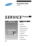
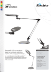
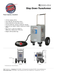
XENON TROUPER
Follow Spotlight
Type 48057
Issue 4/98
PRELIMINARY
STRONG
INTERNATIONAL
a division of Ballantyne of Omaha, Inc.
4350 McKinley Street
Omaha, Nebraska 68112 USA
Tel 402/453-4444 • Fax 402/453-7238
PREFACE
THE STRONG XENON TROUPER, Type 48057, is a direct current follow spotlight complete with a xenon lamphouse, power supply, optical system, base and yoke assembly, and color boomerang. It
utilizes proven design features of the Strong Xenon Super Trouper combined with advanced properties of the
Strong Super Trouper II. Using a 700 watt xenon bulb as a light source, the Xenon Trouper meets or exceeds
all professional requirements for short- to medium-throw follow spotlight applications.
ONLY THE SPECIAL XENON POWER SUPPLIES manufactured by Strong International
can be used with the xenon spotlight. For installation and operation of the power supply, see the manual
furnished separately.
THE XENON LAMPHOUSE utilizes a deep ellipse dichroic (“cold”) coated metal reflector
designed to operate in a fixed position with a horizontally mounted xenon bulb as the light source. The dichroic
reflector coating reduces heat at the aperture and optical system.
BULB ADAPTERS, required to mount the 700 watt bulb into the lamphouse, are included in
the spotlight accessory kit. Two anode adapters are supplied; the 65259 adapter, measuring 2-5/8 inches in
length, is used with the Hanovia XH0700HS bulb, and the shorter 65199 adapter is used with the OSRAM
XBO700W/HS OFR bulb.
ADJUSTMENT CONTROL for positioning the xenon bulb is located at the rear of the lamphouse. The adjustments are for the horizontal and vertical positioning, and focus control, of the bulb.
THE LAMPHOUSE INSTRUMENT PANEL is equipped with an ammeter and running time
meter. The ammeter indicates the operating current of the lamp, and the running time meter records the number
of hours the lamp has operated.
THE BULB is ignited and extinguished by use of the LAMP switch mounted on the instrument
panel. A DC Pulse Igniter Assembly requires no AC control circuit; it operates from DC open circuit voltage
normally generated by the xenon power supply. Remote ignition switching is accommodated by wiring a dry
contact across wires 3 & 6. See the Interconnection Wiring Diagram.
THE LAMP BLOWER, internally wired in the lamp, operates on 115 V.AC and is required to
keep the seals on the bulb at a safe operating temperature. This blower will operate continuously until power is
turned off at the main line switch to the xenon power supply.
THE LAMPHOUSE is supplied with a 13 foot cable containing the two DC leads, the ground
lead, and all AC control leads. The cable terminates in a multiple pin MS connector to mate to the receptacle on
the power supply.
WHEN TRANSPORTING the spotlight, it is recommended that the xenon bulb be removed
and placed in its original shipping carton with the cover on the bulb to insure against breakage.
XTR/001
LAMPHOUSE - POWER SUPPLY
Interconnection Diagram
LAMPHOUSE
(Connections Pre-wired)
MS CONNECTOR
Pin
Wire No,
A
DCB
DC+
C
2
D
3
E
4
F
5
G
6
I
7
J
8
M
Grnd
Remote - Auto
Sustained 5 Amp.
Dry Contact
(by Installer)
Lamphouse
Cable Assembly
Conduit
XENON
POWER
SUPPLY
SYSTEM MUST BE GROUNDED
All wiring must conform to local
codes; shield lamphouse cable in
conduit if required.
Grn
XTR/002
MS Connector (pre-wired)
DC+
DCGround Lug
(as req’d. for older units)
INSTALLATION & SET-UP
THE XENON TROUPER is shipped in sections which must be assembled. The Folding Base
Stand Assembly 65838 is shipped collapsed, and requires only unfolding and securing the (4) base legs using the
T-bolts supplied.
WHEN INSTALLED in a permanent location, the leveling feet must be removed, and the
clearance holes in the base leg brackets used for hardware (user supplied) to bolt the base to the floor or
platform. If it is desired to have the unit portable, when operating, the leveling feet must be adjusted down until
the weight of the spotlight has been shifted from the casters to the leveling feet.
THE INNER TUBE and support yoke has three holes to permit adjusting the height of the
spotlight. The three holes are on four inch centers and will allow an optical height of approximately 53 inches,
57 inches, and 61 inches above floor level to the optical center of the lamphouse and lens system. The leveling
feet may be adjusted through an additional two inch range. Insert the height location pin through the hole in the
outer tube and one of the holes in the inner tube.
THE HORIZONTAL SWING and vertical tilt locking knobs are on the right hand (operating)
side of the yoke assembly. Tighten both of these locking devices securely before attempting to place the lamphouse and lens system on the support yoke.
PLACE THE LAMPHOUSE and lens system on the yoke assembly, with the spot size control
handle to the right hand (operating) side, the same as the locking controls on the yoke. Line up the four
mounting holes in the bottom of the base rail with the four mating holes in the support yoke and secure with the
four 5/16-18 wing screws.
ATTACH THE COLOR BOOMERANG to the front of the optical system cover by inserting
the hinge pin through the hinge on the boomerang and optical system. Fasten the boomerang yoke to the slotted
angle bracket on the underside of the optical system pan. Adjust and securely tighten the wing nut and lock nuts
to hold the boomerang parallel with the front of the optical system housing.
ATTACH THE LAMPHOUSE CABLE CONNECTOR to the receptacle on the power supply.
Align the pins before tightening the locking ring. Do not energize the xenon power supply before first installing
the xenon bulb into the lamphouse.
EARLIER MODELS of Strong xenon spotlights included a heavy-gauge green ground wire in
the lamphouse cable assembly. This ground wire was attached to a ground stud connected to the power supply
cabinet. Current models of Strong power supplies include a 1/4-20 stud in the cabinet adjacent to the MS
connector to allow ground termination of older spotlights.
SAFETY PROCEDURES
READ CAREFULLY BEFORE INSTALLING XENON BULB
THE XENON BULB is highly pressurized. When ignited, the normal operating temperature
of the bulb increases the pressure to a level at which the bulb may explode if not handled in strict accordance to
the manufacturer’s operating instructions.
THE BULB is stable at room temperature, but may still explode if dropped or otherwise mishandled. Breakage resulting from transport and handling is not covered by the bulb manufacturer’s warrranty,
and it is strongly recommended to dismaount the xenon bulb when transporting the spotlight.
REFER bulb replacement and service to QUALIFIED PERSONNEL with adequate protective
clothing (face shield, clean cotton gloves, welder’s jacket). For routine lamphouse service, observe the following rules:
1.
Allow the bulb to cool to room temperature before opening the lamphouse. Put on protective clothing
described above.
2.
De-energize the xenon power supply at the AC source before opening the lamphouse compartment.
3.
When possible, encase the bulb in its protective cover when cleaning or servicing the lamphouse interior. The bulb, when outside the lamphouse, must be encased in the cover.
4.
Clean the bulb after it has cooled to room temperature. Do not touch the quartz envelope of the bulb;
fingerprints will burn in and create hot spots which may shorten bulb life. If fingermarks are made,
they should be carefully removed with methyl alcohol and cotton prior to bulb operation.
5.
Never view an ignited bulb directly. BLINDNESS OR PERMANENT EYE DAMAGE MAY BE
INCURRED.
6.
Use only xenon bulbs designated as OZONE FREE. When possible, vent the lamphouse exhaust to
outside atmosphere.
7.
Maintain the lamphouse blower in good operating condition. Keep the blower inlet clean for unrestricted air flow.
8.
To insure maximum bulb life, operate the lamphouse blower and the exhaust system for at least ten
minutes after extinguishing the bulb.
9.
If returning a bulb for warranty adjustment, pack it in its original shipping container. Complete and
return all required warranty information.
XG2/005
10.
Dispose of expired bulbs that are beyond warranty in the following manner: Wrap the bulb tightly in
several layers of canvas or heavy cloth. Place it on a hard surface and shatter the envelope with a sharp
hammer blow. DO NOT place an unshattered bulb in an ordinary refuse container.
11.
DO NOT PERMIT UNAUTHORIZED PERSONNEL TO PERFORM OR ATTEMPT ANY PHASE
OF XENON BULB HANDLING OR SERVICE.
Anode End Cap
Envelope
Anode Pin
Seal
Cathode End Cap
Seal
Cathode
Anode
Cathode Pin
700 WATT XENON BULB INSTALLATION
Type 48057 Trouper
CAUTION: OBSERVE ALL SAFETY PROCEDURES. Put on the protective face mask.
Wear clean cotton gloves to prevent marking the quartz envelope of the bulb with fingerprints.
REMOVE THE TOP COVER of the lamphouse by removing the four Holt head (tamperproof)
screws with the special screwdriver provided. Loosen the two knurled-head thumb screws (65152) on the front
bulb support yoke and pivot the retaining plate (65151) aside. Slide the 65131 clamp on the end of the igniter
lead over the brass socket of the rear bulb support collet (65844).
ASSEMBLE THE ADAPTERS to the 700 watt bulb prior to inserting the bulb into the lamphouse. Be very careful not to apply any strain on the quartz envelope when installing adapters. Screw the
cathode adapter (65198) onto the threaded negative stud so it seats firmly against the shoulder of the (-) end cap.
Slip the 65259 anode adapter over the positive pin up to the shoulder of the (+) end cap. Tighten the set screw
(00720) securely to insure a good electrical connection.
Thumb Screw 65152
Set Screw 00720
Hanovia XH0700HS
Retainer Plate 65151
Anode Clamp
65131
Anode Adapter 65259*
Clamping Screw 01532
Cathode Adapter 65198
Rear Bulb Support Collet 65960
* Use short adapter (65199) with OSRAM bulb
Front Bulb Support 65117
REMOVE THE PLASTIC PROTECTIVE COVER from the xenon bulb only if necessary.
Insert the bulb through the top of the lamphouse, between the reflector support and the front casting. Pass the
anode (+) end of the bulb through the hole in the reflector, taking care not to touch the surface of the reflector.
INSERT THE ANODE ADAPTER STEM into the rear support collet. The stem must be
inserted as far as possible to permit full focus travel of the bulb. Place the cathode adapter into the 65117 front
bulb support, pivot the retaining plate to its closed position, and tighten the (2) thumb screws. Tighten the
socket head clamping screw in the anode contact securely to insure a good electrical contact.
INSTALL THE CATHODE LEAD CONTACT over the end of the cathode adapter up to the
shoulder of the contact and tighten the clamping screw securely. Lay the lead in front of the air duct to minimize
the shadow.
A GLASS STRIP HEAT FILTER is supplied to reduce the thermal energy at the optical system and color gels. Insert the heat filter in the bracket provided on the inside of the lamphouse at the front
opening. Place the filter in position with the coated surface facing the bulb. The coated surface is indicated by
a small XX or other marking. This filter is a narrow strip that covers only the center portion of the beam. To
prevent damage to optical system components, do not operate the spotlight with the filter removed or reversed.
REMOVE THE PLASTIC COVER from the xenon bulb. Store the protective cover and the
original bulb packing in a secure location. The spare anode adapter (65199) is for use with an OSRAM 700
watt bulb (XBO700W/HS OFR) should such a bulb be used as a replacement.
SECURE THE LAMPHOUSE COVER with the (4) tamperproof screws using the special
screwdriver provided. The cover must be securely in position to actuate the interlock switch and permit lamp
ignition.
IT IS RECOMMENDED to establish a routine for periodically checking all electrical connections for tightness, particularly those at the bulb. A loose connection in the DC circuit will cause failure of the
contacts and leads, and may damage the bulb.
OPERATION
PLACE THE MODE SWITCH (on units so equipped) in the “MAN.” position and energize
the xenon power supply. The lamphouse blower will start and actuate the blower interlock switch to permit bulb
ignition. This lamp blower will operate continuously until the xenon power supply is de-energized.
PLACE THE LAMP SWITCH in the ON position and the xenon bulb will ignite. Allow a few
minutes for the current to stabilize, and read the lamphouse ammeter. The 700 watt xenon bulb must be
operated within the current range specified by the bulb manufacturer, normally 36 amperes nominal; maximum
current 40 amperes. Refer to the manufacturer’s documents shipped with the bulb for the exact figures.
ADJUST THE POWER SUPPLY as instructed in the power supply manual for the correct
operating current. New 700 watt bulbs are normally first operated at their nominal current level (36 A.). The
current setting must be increased in time to compensate for bulb aging, but do not, at any time, exceed the
maximum current rating (40 A.).
REMOVE THE REAR COVER PANEL (two pull type knobs) located below the instrument
panel. This will expose the bulb position adjustment controls.
THE CENTER SECTION of the control is a threaded member that focuses the bulb in relation
to the reflector. Turning this adjustment moves the bulb on the horizontal plane, into or out of the reflector.
Rotating this section clockwise moves the bulb away from the reflector. The small knurled screw to the left of
this section can be tightened to lock the focusing mechanism in place after the bulb alignment procedure has
been completed.
THE THUMB SCREWS to the left and right of the focusing control lock the horizontal and
vertical position of the bulb. These thumb screws are spring-loaded to apply a degree of friction against the
lamphouse back casting.
TWO METHODS are recommended to align the bulb in order to project the best light to the stage:
MOVE THE SPOT SIZE CONTROL HANDLE on the large lens carriage to the forwardmost
position to project the smallest spot possible with the iris, choppers, and dimming controls in their full open
positions. Project the spot to a wall or similar flat perpendicular surface opposite the spotlight.
TURN THE CENTER FOCUS CONTROL counterclockwise until a small black spot is projected on the wall. It may be well to run this adjustment both directions to permit positive identification of the
dark spot.
LOOSEN THE TWO THUMB SCREWS to the left and right of the focus control just enough
to permit manual movement of complete control assembly. Move the control assembly around the two thumb
screws and observe the smooth dark shadow of the bulb electrode inside the shaded circle of the reflector center
opening. The shadow of the electrode must be centered in the projected opening of the reflector.
MOVE THE CONTROL ASSEMBLY around the thumb screws until the dark electrode shadow
is as round as possible to project. It may be necessary to again rotate the focus control to define the electrode
shadow.
AFTER THE ELECTRODE SHADOW is as even around the outside as possible, tighten the
two thumb screws to lock this adjustment in place, and rotate the focus control to obtain the brightest light with
the best light distribution. Turn the spot focus control knob, located on the front of the lens mechanism, to
sharpen the edge of the spot.
THE SECOND METHOD of aligning the xenon bulb is to project the spot to the stage, and
using the bulb adjustment controls, obtain a “hot spot” in the projected spot. Center this “hot spot” in the
projected spot by moving the entire control section around the two thumb screws. Once the “hot spot” is
centered in the projected spot, lock the adjustment control in position with the two thumb screws and rotate the
focus control to obtain a spot with an even distribution of light. Turn the spot focus control knob at the front of
the lens mechanism to sharpen the edge of the spot.
THIS ADJUSTMENT should not be disturbed until the xenon bulb is rotated or replaced. At
this time it will be necessary to repeat the alignment procedure.
REPLACE THE REAR COVER PANEL over the bulb adjustment control mechanism.
Secure using the plastic fasteners.
BECAUSE OF MANUFACTURING TOLERANCES and normal bulb aging, it may be necessary to operate one lamp at slightly higher or lower current than others to obtain equal light balance between
two or more spotlights. These adjustments are made at the xenon power supply.
TO EXTINGUISH THE ARC, place the LAMP switch in the OFF position. The blower in the
lamphouse will continue running until the xenon power supply is de-energized. Allow the blower to operate and
cool the bulb for at least five minutes after extinguishing.
HANDLING THE SPOTLIGHT
GENERALLY THE BEST POSITION for the operator to stand is near the center of the spotlight, on the right hand side, although the angle of tilt and the size of the porthole may alter the position for the
most convenient operation.
EACH OPERATOR will, after a few minutes of operation, generally develop his own system
and position for operating the unit.
THE HORIZONTAL SWING LOCK LEVER and vertical tilt lock lever located on the base
assembly can be set to give the desired amount of friction on the spotlight swing to suit the individual operator.
THE LENS CARRIAGE FRICTION BRAKE is a nylon drag screw located on the outrider of
the large lens carriage, and is preset at the factory for most satisfactory operation. Individual requirements may
vary, and the brake can be adjusted to best suit the operator or allow for a severe “down” angle. Remove the
color boomerang and lens mechanism housing, loosen the nylon lock nut and adjust the screw on the friction
brake to apply the desired tension. Tighten the lock nut and replace the housing and boomerang.
REMOTE/AUTO OPERATION
TO IGNITE THE SPOTLIGHT from a remote location or an automation controller, the lamphouse must be equipped with the MODE (Auto-Man.) switch. With the MODE switch in the “AUTO” position,
and the LAMP switch “ON”, the lamphouse will ignite by means of a dry contact across terminals 3 and 6 at the
lamphouse or power supply (See Lamphouse-Power Supply Interconnection Diagram). This type of installation is intended for use only if the spotlight is locked down as a fixed spot without an operator at the unit.
EXHAUST SYSTEM INSTALLATION
IF THE SPOTLIGHT is installed in a closed booth, it is recommended to vent the lamphouse
exhaust to outside atmosphere to remove the heat from the booth.
THE EXHAUST STACK of the lamphouse is designed to fit a six inch diameter duct. The
exhaust system must be designed and installed is a way to eliminate any possibility of a down draft or of rain
dripping into the lamphouse. The exhaust fan must be capable of removing 750 lineal feet (150 cfm) of air per
minute at each lamphouse.
TO PERMIT MOVEMENT of the follow spotlight, install a section six inch diameter flexible
tubing between the lamphouse exhaust stack and the projection booth exhaust system. The two holes in the
stack exposed by removing the vent cap can be used to secure the tubing.
IF THE INSTALLATION is to be made in a location where it is not possible to install an
exhaust system, leave the vent cap mounted to the exhaust stack.
THE RADIATION from some xenon bulbs can convert the oxygen in the surrounding air to
ozone. In large quantities, ozone can endanger health, but it spontaneously changes back into oxygen in a very
short time, especially if it mixes with a large volume of air (as in an auditorium, arena, or outdoors). Most
currently manufactured xenon bulbs are classified as ozone free and do not release ozone.
OPERATION OF OPTICAL SYSTEM
THE IRIS CONTROL is the front lever which projects through the top of the optical system
housing. When this lever is to the left (as viewed from the rear of the unit), the largest aperture is provided.
Smaller apertures are obtained as the lever is moved to the right.
THE SPOT SIZE CONTROL HANDLE is located on the right hand side of the optical system
just above the base rail. A variation of spot sizes from full flood to small spot can be obtained by moving the
spot size control handle from one extreme to the other. Beam intensity is increased by this optical system when
reducing from flood to spot, and maximum intensity is reached when the spot size control handle is in the
extreme forward position.
THE MAXIMUM FLOOD SPOT is obtained with the iris control lever to the left (away from
operating side) for the largest aperture and with the spot size control handle moved as far to the rear as possible.
SMALLER SIZED SPOTS are projected as the spot size control handle is moved forward.
Most of the spot sizes needed will be produced with the iris in its maximum open position.
FOR A “HEAD SPOT,” or any spot smaller than can be obtained with the spot size control
handle in its extreme forward position, shift the iris control lever to the right (toward operating side) for a
smaller aperture. The iris control lever should always be returned to its extreme left position before the spot size
control handle is again moved to obtain larger spots.
THE MASKING SHUTTER (chopper) lever is the middle lever projecting through the top of
the optical system housing. The masking shutter blades are operated by this lever to shape the projected spot to
a rectangle, strip spot, or dousing.
THE DISENGAGED POSITION of the masking shutter lever is to the extreme right (toward
operating side) and varying degrees of masking to complete cutoff are obtained by moving the lever to the left
(away from operating side).
THE ANGLE of the masking shutter blades can be adjusted to compensate for the horizontal
projection angle. Remove the color boomerang and optical system housing, and loosen the screws holding each
of the masking shutter blades enough to allow adjustments. Ignite the bulb and adjust the angle of the bottom
blade by tapping with a screwdriver so its projected edge lies parallel to the footlights. Tighten the screw.
Operate the masking shutter lever to close the blades. Adjust the upper blade to close in line with the bottom
blade and tighten the screw.
THE FADEOUT MECHANISM AND DOUSER CONTROL is the rear lever projecting
through the top of the optical system cover. This lever controls the intensity of light from complete fadeout
when the lever is to the left, to full intensity when the lever is to the right.
THE SPOT FOCUSING CONTROL KNOB is located on the operating side of the optical
system at the forward end above the base rail. This control is used to adjust the optical system for the length of
throw. When making an adjustment, rotate the spot focusing control knob until the sharpest edge is obtained on
the projected spot.
OPERATION OF COLOR BOOMERANG
THE COLOR BOOMERANG is equipped with six color holders and an ultraviolet filter.
Additional filter holders can be supplied by an authorized Strong International Dealer.
TO OPERATE INDIVIDUAL COLOR FILTERS, lower the desired filter selector lever. A
rocker catch located in the color disc housing holds the filter in position.
TO RELEASE A COLOR, push the filter release lever or engage another color, thus releasing
the previous color automatically.
TO REPLACE A FILTER HOLDER, open the hinged top of the color disc housing and lift out
the desired filter holder.
HIGH TEMPERATURE FILTERS (RoscoLux® or equivalent) cut to nine inch diameter are
required, and are secured in the filter holders with paper fasteners.
NOTE: WHEN PLACING COLOR FILTERS in the boomerang, the less dense colors (pink,
amber) should be placed in the holders toward the rear of the boomerang (toward arc), and those of greater
density (red, green) should be placed in the holders toward the front of the boomerang (away from the arc).
COLOR TEMPERATURE REDUCTION FILTERS, required for use with television and
videotape, are available from theatrical supply dealers.
MAINTENANCE
THE STRONG XENON TROUPER SPOTLIGHT requires very little maintenance to keep it
in good working order.
THE REFLECTOR should be cleaned periodically with a soft, clean, lint-free cloth to remove
dust from the reflecting surface. If excessively soiled, the reflector may be cleaned with Windex® or an equivalent glass cleaner. DO NOT use abrasive cleaners of any kind. Clean the heat filter glass; replace with the
coated surface toward the lamphouse.
CHECK ALL ELECTRICAL CONNECTIONS for tightness on a regular basis. Loose connections, particularly in the DC circuit, may cause premature bulb failure and damage lamphouse components.
THE XENON BULB should be checked occasionally for the presence of dust or foreign materials. If necessary, clean the quartz envelope of the bulb with alcohol, and wipe dry with a clean, lint-free cloth.
Observe all safety procedures when working with the exposed bulb.
THE INSIDE OF THE LAMPHOUSE and the blower should be cleaned periodically, depending on the dust conditions at each installation. Keep the blower inlet grille clean to permit free air flow. The
blower is permanently lubricated and requires no oil.
THE LENS SYSTEM should be kept clean to prevent any light reduction in the projected spot.
Tighten the horizontal swing and vertical tilt locking clamps. Remove the boomerang and the optical system
cover to reach and clean the back surface of the large lens. Remove the cover casting over the fadeout, chopper,
and iris controls to remove the small projection lens which is held in place with a large spring-type retainer ring
at the front of the lens barrel.
CLEAN THE PROJECTION LENS and large lens with with any cleaner approved for use on
coated projection lenses. Replace the projection lens with the end with the FL marking ring toward the iris;
secure with the retainer ring.
BEFORE TRANSPORTING the spotlight, remove the xenon bulb from the lamphouse. Place
the bulb in its plastic cover and original shipping container.
LAMPHOUSE WIRING DIAGRAM
Xenon Trouper
A = BLK DCB = RED DC+
C = BRN #2
D = PINK #3
E = ORN #4
F = BLU #5
G = YEL #6
I = GRY #7
J = BLK #8
M = GRN Gnd
Wires 7 & 8 not connected to Trouper
MS CONNECTOR
PARTS LIST
Wiring Diagram
Ref,
Desig.
B1
C1,2
C3
C4A,B
C5
DS1
M1
M2
R1
S1
S2
S3
S5
J1
Part No.
62-98002
76132
76133
80177
81947
65891
39195
65142
82167
80168
81275
81276
80168
37990
Description
Blower, 115 V.AC, 50/60 Hz.
Capacitor, .005 µf, 600 WVDC
Capacitor, .01 µf, 400 WVDC
Capacitor, 1.0+1.0 µf, 600 WVDC
Capacitor, .01 µf, 600 WVDC
Xenon Bulb, 700 Watt
Elapsed Time Meter, 60 Hz.
Elapsed Time Meter, 50 Hz. (Export)
Ammeter, 0-150 A.
Shunt, 150 A. 50 mV.
Top Cover Interlock Switch
LAMP Switch, ON-OFF
MODE Switch, AUTO-MAN.
Side Cover Interlock Switch
Fan Cord & Plug Assembly
65503
65935
88318
DC Pulse Igniter Assembly
Lamphouse/Power Supply Cable Assembly
MS Connector (incl. with 65935)
TROUBLE CHART
NORMAL OPERATION
WHEN THE SWITCH in the main AC supply line to the xenon power supply is in the ON
position, and the 30 A. circuit breaker on the switching power supply is ON, the POWER light on the xenon
power supply will glow. The lamphouse blower will start. The blower in the power supply, if a older Strong
high reactance type (61000, 61001) or current production switching type, will operate.
IF THE LAMPHOUSE TOP COVER and access panel are correctly installed, the top and side
panel interlock switches will close. At this time, the control circuit to the LAMP switch will be completed.
THE MODE SWITCH, located on the lamphouse instrument panel, should be in the “MAN.”
(manual) position. This is the normal setting for spotlight opertion, as it allows direct ignition control by the
operator.
WHEN THE “LAMP” SWITCH is placed in the ON position, the AC control circuit in the
lamphouse will energize the power supply contactor circuit and provide DC current to the igniter and bulb. The
high DC open circuit voltage generated upon start-up of the power supply will actuate the DC Pulse Igniter.
THERE WILL BE a distinctly audible high voltage arc ping at the igniter arc gap and across
the bulb electrodes. The bulb should ignite immediately after one or two of these high voltage pulses, and the
lamp current will adjust to the output setting of the xenon power supply. Multiple ignition pulses prior to bulb
ignition normally indicate a low DC output setting. See xenon power supply manual. A “warm” or aged xenon
bulb might also require multiple strikes.
TROUBLE SHOOTING
IF THE XENON BULB does not ignite, observe the following operational sequences for assistance in locating and isolating the trouble area.
WHEN THE FAN(S) and the indicator light on the power supply are on, the AC circuit in the
power supply is trouble free up to the terminal block in the power supply.
AT THIS TIME, the lamphouse blower should operate. If this does not occur, the trouble is in
the cover interlock switch, the access panel interlock switch, the blower motor, a loose connection, or a broken
#2 or #4 lead. Check at this time for 115 V.AC Control Voltage at the cover interlock switch (wires 2 & 4), the
side access panel (wires 13 & 14), and the blower terminals (9 & 12). The cover interlock switch must be
manually actuated to energize the blower. Observe caution when taking voltage readings in a power ON
condition.
THE VANE on the air flow switch should actuate. With the MODE switch in the “MAN.”
position and the LAMP switch in the “ON” position, the running time meter should start and indicate elapsed
time. If this meter does not operate, check for continuity at the MODE and LAMP switches. A defective
running time meter will not prevent bulb ignition.
WITH THE “LAMP” SWITCH in the “ON” position, a distinct high voltage arc ping should
be heard at the spark gap in the igniter, and the flash of the xenon bulb should be visible through the ammeter as
a high RF voltage pulse is applied across the bulb electrodes.
IF THE HIGH VOLTAGE PING or the flash at the ammeter is not apparent, check the “No
Load” DC Voltage between the lamphouse and power supply. Check the DC voltage across terminals #10 (-)
and #15 (+). A reading of 85-150 V.DC should be measured if using a high reactance power supply; 140-170
V.DC if using a switching type. If this voltage is not indicated, the problem is in the leads between the lamphouse and power supply, or in the power supply boost circuit. See the trouble shooting section of the power
supply manual for additional instructions.
THE SWITCHING-TYPE xenon power supply normally furnished with the spotlight system
contains thermal overload switches and circuits to protect the power supply from high or low AC input voltage.
A lack of open circuit voltage, or interruptions in sustaining DC current, may be traced to these circuits.
IF THE HIGH VOLTAGE ARC is audible at the lamphouse and the bulb does not flash, check
for a lamphouse DC lead arcing to ground. If no ground fault is detected, replace the bulb and attempt ignition
with the new bulb.
IF THE HIGH VOLTAGE ARC is audible at the lamphouse, the flash of the bulb is visible in
the ammeter, but ignition of the bulb is not sustained, the problem area is in the power supply. See the trouble
shooting section of the power supply manual for additional instructions.
IF THE HIGH VOLTAGE ARC is not audible or the flash of the bulb visible, the problem is in
the igniter assembly.
EXCHANGE of components (i.e. igniters, power supplies) between similar Strong Xenon
Troupers to aid in diagnosis of a problem is encouraged. This will not lead to equipment damage, and will not
void equipment warranty.
XENON TROUPER TROUBLESHOOTING
Bulb fails to ignite.
1. MODE switch S3 set to “AUTO.” Place in “MAN.” position when not employing automated or remote
lamphouse operation.
2. AC power not on to lamphouse. Turn switching power supply 30 A. circuit breaker ON. If 115 V.AC not
read at 2 & 4, see power supply manual.
3. Top cover or side access panel interlock switch (S1, S5) open. Close and secure lamphouse top cover.
Tighten all four mounting screws; check switch actuating screw. Tighten side access panel screws.
4. Faulty interlock switch(s). Check for 115 V.AC at 9 & 12; replace switch(s) if defective.
5. Faulty S2 “ON-OFF” switch. Check for voltage at 3 & 5; check for loose terminals or wiring. Replace if
defective.
Bulb fails to ignite; ping audible, bulb flash visible.
1. Inadequate DC output from xenon power supply. Set power supply output to correct range required for
bulb wattage (65 A. for 1.6 kW, 75 A. for 2 kW).
2. If bulb flash is visible but faint, check for defective glass capacitor 65216 in igniter (capacitor body
cracked or leaking oil). Replace if defective.
3. Faulty or expired xenon bulb. Replace as required.
Bulb fails to ignite; ping audible, no bulb flash.
1. Faulty xenon bulb. Check for cracked electrodes or darkened envelope. Replace if defective.
2. Ignition pulse shorting to ground. Inspect DC leads for burned insulation; dress leads away from grounded
metal components.
No high voltage ping audible; MODE switch in “MAN.” and LAMP switch in “ON.”
1. Loss of AC control voltage. Check xenon power supply for tripped circuit breaker or open thermal switch.
See power supply manual.
2. Little or no DC “No Load” voltage. Measure DC “No Load” voltage at 10 & 15. See power supply
manual.
3. Open fuse F1 (600 V.) on switching power supply. SEE POWER SUPPLY MANUAL. Allow (20)
minutes for capacitor discharge before replacing.
4. Faulty igniter. Check for adequate DC “No Load” at 10 & 15. If present, and igniter does not fire, replace
igniter.
Bulb goes out during operation.
1. Xenon power supply overheated; thermal switch open. Check power supply blower(s), air inlets and
outlets unobstructed. See power supply manual.
Bulb goes out during operation (continued)
2. Xenon bulb depressurizing. Check for envelope discoloration; replace if defective.
3. Power supply brown-out protection actuated by voltage drop. See power supply manual.
4. Phase loss detected by power supply (3 phase units only). See power supply manual.
Power supply does not energize when actuated.
1. S1 or S5 cover interlock switch, S4 air vane switch, S2 power switch, S3 MODE switch. Check for 115
V.AC at each station; replace defective component.
SEE POWER SUPPLY TROUBLESHOOTING UNDER SAME HEADING.
Noise in theatre sound as bulb ignites.
1. Faulty RF suppression capacitor(s). Remove and test C1, C2, C3, C4A or C4B. Replace if defective.
2. Lamphouse, power supply, or sound system not properly grounded. Connect to adequate earth ground.
3. Leads between lamphouse and automation contact not shielded. Shield leads in conduit.
Excessive light flicker.
1. Faulty or aged bulb. Check for cracked or sagging electrodes; replace if defective.
2. Excessive ripple in DC output. See power supply manual.
3. Arc stabilization magnet reversed. NORTH pole should point toward operator side. Check with compass
if required.
Reduced light output.
1. Normal bulb aging. Increase output current. DO NOT EXCEED MAXIMUM CURRENT SPECIFIED
BY BULB MANUFACTURER.
2. Soiled reflector. Clean using commercial glass cleaner. USE NO ABRASIVES.
3. Soiled heat filter, projection lens or large lens. Clean as required.
Extremely long duration between ignition pulses.
1. Low DC “No Load” from xenon power supply. Check “No Load” voltage; see power supply manual.
2. Defective spark gap. A “Ping” sound is normal; excessive “Hissing” is abnormal. Replace if defective.
3. Low AC voltage to lamphouse. Check for 115 V.AC at 2 & 4; if below 95 volts, check stepdown or
isolation transformer in xenon power supply. See power supply manual.
Color gels burning or fading prematurely.
1. Bulb focused to “hot spot.” Refocus bulb to flat field with iris fully open and spot size control handle
(“trombone”) fully forward.
2. Heat filter glass reversed or peeled. Check for coated surface toward bulb; replace if coating peeled.
3. Reflector coating peeled. Replace if defective.
15
16
17
18
20
19
21
22
14
13
23
1
2
12
3
11
4
FIGURE 1
9
10
8
7
6
5
PARTS LIST
Figure 1
Item
1
2
3
4
5
6
7
8
9
10
11
12
13
14
15
16
17
18
19
20
21
22
23
Part No.
65114
00805
65164
65111
65865
65155
65156
65117
65151
65152A
01567
65115
00262
65171
65175
41-51122
00876
00805
01432
65503
80168
72178
65112
61-98002
65966
65827
65960
21-48027
65131
65134
00182
65160
00255
80168
65185
00254
23756
Description
Reflector Bulkhead Casting
Tie Rod Lock Nut, 1/4-20 Hex
Tie Rod, Bulkhead to Front Casting
Lamphouse Front Casting
Lamphouse Base Pan & Lower Side
Inner Heat Shield, Left
Inner Heat Shield, Right (not shown)
Front Bulb Support Yoke
Retainer Plate
Thumb Screw, Retainer Plate (2 req’d.)
Mounting Screw, 10-24 x 1/2" Bind Head
Air Duct Casting
Screw, 8-32 x 1" Fillister Head
Insulator Bushing
Insulator Plate
Screw, 1/4-20 x 3/4" Hex Head
Lockwasher, 1/4" Split Ring
Hexnut, 1/4-20
Screw, 1/4-20 x 1/2" Socket Head
DC Pulse Igniter Assembly
Side Cover Interlock Switch (S5)
Switch Mounting Bracket
Lamphouse Back Casting
Blower (B1), 115 V.AC, 50/60 Hz.
Igniter Lead & Clamp Assembly
Bulb Positioning Assembly (less Collet)
Rear Support Collet
Collet Retaining Ring
Contact Clamp (incl. with Item 17)
Barrier Strip, (10) Terminal
Screw, 6-32 x 7/16" Fillister Head
Barrier Strip Mounting Bracket
Screw, 8-32 x 5/16" Fillister Head
Top Cover Interlock Switch (S1)
Switch Mounting Bracket
Screw, 8-32 x 1/4" Fillister Head
Flanged Reflector, 10" Dichroic
NOT SHOWN
65895
65866
01736-1
65149A
Lamphouse Top Cover Assembly
Cap, Exhaust Stack
Tamperproof Screw, 10-32 x 1/2" Holt Head
Screwdriver (for 1736-1)
FIGURE 2
PARTS LIST
Figure 2
Item
1
2
3
4
5
6
7
8
9
10
11
12
Part No.
65142
81276
81275
65116
65197
37985
15010
65150
65112
65959
65153
65154
76329
65891
65870
00953
01343
01620
01382
65107
Description
Ammeter (M2)
MODE Switch (S3), AUTO-MAN.
LAMP Switch (S2), ON-OFF
Casting, Bulb Positioning Control
Fender Washer, Inner
Thumb Screw
Compression Spring
Fender Washer. Outer
Lamphouse Back Casting
Focus Screw & Bearing
Focus Lock Screw
Nylon Ball, 3/16" Diameter
Plug Button, Chromed
Elapsed Time Meter (M1), 60 Hz.
Elapsed Time Meter, 50 Hz. (Export)
Screw, 4-40 x 1/2" Round Head
Lockwasher, #4
Hexnut, 4-40 Brass
Screw, 8-32 x 3/16" Bind Head
Instrument Panel (less Components)
FIGURE 3
PARTS LIST
Figure 3
Item
1
2
3
4
5
6
7
8
9
10
11
12
13
14
-
Part No.
80168
01741
65185
00254
00891A
65876
79131
65960
21-48027
M4361
00377
82167
00385
00875
65935
95119
95120
81947
00381
80177
00375
00885
65966
00685
00876
65131
01532
65951
65134
00182
65160
00255
00891A
65890
00182
Description
Top Cover Interlock Switch (S1)
Lockwasher, 7/16"
Switch Mounting Bracket
Screw, 8-32 x 1/4" Fillister Head
Lockwasher, #8
Potentiometer (early models*)
Ground Terminal
Rear Bulb Support Collet
Collet Retaining Ring
Cable Clamp
Screw, 10-24 x 1/4" Fillister Head
Shunt (R1)
Screw, 10-24 x 1/2" Fillister Head
Split Lockwasher, #10
Lamphouse/Power Supply Cable Assembly
Bushing, 1-1/4"
Lock Nut, 1-1/4"
Capacitor (C5)
Ground Screw, 10-24 x 5/8" Fillister Head
Capacitor (C4A, C4B)
Screw, 10-24 x 3/16" Fillister Head
Lockwasher, #10
Igniter Lead & Clamp Assembly
Screw, 1/4-20 x 3/8" Hex Head
Split Lockwasher, 1/4"
Contact Clamp (incl. with Item 10)
Clamping Screw, 8-32 x 7/8" Socket Head
Lamphouse Wire Harness Assembly
Barrier Strip, (10) Terminal
Screw, 6-32 x 7/16" Fillister Head
Barrier Strip Mointing Bracket
Screw, 8-32 x 5/16" Fillister Head
Lockwasher, #8
Capacitor Assembly (C1, C2, C3)
Screw, 6-32 x 7/16" Fillister Head
Items 20 & 21 shown offset for clarity. See Figure 5, Items 11-13.
Small Lens not shown;
see Parts List, Item 23
FIGURE 4
PARTS LIST
Figure 4
Item
1
2
3
4
5
6
7
8
9
10
11
12
13
14
15
16
17
18
19
20
21
22
23
-
Part No.
51875
51493
51492
00217
00830
00866
51102
51133
51489
00866
01475
41-51170
51168
51167
00490
51114
51992
51509
48410
01752
01754
48899
51162
41-51178
51114
51485
48127
48147
51157
51160
00830
48895
01307
00541
48896
51101
48404
48042
00241
Description
Carriage Casting, Large Lens
Lens Retaining Ring
Rubber Lens Cushion
Screw, 8-32 x 5/16" Round Head
Flatwasher, #8 Brass
Flatwasher, #10
Large Lens
Lens Focus Block
Lens Focus Shaft
Flatwasher, #10
Cotter Pin, 1/16" x 3/8"
Set Screw, Focus Knob
Focus Knob, Lens Mechanism
Post, Focus Ribbon
Mounting Screw, 1/4-20 x 1/2" Flat Head
Stop Collar
Lens Focus Ribbon
Handle, Red Plastic
Handle Shaft
Lock Nut, 1/4-20 Nylon Hex
Friction Brake Screw, 1/4-20 x 1" Hex Head Nylon
Base Pan, Welded Assembly
Tension Spring
Set Screw, 10-32 x 1/4"
Stop Collar
Slide Rod (Left & Right)
Truarc Ring, #5100-56
Truarc Ring, #5101-56
Pulley, Focus Ribbon
Pulley Stud
Flatwasher, #8 Brass
Lens Housing Welded Assembly
Screw, 10-32 x 3/8" Pan Head
Screw, 1/4-20 x 1/2" Pan Head
Small Lens Carriage Welded Assembly
Small Lens (not shown; mounts to 48896)
Small Lens Mounting Plate (not shown; 2 req’d.)
Mounting Tube (for Item 24 Lens)
Tube Mounting Screw, 8-32 x 5/8" Flat Head
PARTS LIST, Figure 4 (continued)
Item
24
25
26
-
Part No.
44239A
83155
51160
00830
Description
Projection Lens
Retaining Clip, Projection Lens
Pulley Stud
Flatwasher, #8 Brass
NOT SHOWN
48891
49342
01346
00877
Base Rail, Lamphouse & Lens Mechanism
Hand Rail
Screw, 5/16-18 x 1/2" Hex Head
Split Lockwasher, 5/16"
FIGURE 5
PARTS LIST
Figure 5
Item
1
2
3
4
5
6
7
8
9
10
11
12
13
14
15
16
17
18
19
20
21
22
23
24
25
26
27
28
29
30
31
32
33
34
35
36
37
38
39
Part No.
Description
10048A
Knob, Red Plastic
48402
Iris Shaft
00179
Screw, 6-32 x 1/4" Fillister Head
00892
Lockwasher, #6
51978
Friction Spring & Pad (for 51979)
00184
Screw, 6-32 x 5/8" Fillister Head
00892
Lockwasher, #6
51979
Iris (as shown; also see Figure 5A)
See Figure 5A for current configuration
51226
Stud, Chopper Blade
51871
Aperture Support Plate, Welded Assembly
51160
Pulley Stud
51157
Small Pulley
00830
Flatwasher, #8 Brass
47191
Chopper Blade
47191
Chopper Blade
47982
Slide Assembly, Chopper Blade
00253
Screw, 8-32 x 3/16" Fillister Head
00891A
Lockwasher, #8
00853
Washer, 1/4" Steel, S.A.E.
51156
Friction Plate
51602
Pull Rod, Lower Fadeout Blade
00876
Split Lockwasher, 1/4"
00805
Hexnut, 1/4-20
51517
Spacer
00866
Flatwasher, #10
00400
Screw, 10-32 x 1-1/2" Fillister Head
00831
Flatwasher, #10; .036" Thick
01344
Lockwasher, #10
00378
Screw, 10-32 x 1/4" Fillister Head
51443
Pivot Shaft Retainer
51226
Stud, Chopper Blade
48898
Fadeout Mechanism Bracket, Welded Assembly
48878
Lower Fadeout Blade
48879
Upper Fadeout Blade
51153
Pivot Bushing
51515
Pull Rod, Upper Fadeout Blade
00919
Cotter Pin, 1/16" x 1/2"
51520
Fadeout Control Handle Bracket
51452
Handle, Fadeout Control
01406
Nut, 5-16-18 FlexLock Hex
PARTS LIST, Figure 5 (continued)
Item
40
41
42
43
44
45
46
47
48
49
50
51
52
53
Part No.
00853
51156
51498
51155
10048A
00254
00891
47170
48406
51153
00876
00805
01406
51497
Description
Washer, 1/4" Steel, S.A.E.
Friction Plate
Chopper Pull Rod, Short
Handle, Chopper Control
Knob, Red Plastic
Screw, 8-32 x 1/4" Fillister Head
Lockwasher, #8
Iris Stop Bracket
Bracket, Chopper Control Handle
Pivot Bushing
Split Lockwasher, 1/4"
Hexnut, 1/4-20
Locknut, 5/16-18
Chopper Pull Rod, Long
FIGURE 5A
Part No.
01306
21-70029
24369
24372
24374
25034
25035
41-51252
41-50325
41-51530
48402
Description
Screw, 6-32 x 5/16"
Spring Washer
Bell Crank
Adapter Ring
Iris
Iris Clamp
Link with Pins
Screw, 8-32 x 5/8"
Screw, 6-32 x 3/8"
Shoulder Bolt
Iris Control Handle
48402
01306
24369
24374
21-70029
41-51530
41-51325
25035
41-51252
25034
24372
51850 BOOMERANG ASSEMBLY
BOOMERANG PARTS LIST
Part No.
51850
00180
00255
00793
00829
00831
00837
00839
00856
00886
01309
01310
01406
01419
01456
01515
01566
01573
45209
49226*
51166
51192
51196
51347*
51376
51396
51398
51399
51406
51522
51526
51527
51530
51535
51591
51842
51845
51848
51928
51932
51933
51934
90473
91199
Description
Boomerang Assembly
Screw, 6-32 x 5/16" Fillister Head
Screw, 8-32 x 5/16" Fillister Head
Nut, 6-32, Steel
Washer, #8 Brass, 3/8" O.D.
Washer, #10 Brass, 7/16" O.D.
Washer, 5/16" Brass, 3/4" O.D.
Washer, 3/8" Brass, 7/8" O.D.
Washer, 1/2" S.A.E.
Lockwasher, #8 Split Ring
Order 41-35065 Wing Nut 1/2-13
Hex Half Nut, 1/2-13
Locknut, 5/16-18 x 1/4"
Screw, 5/16-18 x 3/4" Hex Head Cap
Paper Fastener
Screw, 4-40 x 1/4" Round Head
Screw, 10-24 x 5/16" Pan Head
Jam Nut, 1/4-20
“E” Ring, 3/16"
Adjusting Screw (Replace with 51347*)
Shoulder Screw
Ultra Violet Filter
Hinge Pin
Adjusting Screw (Mfr. 1991 and Later)
Cover Plate, Color Frame
Catch
Nylon Spacer Washer
Spacer
Clip, U.V. Filter
Frame, Color Disc Housing
Shaft, Rocker Catch Pivot
Shaft, Color Disc Pivot
Yoke
Screw, U.V. Filter Pivot
Latch, Color Disc Housing
U.V. Filter Support Frame Assembly
Rocker Catch Assembly
Housing, Welded Assembly
Color Frame Slide Channel Assembly
Arm Assembly (5-3/16")
Arm Assembly (4-11/16")
Arm Assembly (4-3/16")
Spring
“E” Ring, 5/16"
1
2
3
33
4
5
32
31
6
30
7
8
9
29
28
27
26
25
24
23
10
11
12
13
22
14
21
17
19
16
20
18
15
FOLDING BASE & STAND
Assembly No. 65838
PARTS LIST
Folding Base & Stand
Item
1
2
3
4
5
6
7
8
9
10
11
12
13
14
15
16
17
18
19
20
21
22
23
24
25
26
27
28
29
30
31
32
33
Part No.
49120
02411
49121
41-35020
00845
49126
49125
49124
49129
49130
10048A
49179
49114
10048A
83742
49208
00854
41-51397
41-70007
41-35056
83745
83744
49226
00919
48395
65824
48399
83381
00687
01304
48394
65431
01317
65823
00689
83341
48884
Description
Tilt Axis Bolt
Washer, 1.25" O.D. x .640" I.D.
Washer, Tilt Axis
Hexnut, 3/8-16
Flatwasher, 3/8" S.A.E.
Clamping Plate
Clamping Spring, Compression
Clamp Bushing
Shaft, Tilt Clamp
Handle, Clamp Shaft
Knob, Red Plastic
Swivel Clamping Nut
Handle Stud, Swivel Clamp
Knob, Red Plastic
Base Column, Welded Assembly
Swivel Caster
Flatwasher, 3/8" S.A.E.
Screw, 7/16-14 x 3" Hex Head
Flatwasher, 7/16"
Nut, 7/16-14 FlexLock
Leg T-Bolt, Welded Assembly
Base Leg, Welded Assembly
Leveling Foot
Lock Nut, 1/2-13 Hex
Height Adjust Pin, 3/8" Diameter
Inner Tube & Ring Welded Assembly
Bronze Washer
Collar, Swivel Clamp
Screw, 1/4-20 x 1/2" Hex Head
Screw, 8-32 x 5/16" Pan Head
Yoke Cover Plate
Inner Tube Retaining Collar
Screw, 1/2-13 x 2-1/2" Hex Head
Yoke, Welded Assembly
Screw, 1/4-20 x 5/8" Hex Head
Cable Clamp
Saddle & Quadrant Plate, Welded Assembly
ASSEMBLIES
65838
18765
Base & Stand, Complete (Items 1-33)
Folding Base Assembly (Items 14-20)