1
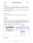
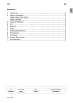
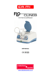
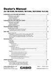
CDA
SPRAYER
Instruction Manual
USER GUIDE PROTOCOL
CDA SPRAYER C/W FLOAT,
10L TANK AND BATTERY CASE.
ABOUT CDA SPRAYER
An electric sprayer that allows the fulfillment of optimal treatments with capacity of 10
litres.
This sprayer is manufactured in durable and impact resistant material. It is chemical
resistant an UV stabilized.
The sprayer has been designed using the very latest technology to give longevity and
reliability.
The battery is rechargeable 6 volt 3 Ah S.L.A unit (Sealed Lead-Acid).
The power requirement of the motor is only 0.10A.
The charger is able to complete battery recharge in 8 hrs.
Test has shown that the drop in voltage and current is insignificant to cause he drop in
motor speed even after continuous use of over, as such giving a consistent spray
distribution.
Benefits:
Reduction of waste.
Improved safety for the operator.
Reduction of the environmental risks.
Chemical saving.
Reduction of spraying time.
Reduction of application costs.
AN EFFECTIVE PRODUCT IS NOT ENOUGH.
THE PRODUCT ITSELF MUST BE CORRECTLY APPLIED.
1
PROTECTIVE CLOTHING
When applying herbicides with the CDA sprayer the following items MUST be worn:• Rubber gloves and boots
• Long Sleeve shirt.
• Long Trousers.
• Eye goggles.
It is also recommended to wear:• Disposable coverall OR an apron.
PREPARING FOR SPRAYING
The sprayer is delivered in a collapsed form. To assemble ready for spraying:
1
1) Extend the sprayer and securely connect the feed tube 1 to the flow valve.
2) Connect the male 3 pole connector 2 from the lance to the tank female 3 pole
connector 5 and lock the both connector.
3) Remove the atomiser protective cover 4 and check by hand that the atomiser
disc spins freely.
4)Turn on the switch 3 .
2
STEP-BY STEP FAULT FINDING PROCEDURE
Motor Not Functioning
1) Battery terminal is not inline with the sprayer's terminal.
2) Faulty battery or carbon formed on the terminals.
3) Loose connection of battery or switch terminal.
4) System short circuit.
5) Electric motor of the pump has decayed.
6) Charging was done correctly.
Switch 3 should be in ON position when charging, 3 pole connector is
connected properly.
Motor Functioning But Not Spraying As Desired
1) Nozzle is blocked.
2) Disc is blocked.
3) Hose is blocked.(Rane cases)
4) Motor has worn out.
Tank Is Leaking At The Side
1) Valve (STMC-021-10045) is broken.
2) Washer (STTK-012-10019) has worn out or missing.
3) Hose clip is loose or broken.
METHODS OF USE
For more detailed information on preparation and use of sprayers refer to the
manual supplied with the CDA sprayer.
Pre-mix the herbicide product in the required volume of water in the 10 litre
backpack (see section below on mixing and calibration) and attach the backpack to
the sprayer.
Hold the sprayer at an angle of between 30° - 40° to the ground with the atomiser
head positioned about 20cm above the weed. Soil age or soil surface. In this
position the atomiser head should be angle slightly forward to spray away from
operator. N.B. make sure the spray head is more that 60cm away from the operator
avoid contamination.
3
MAINTENANCE AFTER USAGE
The sprayer must be decontaminated inside and out with mild solution of detergent,
followed by complete FLUSHING with clean water and run pump to clean the
systems as well.
• Do not attempt to
h into base compartment and hand lance, if necessary
just wipe them with a DAMP CLOTH.
• Remove nozzle and
s for individual cleaning.
• Store separately if the sprayer is not going to be used for several days.
• Nozzle need to be replaced every 6 months based on usage and
replaced when necessary.
s to be
RECHARGING THE BATTERY
1
i. Connect the battery charger male 6 3-pole connector to the tank female 3-pole
connector 5 and lock the both connectors.
ii. The tank’s switch 3 should be in ON position.
iii. Connect the battery charger plug to the main electric power and switch on. The Red
static ‘in charging’ and the green static ‘done charging’ indicator will glow. The
battery will need to recharge for 8 hours.
iv. After done with charging, remove the battery charger 6 from the main electric
power and disconnect the 3-pole connector.
PROLONGED INACTIVITY
• If the CDA sprayer will not be use for a long time remove the battery and store it
in a cool and dry place.
• Recharge battery every 3 months.
4
GENERAL PRECAUTIONS
• Do not switch the sprayer on with disc cover not removed, this may damage the
serrated disc.
r in order to avoid blockage of the nozzles.
• Fill the tank only through the tank
(Avoid spillage)
• NEVER USE CLASS ONE PRODUCTS WITH CDA SPRAYERS.
• Use only clean water without impurities.
• Do not start spraying without
g the tank cap
y.
• Distribute the chemical evenly, keeping the nozzle at an adequate distance from
the surface to be treated.
INSTRUCTION BEFORE USAGE
• Make sure that GREEN DIODE lights up with static (this occurs when the battery
is fully charged and switched to trickle charge).
• Check the FILTER and NOZZLE to make sure it is free from any blockage or
sediments.
• Make sure that all FILTERS, O-RING and NOZZLE is in place correctly and
su ciently tight to avoid leakage.
• Always pour liquid into the tank through tank
backrest.
r and avoid spillage on
• Make sure tank cap is close properly.
• Adjust straps to suit individual sprayer operators.
• Wipe o any spillage on the tank surface.
IN FIELD USAGE
• Never drag the sprayer on the ground or on weeds while transporting and when
reloading the liquid.
• Avoid the disc hitting the ground or weeds while spraying, this could also cause
blockage to the nozzle and disc.
• An adequate distance to be kept from the surface to be treated.(20cm)
5
* Switch on the atomiser disc and then open the w tap. Liquid should be seen
g down the hose pipe to the atomiser head.
* With the lance held preferably to the side of the operator walk at a moderate pace
(around 54 meters in one minute). This will treat a 1.2m wide strip and will cover
an area of 65 meter square each minute.
* When spraying has
d close the w tap and then switch o the atomiser.
Raise the spray head up to an angle of 45 ° (with the spray head uppermost) and
then open the tap w valve to allow any remaining liquid in the hose pipe to
back to the tank. Close the tap w valve.
* For ease of transport the tank can be disconnected (use the flow valve to isolate any
liquid left in a backpack) and the sprayer collapsed (OFF the switch and disconnect the
3 pole connector).
MIXING AND CALIBRATION
With the CDA sprayer, herbicides are usually applied in around 25 litres of water per
hectare.
To prepare the spray mix, select the rate of product to be applied per hectare then
add su cient water to make up to the total application volume required.
E x a m ple :
Glyphosate rate
f o r o n e h e c ta r e
-
3 litres
Add water
-
Total volume
-
+
7 litres
10 litres
Note:
When applying herbicide products ALWAYS follow the label recommendations.
The following table can be used to select the correct feed nozzle:
Appendix 1
Total Spray
Volume
Swath Width
(M)
Feed
Nozzle
25
1.2
3
Flow Rate
(ml / min)
Walking Speed
(m / sec)
166
0.9
* Some products when mixed in water can be slightly viscous and the actual
rate through each nozzle may be necessary to use a larger feed nozzle.
* Sprayer calibration should be checked regularity by measuring the actual
rate. This is done by removing the feed nozzle from the spray head and
measuring the amount of spray liquid in a measuring cylinder over a period of 1
minute. When measuring the w rate hold the sprayer at the normal spraying
angle.
NB. Actual required
w rates can be calculated using the formula in Appendix 1.
6
44
3
2
10
13
4
25
17
38
9
12
11
5
1
14
7
18
6
15
8
1.7.3
16
20
21
39
26
19
22
23
24
45
28
29
38
27
30
37
36
35
42
41
31
32
33
34
40
43
7
SPRAYER PARTS LISTING
ITEM
1
2
3
4
5
6
7
8
9
10
11
12
13
14
15
16
17
18
19
20
21
22
23
24
25
26
PARTS NO.
DESCRIPTION
STIC-03
STIC-031-10000
STIC-031-10001
STIC-031-10002
STIC-031-10003
STIC-031-10004
STIC-031-10035
STIC-031-10008
STIC-031-10009
STIC-031-10011
STIC-031-10012
STIC-031-10013
STIC-031-10014
STIC-031-10015
STIC-031-10016
STIC-031-10017
STIC-031-10018
STIC-031-10019
STIC-031-10020
STIC-031-10023
STIC-031-10024
STIC-031-10025
STIC-031-10026
STIC-031-10027
STIC-031-10028
STIC-031-10039
STIC-031-10047
Attila Cda C/w Batt Conver. Kit
Battery Case
Hose
1-0-2 Switch
Battery Housing
Battery Housing Cover N
Tank Cock
Battery Housing Ring Nut
Brass Screw 5ma x 30te
Drawtube Connection
Octagonal Cap
Drawtube RIng Nut
Drawtube
Octagonal Cap To Stick
Flange
Brass Spacer O 5
Galvanized Wing Nut O 5
Stainless Steel Spring
Float Dv
Nozzle N. 3
Electric Motor N And Support
Motor Washer
Nozze Flange N
Atomizing Disk N
Atomizing Disk Protection
Helically Wound Wire With Faston
Neck Strap (th)
TANK (NEW MODEL)
27
28
29
30
31
32
33
34
35
36
37
38
39
STMC-021-10054
STTK-011-10008
STMC-021-10041
STMC-021-10042
STMC-021-10043
STTK-012-10016
STMC-021-10044
STTK-012-10006
STTK-012-10019
STMC-021-10045
STMC-021-10046
STTK-011-10003
STTK-011-10002
BATTERY CONVERSION KIT
40
41
42
43
44
45
STMC-021-10048A (NEW)
STMC-021-10050
STMC-021-10051A (NEW)
STMC-021-10052A (NEW)
STMC-021-10002A (NEW)
STMC-021-100057
Nylon 80 Mesh Strainer
Filling Cap Complete
Spare Cup Cover
Spare Cup
10 Liter Tank
Battery Bottom Cover
Battery Cover Bottom Screw
Stand Guard
Outlet Washer
Outlet Valve
Outlet Valve Nut
Straps Stopper
Shoulder Strap
Switch C/W Switch Cover
6V 3aH Lead Sealed Battery
6V Battery Charger
Wire Harness From Battery (3-Pole Connector)
Electric Wire Black/Red (3-Pole Connector)
PVC Tube
8
CDA PERIODIC INSPECTION CHECK LIST
ITEM
1
2
3
4
5
6
7
8
9
10
11
12
13
14
15
16
17
PARTS NO
STIC-031-10002
STIC-031-10020
STIC-031-10023
STIC-031-10024
STIC-031-10025
STIC-031-10027
STIC-031-10039
STIC-031-10047
STIC-031-10040
STTK-011-10002
STTK-021-10057
STTK-012-10016
STMC-021-10044
STMC-021-10050
STMC-021-10002A (NEW)
STMC-021-10048A (NEW)
STMC-021-10025A (NEW)
4 MTH
DESCRIPTION
I - 0 - 2 Switch
Float DV
Nozzle n. 3
Electic motor N and support
Motor washer
Atomizing disk N
Helically wound wire with faston
Neck strap (TH)
Wire harness battery to switch (Apex)
Shoulder strap
PVC Tube
Battery bottom cover
Battery cover bottom screw
6V 3AH Lead sealed battery
Electric Wire Black/Red (3-Pole Conn.)
Switch C/W Switch Cover
Wire Harness Battery (3-Pole Conn.)
0 - Complusory change for continuous use at indicated intervals.
The rest change when necessary.
9
6 MTH
8 MTH
12 MTH
0
0
0
0
0
0
0
0
0
0
0
0
0
0
0
0
0
0
0
0
0
0
0
0
0
RB Spray Tech Sdn Bhd (627487-P)
Head Office
No. 44, Lorong Sanggul 1E, Bandar Puteri Klang, 41200 Klang, Selangor Darul Ehsan, Malaysia.
Tel: 603-5162 5746, 51625745 Fax: 603-51615741 E-mail: [email protected]; [email protected]
YOUR KEY TO SMART TECHNOLOGY