1
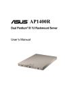
Clarendon & Ashdon
Log Effect Stove Range
Balanced Flue
With upgradeable control valve
Instructions for Use,
Installation and Servicing
For use in GB, IE (Great Britain and Eire)
This appliance has been certified for use in countries other than those stated. To install this appliance in these countries, it is essential to obtain the
translated instructions and in some cases the appliance will require modification. Contact Gazco for further information.
IMPORTANT
Do not attempt to burn rubbish in this fire. This stove must only be operated with the door secured firmly in position.
The outer casing of this stove will become hot whilst in operation, it is therefore recommended that the appliance be
guarded to protect the young and infirm using a suitable guard.
Ensure that fabrics such as curtains are not positioned above or near to the stoves outer casing.
Please read these Instructions carefully and keep them in a safe place.
They will be needed when servicing the fire.
The commissioning sheet found on page 3 of these instructions should be completed by the installer.
PR0847 Issue 2 (February 2007)
CONTENTS
COVERING THE FOLLOWING MODELS
ASHDON - 8546LUC - P8546LUC / 8544LUC - P8544LUC
CLARENDON 8545LUC - P8545LUC / 8547LUC - P8547LUC
PAGE
APPLIANCE COMMISIONING CHECKLIST
3
USER INSTRUCTIONS
4
INSTALLATION INSTRUCTIONS
8
Technical Specifications
8
Site Requirements
9
Installation
13
Commissioning
19
SERVICING INSTRUCTIONS
20
Servicing Requirements
20
Fault Finding
20
How to replace parts
22
Basic spare parts list
25
Service Record
26
2
APPLIANCE COMMISSIONING CHECKLIST
IMPORTANT NOTICE
Explain the operation of the appliance to the end user, hand the completed instructions to them for safe keeping,
as the information will be required when making any guaranteed claims.
FLUE CHECK
PASS
1.
Flue is correct for appliance
2.
Flue flow test N/A
3.
Spillage test N/A
FAIL
GAS CHECK
1.
Gas soundness & let by test
2.
Standing pressure test
mb
3.
Appliance working pressure (on High Setting)
mb
NB All other gas appliances must be operating on full
MTM fires only. Setting Pressure
High-mb
4.
Gas rate
5.
Does ventilation meet appliance requirements N/A
6.
Have controls been upgraded (Upgradeable models only)
Low-mb
m3/h
8455 Standard
YES
NO
8456 Programmable Time & Temperature
YES
NO
DEALER AND INSTALLER INFORMATION
Dealer . . . . . . . . . . . . . . . . . . . . . . . . . . . . . . . . . . . . . . . . . . . . . . . . . . . . . . . . . . . . . . . . . . . . . . .
Installation Company . . . . . . . . . . . . . . . . . . . . . . . . . . . . . . . . . . . . . . . . . . . . . . . . . .
................................................................................
.................................................................................
................................................................................
.................................................................................
Contact No. . . . . . . . . . . . . . . . . . . . . . . . . . . . . . . . . . . . . . . . . . . . . . . . . . . . . . . . . . . . . . . .
Engineer . . . . . . . . . . . . . . . . . . . . . . . . . . . . . . . . . . . . . . . . . . . . . . . . . . . . . . . . . . . . . . . . . . . .
Date of Purchase . . . . . . . . . . . . . . . . . . . . . . . . . . . . . . . . . . . . . . . . . . . . . . . . . . . . . . . .
Contact No.. . . . . . . . . . . . . . . . . . . . . . . . . . . . . . . . . . . . . . . . . . . . . . . . . . . . . . . . . . . . . . . .
Model No. . . . . . . . . . . . . . . . . . . . . . . . . . . . . . . . . . . . . . . . . . . . . . . . . . . . . . . . . . . . . . . . . .
Corgi Reg No.. . . . . . . . . . . . . . . . . . . . . . . . . . . . . . . . . . . . . . . . . . . . . . . . . . . . . . . . . . . . .
Serial No. . . . . . . . . . . . . . . . . . . . . . . . . . . . . . . . . . . . . . . . . . . . . . . . . . . . . . . . . . . . . . . . . . .
Date of Installation . . . . . . . . . . . . . . . . . . . . . . . . . . . . . . . . . . . . . . . . . . . . . . . . . . . . .
Gas Type . . . . . . . . . . . . . . . . . . . . . . . . . . . . . . . . . . . . . . . . . . . . . . . . . . . . . . . . . . . . . . . . . . .
This product is guaranteed for 2 years from the date of installation, as set out in the terms and conditions of sale between Gazco and your
local Gazco dealer. This guarantee will be invalid, to the extent permitted by law, if the above Appliance Commissioning Checklist
is not fully completed by the installer and available for inspection by a Gazco engineer. The guarantee will only be valid during the
second year, to the extent permitted by law, if the annual service recommended in the Instructions for Use has been completed by a
Corgi registered engineer, and a copy of the service visit report is available for inspection by a Gazco engineer.
3
USER INSTRUCTIONS
2.4
2.5
1. GENERAL
1.1
Installation and servicing must be carried out by a
competent person.
1.2 In all correspondence, please quote the appliance type and
serial number which can be found on the data badge
located at the rear of the stove.
1.3 Ensure curtains are not positioned above the stove, and that
there is at least a clearance of 300mm between the sides of
the stove and any curtains.
1.4 If any cracks are observed in the glass panel, do not use
appliance until the glass has been replaced.
1.5 If, for any reason, the flue has to removed from the stove,
the seals must be replaced in the inner telescopic section
and the inner spigot.
1.6 Do not obstruct the flue terminal in any way i.e. by planting
flowers, trees, shrubs etc in the near vicinity, or by leaning
objects up against the terminal guard.
1.7 Do not use a garden sprinkler so as to allow excessive
amounts of water into the flue terminal.
1.8 Do not stand or place objects on the terminal guard as this
will deform.
1.9 This product is guaranteed for 2 years from the date of
installation, as set out in the terms and conditions of sale
between Gazco and your local Gazco dealer. Please consult
with your local Gazco dealer if you have any questions. In
all correspondence always quote the Model No. and Serial
No.
1.10 The manufacturer considers the full outer casing of this stove
to be a working surface. It will become hot whilst in
operation. A suitable guard is recommended to protect
young children, the aged and infirm.
Please ensure the commissioning checklist is completed by
your installer, as this is a requirement of your Guarantee.
2.6
2.7
2.8
2.9
THE YELLOW FLAMES WILL APPEAR WHEN THE FIRE
HAS GAINED SUFFICIENT HEAT - TYPICALLY 10 TO 20
MINUTES.
IF THE APPLIANCE IS EXTINGUISHED OR GOES OUT IN
USE, WAIT 3 MINUTES BEFORE ATTEMPTING TO
RELIGHT THE APPLIANCE.
3. TURNING OFF THE STOVE
3.1
3.2
2. LIGHTING THE STOVE
2.1
4.1
4.2
1
4.3
AR0914
2.3
To turn the stove off, locate the control valve, turn the lefthand control knob until it points to off ( ). The main burner
will go out leaving the pilot burning.
To turn the pilot off, locate the control valve, turn the righthand control knob until it points to off ( ), the pilot will go
out.
4. UPGRADING YOUR STOVE
Locate the control valve on the appliance. There are two
control knobs on the valve, the right hand knob controls the
pilot ignition and the left hand knob controls the main
burner.
If your appliance has already been upgraded to battery
remote control, please refer to the instructions provided with
the upgrade to operate the remote control. The following
instructions will work for either situation.
2.2
Ensure that the right hand control knob is pointing to off ( ).
Press in the right hand control knob and rotate it
anticlockwise until a click is heard (keep pressing in) and the
knob is pointing to pilot ( ). The pilot should now light. If
the pilot has not lit, repeat the procedure until it does.
Keep the control knob pressed in for 10 seconds and then
release it, the pilot should stay alight. If the pilot goes out,
repeat the procedure until does.
If the pilot will not light after repeated attempts, contact the
retailer or installer from whom the appliance was purchased.
Turn the right hand control to point to main burner ( ) .
The appliance can now be controlled using the left hand
control knob.
Turn the left hand control knob to point to low fire ( ) the
main burner will light on low. The burner can now be
controlled between low and high settings. Turn the control
knob anti-clockwise to increase the flame height and
clockwise to decrease the flame height.
Ensure that the left-hand control knob is pointing to off ( )
4
Your stove is fitted with a control valve that can be easily
upgraded to battery powered remote control. This upgrade
can be fitted by anyone capable of simple DIY jobs and
requires no special training. There are two versions of this
control which can be obtained through your local Gazco
stockist.
STANDARD REMOTE CONTROL This remote control can
control the gas appliance after the pilot has been lit. It can
turn the main burner on and regulate it from low through to
high and back again. It can turn the main burner off leaving
the pilot burning. GAZCO PART NUMBER 8455.
THERMOSTATIC AND TIMER REMOTE CONTROL This
remote control can control the gas appliance after the pilot
has been lit. In ‘MANUAL MODE’ it can be used to turn the
main burner on and manually regulate it from low through
to high and back again. It can also be used to turn the main
burner off leaving the pilot burning. In ‘AUTO MODE’ it will
automatically regulate the room temperature. In ‘TIMER
MODE’ it will turn the fire on and off according to a pre-set
programme and automatically regulate the room
temperature during two on periods. GAZCO PART NUMBER
8456.
USER INSTRUCTIONS
2
5. HANDLING & DISPOSAL OF FIRE CERAMICS
5.1
5.2
5.3
5.4
5.5
The fuel effect and side panels in this appliance are made
from Refractory Ceramic Fibre (RCF), a material which is
commonly used for this application.
Protective clothing is not required when handling these
articles, but we recommend you follow normal hygiene rules
of not smoking, eating or drinking in the work area and
always wash your hands before eating or drinking.
To ensure that the release of RCF fibres are kept to a
minimum, during installation and servicing a HEPA filtered
vacuum is recommended to remove any dust accumulated
in and around the appliance before and after working on it.
When servicing the appliance it is recommended that the
replaced items are not broken up, but are sealed within
heavy duty polythene bags and labelled as RCF waste.
RCF waste is classed as stable, non-reactive hazardous waste
and may be disposed of at a licensed landfill site.
Excessive exposure to these materials may cause temporary
irritation to eyes, skin and respiratory tract; wash hands
thoroughly after handling the material.
AR1610
7.2
Place log B on the left hand side of the burner with the
location bar on the underside of the log fully located in the
long slot of the burner. Make sure the log is as far to the left
as possible. See diagram 3.
3
6. CLEANING THE FIRE
6.1
6.2
6.3
6.4
6.5
6.6
6.7
Only clean the stove when it is cold.
Remove the four black nuts retaining the door. Take care
when removing the door as it is heavy.
Remove all of the ceramic logs, being especialy careful
handling the front ash panels.
The logs should not require cleaning. Do not use a vacuum
cleaner or brush to clean the logs, any large pieces of debris
may be removed by hand.
Ensure any debris is removed from the burner ports.
Replace the ceramics and door referring to section 7.
Use a damp cloth to clean the outer casing of the appliance.
AR1611
7.3
4
7. FUEL BED ARRANGEMENTS
7.1
Place log C on the right hand side of the burner with the
location bar on the underside of the log fully located in the
long slot in the burner. Make sure the log is as far right as
possible. See diagram 4.
Remove the cast iron door using the tool provided. Remove
the front coal retainer by lifting vertically.
NOTE: THE CAST IRON DOOR IS HEAVY, TAKE EXTREME
CARE WHEN HANDLING TO AVOID DAMAGING THE
OUTER CASING.
The fuel bed consists of 5 logs and 2 ash panels. The logs
have letters A,B,C,D and E moulded into them for
identification.
Take the rear log A and place it up against the rear of the
fire sitting on the two flat ledges of the burner. The two legs
of the log should sit between the rear burner ports. See
diagram 2. Ensure there is an equal gap between each side
of the log and the side of the firebox.
AR1612
5
USER INSTRUCTIONS
7.4
Place log D across from the rear log A to log B on the lefthand side. There are cut-outs in both logs for location. See
diagram 5.
8
5
AR1616
7.8
Carefully insert the front coal retainer into the front panel of
the firebox. Take care not the scrape/damage the logs. This
coal retainer sits in two brackets. Ensure it is fully inserted,
leaving approximately a 4 mm gap between the firebox
ledge and the bottom of the coal retainer.
AR1613
7.5
There are two ash panels which lay across the front of the
burner skin. Place the panel with the flat edge facing the left
side of the firebox. There are location holes on this log
which fit over the screw holes of the burner skin.
9
6
AR1617
7.9 Ensure that the fibreglass seal on the back of the door is intact,
locate the door on the four studs and slide back to the
firebox. Secure in place using the four dome nuts and tool
supplied. Do not overtigthen the nuts, see diagram 10.
AR1614
7.6
Place the second ash panel to the right of the first, with the
pointed end of the panel fitting into the V shape. This panel
should locate on the screw holes of the burner skin. Ensure
that both logs are horizontal to the burner ports.
10
7
AR1615
7.7
Place log E across from the rear of log A to log C on the right
hand side. Again, there are cut-outs for location. The front of
the log should sit on the front ash panels and should fit tight
to log C. See diagram 8.
AR0540
NEVER OPERATE THE STOVE WHEN THE DOOR IS
REMOVED.
6
USER INSTRUCTIONS
8. THE FLAME FAILURE DEVICE
8.1
This is a safety feature incorporated in all GAZCO fires
which automatically switches off the gas supply if the pilot
light goes out and fails to heat the thermocouple.
9. ‘RUNNING IN’
9.1
The surface coating on your GAZCO fires will "burn off"
during the first 24 hour of use, producing a harmless and
temporary odour. This will disappear after the short period
of use. If the odour persists, ask your installer for advice.
10. SERVICING
10.1 The fire must be serviced every 12 months by a qualified
Gas Engineer. In all correspondence, always quote the
appliance type and serial number, which may be found on
the data badge.
11. INSTALLATION DETAILS
11.1 To assist in any future correspondence, your installer should
have completed the commissioning sheet at the front of this
manual. This records the essential installation details of this
appliance. In all correspondence always quote the Model
No. and Serial No.
7
INSTALLATION INSTRUCTIONS
TECHNICAL SPECIFICATION
COVERING THE FOLLOWING MODELS:
ASHDON - 8546LUC - P8546LUC / 8544LUC - P8544LUC
CLARENDON - 8545LUC - P8545LUC / 8547LUC - P8547LUC
Model
Gas
Gas
Working
Aeration
Injector
Input kW (Gross)
3/h
CAT.
Type
Pressure
8545LUC-8547LUC
8546LUC-8544LUC
I2H
Natural
(G20)
20 mbar
Ø 1 x 14.5
375
P8545LUC-P8547LUC
P8546LUC-P8547LUC
I3P
Propane
(G31)
37 mbar
Ø 2 x 12
165
Rear Exit Flue
Gas Rate
Country
High
Low
0.600
6.4
3.6
GB, IE
0.221
6.15
3.6
GB, IE
m
Wall Thickness:
Min
Max
200mm
550mm
Efficiency Class I
Flue Outlet Size 100 Ø / 152mm
Gas Inlet Connection Size 8mm Ø
RESTRICTOR REQUIREMENT
Vertical & Horizontal Flue Specification
Vertical Flue Height from Top of Appliance
Horizontal Length
Restrictor Size
500mm up to 1490mm
250mm up to 1000mm
No Restrictor
1500mm up to 3000mm
250mm up to 5000mm
75mm Ø
TOP EXIT - VERTICAL ONLY INCLUDING OFFSET
Vertical Flue Height from Top of Appliance
Restrictor Size
3000mm up to 4990mm
52mm Ø
5000mm up to 1000mm
47mm Ø
Packing Checklist
1
Qty Description
1
Stove
1
Flue Blanking plate
1
Coal Retainer
1
Log set (5 logs)*
1
Ash Panel* (2 Sections)
1
Fixing Kit Containing
1 Instruction Manual
1 Wood Screw
AR1618
1 Rawplug
1 Box spanner
*Packed in appliance
A
B
C
D
E
F
ins
mm
ins
mm
ins
mm
ins
mm
ins
mm
ins
mm
353/4
654
253/4
652
173/4
440
201/2
520
61/4
158
3
75
8
INSTALLATION INSTRUCTIONS
SITE REQUIREMENTS
1.1 TIMBER FRAMED BUILDINGS
1. FLUE AND CHIMNEY REQUIREMENTS
1.5
NOTE: This appliance can only be installed in conjunction
with the flue supplied.
The flue must be sited in accordance with BS5440: Part 1
(latest editon). See diagram 1.
Any terminal which is less than 2 metres above any access
(level ground, balcony or above a flat roof to which people
have access), is to be fitted with the guard.
All vertical and horizontal flues must be securely fixed and
fire precautions followed in accordance with local and
national codes of practice.
A restrictor may be required. Refer to Technical
Specifications on previous page.
1.1
1.2
1.3
1.4
1.6
1.7
It will be necessary to provide additional clearance when
the fire passes through a wall containing any combustible
materials so as to prevent a fire hazard.
The hole through which the flue will pass, must have a steel
sleeve which is positioned so that an air gap of at least
25mm is maintained between the outer surface of the flue,
and any part of the sleeve.
For further guidance on the installation of gas appliances in
timber framed buildings, contact your local buildings control
authority.
NOTE: ATTENTION MUST BE GIVEN TO ALLOWING
ADEQUATE CLEARANCE AT THE SIDES AND REAR OF
THE STOVE, TO PROVIDE ACCESS FOR SERVICING.
1
AR0602
9
INSTALLATION INSTRUCTIONS
SITE REQUIREMENTS
1.4 TOP FLUE UP & OUT KIT (8523/8523AN)
1.2 REAR FLUE 8526
Vertical from the top of the appliance then horizontally out.
(See diagram 3.)
Terminal dimensions:
395 x 200 x 200 mm (H x W x D)
The basic kit comprises:
1 x 500mm vertical length
1 x 500mm terminal length (cut to length on site)
1 x 90 degree elbow
1 x wall plate
1 x 75mm restrictor fixing screws
Cut to length as required on site.
2
The kit is the minimum required. Extra lengths may be
added to the vertical and horizontal (see section 1.5), with
reference to Diagram 3.
Extra lengths may be added (see section 1.5), with reference
to diagram 3 and the installation instructions of the
appliance.
3
AR0630
Guard Supplied.
1.3 TOP EXIT
Two types of top exit flue terminal are available, horizontal
and vertical. For a horizontal terminal, decide on the
terminal position and measure the height from the top of the
appliance to the centre of the required hole. For minimum
and maximum flue dimensions see diagram 3.
Access must be either above or at the side of the installation
to allow the flue to be assembled on top of the appliance.
When a horizontal terminal is used, the vertical sections are
assembled first, then the 90-degree elbow and finally the
horizontal section including the terminal. If a masonry
installation is to be built, a suitable lintel must be used to
support the opening.
Only the horizontal terminal section can be reduced in size.
Refer to Balanced Flue Technical Information for details of
flue length.
AR1619
Refer to Table A under 3.2, Installation for identifying when
to use the restrictor.
10
INSTALLATION INSTRUCTIONS
SITE REQUIREMENTS
1.5 TOP FLUE UP & OUT WITH ADDITIONAL
BEND
Extra lengths may be added (see section 1.5), with reference
to diagram 4 and the installation instructions of the
appliance.
Refer to Table A under 3.3, Installation to identify when to
use each restrictor.
Any additional bend may be used on the horizontal section
(either 45° or 90°) but the overall horizontal flue run will be
reduced.
Refer to diagram 4.
1.7 TOP FLUE VERTICAL OFFSET KIT
(8530/8530AN) – ALL APPLIANCES
4
Used with kit 8524 only, (see diagram 5). A minimum rise of
500mm (191/2") is required to the first bend.
5
AR1300
AR1299
1.6 TOP FLUE VERTICAL KIT (8524/8524AN) ALL APPLIANCES
1.8 OPTIONAL EXTRA FLUE LENGTHS &
BENDS
Vertical from the top of the appliance. (See diagram 5). A
minimum vertical rise of 3m (9'10") to a maximum of 10m
(32'10")
The basic kit comprises:
2 x 1m lengths
1 x 1m terminal lengths
1 x 52mm restrictor
1 x 47mm restrictor
11
Nominal
Length
Actual
Length
Stainless
Finish
Anthracite
Finish
200mm
140mm
8527
8527AN
500mm
440mm
8528
8528AN
1000mm
940mm
8529
8529AN
45° Bend
N/A
8507
8507AN
90° Bend
N/A
8508
8508AN
Optional Flue Collar
(Stoves Only)
N/A
8548
INSTALLATION INSTRUCTIONS
SITE REQUIREMENTS
4.4
2. VENTILATION
The appliance requires no additional ventilation.
The above dimensions provide adequate clearance at the
side and rear of the fire so that the controls can be rached
and a spillage test performed where applicable.
7
3. INSTALLATION OF THE GAS SUPPLY
3.1
Before installation, ensure that the local distribution
conditions (identification of the type of gas and pressure)
and the adjustment of the appliance are compatible.
Ensure that the gas supply is capable of delivering the
required amounts of gas, and is in accordance with the rules
in force.
Soft copper tubing and soft soldered joints can be used but
must not be closer that 50mm (2") to the underside of the
firebox.
A means of isolating the gas supply to the appliance must be
provided independent of any appliance control.
All supply gas pipes must be purged of any debris that may
have entered, prior to connection to the appliance.
3.2
3.3
3.4
3.5
*
4. APPLIANCE LOCATION
4.1
This fire must stand on a non-combustible hearth that is at
least 12mm thick and projects 50mm minimum from the
base of the fire in all directions.
* Air-space to non-combustible
AR0531
6
5. TIMBER FRAMED BUILDINGS
5.1
A = 954mm
B = 457mm
C = 12mm
5.2
5.3
AR0604
MINIMUM CLEARANCE
4.2 The fire is not suitable for installation against a combustible
wall. All combustible materials must be removed from
behind the fire.
4.3 Ensure you comply with all minimum cleaance
measurements, whether or not to combustible maerials.
12
It will be necessary to provide additional clearance when the
fire passes through a wall containing any combustible
materials as so to prevent a fire hazard.
The hole through which the flue will pass, must have a steel
sleeve which is positioned so that an air gap of at least
25mm is maintained between the outer surface of the flue,
and any part of the sleeve.
For further guidance on the installation of gas appliances in
timber framed buildings, contact your local buildings control
authority.
NOTE: ATTENTION MUST BE GIVEN TO ALLOWING
ADEQUATE CLEARANCE AT THE SIDES AND REAR OF
THE STOVE, TO PROVIDE ACCESS FOR SERVICING.
INSTALLATION INSTRUCTIONS
INSTALLATION
IMPORTANT: ENSURE THAT THE APPLIANCE IS
CORRECTLY ADJUSTED FOR THE GAS TYPE AND
CATEGORY APPLICABLE IN THE COUNTRY OF USE.
REFER TO DATABADGE AND TECHNICAL
SPECIFICATIONS OF THIS BOOKLET.
FOR DETAILS OF CHANGING BETWEEN GAS TYPES
REFER TO SECTION 10, REPLACING PARTS.
3. INSTALLATION OF THE STOVE
3.1
1. CONTROL UPGRADE
1.1
1.2
1.3
1.4
NOTE: THE CAST IRON DOOR IS HEAVY, TAKE EXTREME
CARE WHEN HANDLING TO AVOID DAMAGING THE
OUTER CASING.
Remove the outer sleeve and associated packaging from the
stove. The ceramic logs are located behind the door.
Remove the cast iron door using the tool provided.
Remove the box and place in a safe location.
REFER TO SITE REQUIREMENTS SECTION FOR ALL FLUE
OPTIONS
The appliance is suitable for top or rear flue exit. If a rear
flue has been purchased proceed to 3.1 below. If a top exit
is required, proceed to 3.2.
This stove is fitted with a control valve that can be easily
upgraded to battery powered remote control. There are two
versions of this control which can be obtained through your
local Gazco stockist.
This upgrade can be fitted before or after installation but if
side clearances are limited then it will be easier to upgrade
the stove before installation. Full instructions are included
with the kit.
STANDARD REMOTE CONTROL This remote control can
control the gas appliance after the pilot has been lit. It can
turn the main burner on and regulate it from low through to
high and back again. It can turn the main burner off leaving
the pilot burning. GAZCO PART NUMBER 8455.
THERMOSTATIC AND TIMER REMOTE CONTROL This
remote control can control the gas appliance after the pilot
has been lit. In "MANUAL MODE" it can be used to turn the
main burner on and manually regulate it from low through
to high and back again. It can also be used to turn the main
burner off leaving the pilot burning. In "AUTO MODE" it will
automatically regulate the room temperature. In "TIMER
MODE" it will turn the fire on and off according to a pre-set
programme and automatically regulate the room
temperature during two on periods. GAZCO PART NUMBER
8456.
.
3.1 REAR EXIT FLUE
WALL THICKNESS
MIN
200mm
MAX
600mm
3.1.3 Remove the adjustable flue assembly and terminal guard
from the box. Take care not to lose the fixings.
3.1.4 Decide on the final stove position and ensure that all
external flue terminal clearances are complied with, See
Section 1, Site Requirements. Mark the centreline of the
appliance on the wall and mark the height from the top of
the hearth to the centre of the flue. See diagram 1.
1
2. SAFETY PRECAUTIONS
2.1
2.2
2.3
2.4
2.5
2.6
This appliance must be installed in accordance with the rules
in force, and used only in a sufficiently ventilated space.
Please read these instructions before installation and use of
this appliance.
These instructions, must be left intact with the user.
Do not attempt to burn rubbish on this appliance.
In your own interest, and those of safety, this appliance must
be installed by a competent person in accordance with local
and national codes of practice. Failure to install the
appliance correctly could lead to prosecution.
Keep all plastic bags away from young children.
Do not place any object on, or near to the stove. Allow
adequate clearance above the stove.
IF THE APPLAINCE IS EXTINGUISHED OR GOES OUT I N
USE, WAIT 3 MINUTES BEFORE ATTEMPTING TO
RELIGHT THE APPLIANCE.
AR0605
TAKE CARE WHEN MARKING OUT FOR THE FLUE. IT IS
DIFFICULT TO MOVE AFTER INSTALLATION.
A 152mm (6") diameter hole is required to install the flue.
This can be achieved by either:
a) Core Drill.
b) Hammer & Chisel.
It is advisable to drill small holes around the circumference
when using method b). Make good at both ends of the hole.
13
INSTALLATION INSTRUCTIONS
INSTALLATION
3
3.1.5 To set the flue length, measure the total wall thickness, then
add 65mm. This total flue length will give the minimum
clearance of 50mm between the rear of the stove and the
wall. To cut the flue to length using a hacksaw, first insert
the square cardboard fitment into the flue. This will support
the inner flue. Cut through the flue and fitment. See diagram
2. ENSURE THE REMAINING FITMENT IS REMOVED
FROM THE FLUE. File the cut edges of the flue smooth.
2
AR0606
Any terminal which is less than 2 meters above any access
(level ground, balcony or above a flat roof to which people
have access), is to be fitted with the guard supplied, see
diagram 4.
AR0630
4
3.1.6 From outside, locate the flue assembly into the hole until the
terminal is flat against the wall. Ensure the terminal is
vertical. NOTE THE ORIENTATION OF THE TERMINAL.
See diagram 3. Mark the four fixing holes, remove the
terminal and drill the holes, inserting the rawplugs supplied.
DO NOT FIX THE FLUE AT THIS STAGE.
3.1.7 Position the stove ensuring all appropriate clearances are
observed.
3.1.8 Before fixing the flue in the wall, apply a bead of suitable
weatherproof sealant (silicone or similar) around the
perimeter of the back face of the terminal B Diagram 3.
Feed the flue through the wall ensuring it travels smoothly.
Working from inside, engage the flue in the inner and outer
spigots, making sure the rubber seals on the spigots are not
damaged.
From the outside, insert the four screws in the flanges of the
flue terminal ensuring the sealant has formed a water tight
joint to the wall. Finally secure the flue to the spigot by
drilling a 3.5mm hole through the larger hole in the spigot
and insert the stainless steel screw provided; refer to C in
Diagram 3.
AR0603
14
INSTALLATION INSTRUCTIONS
INSTALLATION
3.2.3 If the horizontal terminal is used assemble the required
amount of vertical flue including the 90° elbow onto the
stove. Drill through the fixing hole in the spigot using a
3.5mm drill and secure with the screw provided. Do not
forget the optional decorative collar if you have purchased
one. A wall plate is supplied to secure the flue to the inside
wall. Bend the tab to 90° and loosely place on the elbow.
3.2 TOP EXIT
3.2.1 There are two types of top exit flues available, one with a
vertical terminal, the other with a horizontal terminal.
Minimum and maximum flue lengths are shown in Diagram
3 under Site Requirements, 1.4. There is an optional
decorative collar, part No. 8548, to cover the gap between
the top plate and the flue.
THIS MUST BE IN PLACE BEFORE THE FLUE IS
INSTALLED.
IMPORTANT: WHEN INSTALLING A TOP EXIT FLUE
REFER TO THE TECHNICAL SPECIFICATIONS ON THIS
PAGE FOR THE APPROPRIATE SIZE RESTRICTOR.
6
VERTICAL & HORIZONTAL FLUE
TABLE A - TOP EXIT FLUE - VERTICAL AND HORIZONTAL
RESTRICTORS
Vertical Flue Height
From Top of Stove
Horizontal Length
Restrictor Size
500mm to 1490mm 250mm to 1000mm
No restrictor
1500mm to 3000mm 250mm to 5000mm
75mm Ø
3.2.2 The appliance is factory set for rear exit, therefore for top
exit the spigots and blanking plates must be reversed. See
diagram 5. Take care not to drop or damage the gaskets. If a
restrictor is required fit this between the small outlet spigot
and the air duct. See diagram 5. The large outer spigot must
be fitted with the flue fixing hole facing forward.
AR0628
5
3.2.4 To determine the height of the hole for the horizontal flue,
measure from the hearth to the centre of the elbow. See
Diagram 6.
TAKE CARE WHEN MARKING OUT FOR THE FLUE. IT IS
DIFFICULT TO MOVE AFTER INSTALLATION.
A 152mm (6") diameter hole is required to install the flue.
This can be achieved by either:
a) Core Drill
b) Hammer & Chisel
It is advisable to drill small holes around the circumference
when using method b). Make good at both ends of the hole.
3.2.5 The final length of horizontal flue pipe incorporates the
terminal. This is the only section that can be shortened.
DO NOT ATTEMPT TO SHORTEN ANY OTHER SECTION
OF FLUE PIPE.
The fixing holes for the wall plate can only be marked on
the wall. Use the wall plate as a template. The securing tab
can be either on top or underneath the flue. See diagram 7.
AR0627
15
INSTALLATION INSTRUCTIONS
INSTALLATION
3.3 TOP EXIT - VERTICAL FLUE
3.2.6 To determine the length of the terminal flue section measure
from the outside of the wall to the stop on the 90° elbow.
Horizontal flue sections may fitted between the elbow and
the terminal section. See diagram 7.
3.3.1 If a vertical only flue system has been purchased refer to
Site Requirements, Diagram 5.
The following areas need careful consideration:a) Terminal positions
b) Flue supports
c) Weatherproofing
d) Fire precautions
7
For all of the above, local and national codes of practice
must be adhered to.
TABLE A - TOP EXIT – VERTICAL ONLY,
INCLUDING OFFSET
Vertical Height
From Floor
Restrictor Size
3,000mm to 4,990mm
52mm Ø
5,000mm to 10,000mm
47mm Ø
Flue temp
400°C
AR0629
3.2.7 Once the length of the terminal has been obtained, mark
the flue all the way round, insert the cardboard fitment as
shown in diagram 8. This will support the inner flue. When
cutting take care not to damage the edges of the flue. File
any sharp edges from the cut end of the flue.
4. HANDLING & DISPOSAL OF FIRE CERAMICS
The fuel effect and side panels in this appliance are made
from Refractory Ceramic Fibre (RCF), a material which is
commonly used for this application.
Protective clothing is not required when handling these
articles, but we recommend you follow normal hygiene rules
of not smoking, eating or drinking in the work area and
always wash your hands before eating or drinking.
To ensure that the release of RCF fibres are kept to a
minimum, during installation and servicing a HEPA filtered
vacuum is recommended to remove any dust accumulated
in and around the appliance before and after working on it.
When servicing the appliance it is recommended that the
replaced items are not broken up, but are sealed within
heavy duty polythene bags and labelled as RCF waste.
RCF waste is classed as stable, non-reactive hazardous waste
and may be disposed of at a licensed landfill site.
Excessive exposure to these materials may cause temporary
irritation to eyes, skin and respiratory tract; wash hands
thoroughly after handling the material.
8
AR0630a
REMOVE ANY CARDBOARD FITMENT REMAINING.
3.2.8 Remove the stove and flue assembly from the hearth and
drill the four fixing holes for the wall plate, insert the
rawlplugs supplied. Assemble the horizontal flue onto the
elbow and reposition the stove ensuring the flue slides
smoothly through the wall. alternatively, place the flue
terminal in the wall, place the stove on the hearth and
connect the flue to the elbow. Reposition the stove.
3.2.9 Fix the wall plate to the wall using the four black screws
provided. Drill through the fixing tab of the wall plate using
a 3.5mm drill and secure with the screw provided. Make
good and weatherproof around the outside of the flue.
16
INSTALLATION INSTRUCTIONS
INSTALLATION
11
5. FUELBED ARRANGEMENTS
Remove the cast iron door using the tool provided. The
main ceramic components are inside the firebox.
NOTE: THE CAST IRON DOOR IS HEAVY, TAKE EXTREME
CARE WHEN HANDLING TO AVOID DAMAGING THE
OUTER CASING.
The fuel bed consists of 5 logs and 2 ash panels. The logs
have letters A,B,C,D and E moulded into them for
identification.
Take the rear log A and place it up against the rear of the
fire sitting on the two flat ledges of the burner. The two legs
of the log should sit between the rear burner ports. See
diagram 9. Ensure an equal gap between each side of the
log and the side of the firebox.
5.7
AR1612
5.2
9
Place log D across from the rear log A to log B on the lefthand side. There are cut-outs in both logs for location. See
diagram 12.
12
AR1610
AR1613
5.8
Place log B on the left hand side of the burner with the
location bar on the underside of the log fully located in the
long slot of the burner. Make sure the log is as far to the left
as possible. See diagram 10.
5.3
10
There are two ash panels which lay across the front of the
burner skin. Place the panel with the flat edge facing the left
side of the firebox. There are location holes on this log
which fit over the screw holes of the burner skin.
13
AR1611
AR1614
5.1
Place log C on the right hand side of the burner with the
location bar on the underside of the log fully located in the
long slot in the burner. Make sure the log is as far right as
possible. See diagram 11.
17
INSTALLATION INSTRUCTIONS
INSTALLATION
5.4
Place the second ash panel to the right of the first, with the
pointed end of the panel fitting into the V shape. This panel
should locate on the screw holes of the burner skin. Ensure
that both logs are horizontal to the burner ports.
5.7
14
Ensure that the fibreglass seal on the back of the door is
intact, locate the door on the four studs and slide back to
the firebox. Secure in place using the four dome nuts and
tool supplied, do not overtigthen the nuts, see diagram 17.
17
AR1615
5.5
Place log E across from the rear of log A to log C on the right
hand side. Again, there are cut-outs for location. The front of
the log should sit on the front ash panels and should fit tight
to log C. See diagram 15.
15
AR0540
NEVER OPERATE THE STOVE WHEN THE DOOR IS
REMOVED.
6. LIGHTING
6.1
AR1616
5.6
Carefully insert the front coal retainer into the front panel of
the firebox. Take care not the scrape/damage the logs. This
coal retainer sits in two brackets. Ensure it is fully inserted,
leaving approximately a 4 mm gap between the firebox
ledge and the bottom of the coal retainer.
16
AR1617
18
Full instructions are given in the User section under Lighting
the Stove.
INSTALLATION INSTRUCTIONS
COMMISSIONING
1. COMMISSIONING
1.1
Having run the gas supply to the stove, PURGE THE SUPPLY
PIPE, this is essential to expel any debris that may block the
gas controls. Connect the gas supply to the 8mm
compression elbow at the RH rear corner of the stove, see
diagram 1.
Connect a suitable pressure gauge to the test point located
on the inlet fitting, and turn the gas supply on. Light the
appliance and check all gas joints for possible leaks. Turn the
appliance to maximum and check that the supply pressure is
as stated on the data badge. Turn the gas off and replace the
test point screw, turn the gas on and check the test point for
leaks.
1.2
1
AR0934
1.3
Check that the installation instructions and any local
regulations are complied with. Check that all seals are in
good condition. Complete the Appliance Commissioning
Checklist at the front of these Instructions. Explain the
operation of the appliance to the end user.
Hand the completed instructions to the User for safe
keeping, as the information will be required when making
any guarantee claims.
19
SERVICING INSTRUCTIONS
SERVICING / FAULT FINDING CHARTS
1.4
1. SERVICING REQUIREMENTS
1
20
SYSTEM OK
GO TO THE NEXT CHARGE
IGNITION FUNCTIONAL CHECK 2
There is a block in the system. Check the inlet test point and the mag seating.
NO
Has the system got any air in it?
YES
Purge the gas pipes and retry.
YES
Is the gas pressure correct?
NO
Correct and retry.
YES
NO
Is the gas turned on to the appliance?
Check isolation tap and gas meter.
Retry.
NO
YES
Will the pilot light with a match?
YES
Check alignment of pilot burner
head. Change the ignition lead. See
Replacing Parts, Section 2.
NO
Is the control being operated
correctly?
NO
Consult User Instructions and retry.
Operate the valve. Is there a spark?
YES
Does the pilot light?
YES
AR0620
NO
Ensure there is no debris around the pilot assembly, (e.g. soot, etc.) which could short the spark.
Clean the area.
1.3
PILOT WILL NOT LIGHT
1.2
1.5
This appliance must be serviced at least once a year by a
competent person.
All tests must be serviced by best practice as described by
the current CORGI recommendations.
Before any test are undertaken on the appliance, conduct a
gas soundness test for the property to ensure that there are
no gas leaks prior to starting work.
Before any tests are undertaken on the appliance it is also
recommended to fully check the operation of the appliance
Special checks
1.3.1 Clean any lint or fluff from the pilot
1.3.2 Clean away any fluff or lint from under the
burner
1.3.3 Check that the spark gap on the pilot is
correct
1.3.4 Check all of the screws which secure the burner
skins and tighten if they are loose.
IGNITION FUNCTIONAL CHECK 1
1.1
Correct any faults found during the initial tests and then
recommission the appliance conducting the usual safety
checks.
Advise the customer of any remedial action taken.
21
Change the pilot
unit.
NO
YES
Tighten the
connection and
retry.
SYSTEM OK
Will pilot stay alight?
YES
Run for 60 seconds,
turn off, time
interval until mag
NO
unit shuts with a
NO click. Is this greater
Change mag unit.
than 7 seconds?
Replace the
thermocouple.
With the fire
NO Will the pilot stay YES
With the pilot
running on full, is
lit?
running, is the gas
the gas at the
pressure stated on NO Problem is with the NO pressure stated on
the databadge?
pipework or fittings
the databadge?
which lead to the
YES
fire. Correct and
Run for no more
YES
retry.
than 60 seconds,
turn off, time
interval
until mag
Is the pilot flame of
Is thermocouple NO
unit
shuts
with a
the correct length?
connection good in
click. Is this greater
See diagram 1 on
back of valve?
than 7 seconds?
page 19.
YES
NO
YES
Replace the pilot unit.
NO
Replace the combined lead,
retry.
Is the electrode wire detached
from the piezo in the valve?
NO
Remove the electrode lead
from electrode with insulated
YES
pliers. Hold the tip 4mm from
the pilot pipework, is there a
spark when the valve ‘clicks’?
NO
Has ignition lead become
detached or is connection
poor?
YES
Is the pilot burner horizontal?
See diagram 1 on page 20.
YES
YES
YES
NO
Replace the electrode lead
and retry.
YES
Remove the electrode lead
from the piezo. Operate the
valve. Does a spark jump from
the piezo to the valve body?
Check the defective or
damaged control knob spindle
or cam operation. Check for
correct location of piezo
components. Correct and
retry.
Correct and retry.
Reset the electrode gap, retry.
Is the valve being operated
properly?
Operate the valve to light the
pilot, does the valve ‘click’?
NO
Consult the Users Instructions,
retry.
Ensure there is no debris around the pilot assembly, (e.g. coal, soot
etc.) which could short the spark, clear the area.
Ensure there is no debris around the pilot assembly, (e.g. coal, soot
etc.) which could short the spark, clear the area.
From Ignition Fault Finding
Chart Part 1.
NO SPARK
PILOT WILL NOT STAY LIT OR FIRE GOES OUT IN USE
Light the pilot and keep the control knob pushed in at least 10
seconds before letting go.
IGNITION FUNCTIONAL CHECK 2
FLAME FAILURE FUNCTIONAL CHECK 3
YES
SERVICING INSTRUCTIONS
SERVICING / FAULT FINDING CHARTS
SERVICING INSTRUCTIONS
REPLACING PARTS
1. GENERAL
1.1
3. PILOT UNIT
All principal components can be replaced without removing
the stove from its installation, although it is essential that the
gas supply to the appliance is turned off at the isolation
device before proceeding further.
If, for any reason, the flue has to be removed from the stove,
the seals must be replaced.
1.2
The pilot assembly consists of five components, which can
be individually changed, these are:
1) Pilot burner bracket
2) Pilot injector
3) Electrode
4) Thermocouple
5) Gasket.
2. MAIN BURNER
2.1
3.1
Turn the gas supply off at the isolation device, remove the
door and place to one side, carefully remove the ceramic
fuel bed components.
Remove the three securing screws, two at the rear and one
at the front left hand side. See diagram 1. Raise the left hand
side of the burner to clear the bracket, draw the left hand
side forward. The burner venturi is engaged over the
injector. When removing the burner be sure to clear the
injector, this will release the right hand side of the burner.
Take care when removing the burner so as not to damage
the pilot burner.
2.2
Turn the gas supply off at the isolation device, remove the
door and place to one side, carefully remove the ceramic
fuel bed components
Refer to Section 2 to remove the main burner. Remove the
thermocouple baffle taking note of how it is positioned.
Refer to Diagram 2
3.2
2
1
AR1609
3.3
3
AR1605
2.3
Remove the two fixing screws from the pilot bracket, see
diagram 3. Gently draw the assemble away from the firebox
to give access to the nuts and ignition lead.
NOTE: TAKE CARE NOT TO DAMAGE THE GASKET.
To replace the burner, engage the venturi over the injector
ensuring the burner sits on top of the fixing bracket. Push
the burner to the right and whilst holding, insert the three
fixing screws.
NOTE: BEFORE REPLACING THE BURNER, ENSURE THE
SILICONE SEAL AROUND THE INJECTOR IS INTACT AND
CHECK THAT VENTURI COVER IS ATTACHED.
AR0614
22
SERVICING INSTRUCTIONS
REPLACING PARTS
3.4
To remove the pilot injector, undo the compression nut on
the pilot feed pipe and withdraw the injector which will be
hooked onto the olive. When replacing an injector always
make sure it is hooked onto the olive before inserting it into
the pilot burner. See diagram 4.
6
4
AR1617
7
A
AR1604
3.5
To remove the electrode, disconnect the ignition lead and
undo the retaining nut. The electrode can now be removed,
note the orientation of the electrode terminal when
reassembling. See diagram 5.
AR0943
3.7
To remove the gasket, disconnect all the above components
and withdraw the gasket. If it is damaged, replace with a
new item. Always replace the gasket first when reassembling
the pilot components.
5
4. IGNITION LEAD
4.1
Gain access to the back of the pilot assembly, see Section 3
above and disconnect the ignition lead from the electrode.
Undo the single screw that secures the left hand side of the
control cover, see Diagram 8.
4.2
8
AR0616
3.6
To remove the thermocouple, undo the retaining nut and
withdraw the thermocouple, see diagram 6. Undo the
thermocouple from the back of the gas valve, see diagram 7,
arrow A. Reassemble in reverse order. Do not overtighten.
AR0915
23
SERVICING INSTRUCTIONS
REPLACING PARTS
4.3
To release the right hand side of the control cover insert the
narrow blade screwdriver into the slot shown in diagram 9.
Lever it gently and pull from the right hand side at the same
time. The cover will now come off, there is a small
cylindrical metal spacer inside the cover, this must be kept
and replaced on the fixing screw during reassembly.
6.5
6.6
Replace in reverse order.
Check all joints for gas leaks, check the operation of the
thermocouple and ignition lead.
11
B
C
9
C
A
AR0916
4.4
7. MAGNETIC SAFETY VALVE
Disconnect the end of the ignition lead from the valve body,
see diagram 10, Arrow B, note the existing route of the
ignition lead.
7.1
7.2
10
7.3
Turn the gas supply off at the isolation device. Undo the
thermocouple connection from the back of the gas valve.
Undo the mag valve retaining nut at the back of the control
valve, gently tap out the mag valve and replace with a new
unit. Replace the retaining nut and tighten. See diagram 11,
Arrow A.
Secure the thermocouple in the rear of the gas control. (Do
not over tighten). Turn the gas supply on and check the
entire pipework and valve joints for any leaks.
8. MAIN INJECTOR
B
8.1
AR0943
4.5
4.6
8.2
Replace with a new ignition lead following the same route as
the old one. Replace the valve cover and the pilot assembly.
Check the operation of the new ignition lead.
8.3
Turn the gas supply off at the isolation device. Refer to
Section 2, Replacing Parts to remove the main burner.
Undo the compression nut from the feed pipe at the gas
control under the appliance.
Working from inside the firebox, remove the lock nut from
the injector, see diagram 12 and withdraw the injector
complete with the feed pipe from under the appliance.
12
5. PIEZO
5.1
AR0943
The piezo assembly used on this appliance is not serviceable
and is unlikely to fail.
6. GAS VALVE
6.1
6.2
6.3
6.4
Turn the gas supply off at the isolation device.
Disconnect the 2 x 8mm and 1 x 4mm gas pipe fittings at
the back of the gas valve and also disconnect the
thermocouple, see Diagram 11, Arrow A.
Remove the control valve cover and disconnect the ignition
lead from the gas valve, see section 4.
Undo the two bolts securing the gas valve to the appliance
and remove the valve, see diagram 11, Arrow C
AR0918
24
SERVICING INSTRUCTIONS
REPLACING PARTS
8.4
8.5
Holding the injector with a spanner, undo the feed pipe.
NOTE: THE ORIENTATION OF THE INJECTOR.
Reassemble in reverse order, turn on the gas supply and
check for any leaks.
10. CHANGING BETWEEN GAS TYPES
In order to change between gas types, it will be necessary to
change the following items:
- Pilot Injector
- Control Valve
- Main Injector
- Main Burner
- Aeration Plate
- Databadge
The relevant parts can be ordered from the parts list, always
quote the appliance type and serial number when ordering
spare parts.
NOTE: THE CONTROL VALVE IS FACTORY PRESET FOR
THE CORRECT GAS TYPE AND MODEL, A NEW UNIT
WILL NEED TO BE ORDERED WHEN CHANGING
BETWEEN GAS TYPES.
9. PRIMARY AERATION PLATE
9.1
9.2
9.3
Turn the gas supply off at the isolation device.
Refer to section 2 to remove the main burner.
Remove the two screws on the burner skin to detach the
venturi cover from the venturi. Slide the venturi cover off the
venturi as per diagram 13.
13
11. CONTROL UPGRADE
See section 4 in User Instructions.
12. SHORT SPARES LIST
AR1608
9.4
Short spares list Bal flue
Refer to the technical specification and databadge to check
the gas type and its required aeration plate. Change the
aeration plate, if necessary.
Component
14
Main Injector
Aeration plate
Pilot injector
Burner assembly
Thermocouple
Magnetic unit
Electrode
Pilot Gasket
Gas valve
Ignition lead
Complete log set
Log A
Log B
Log C
Log D
Log E
Left ash panel
Right ash panel
Standard upgrade kit
Thermostat/timer kit
AR0619
9.5
Reassemble in reverse order with correct aeration plate(s).
Note: Even if no aeration plate is required, the small screw(s)
must be replaced.
25
NG
G20
20mb
IN0045
N/A
PI0026
GZ5369
LPG
G30
G31
29mb
37mb
IN0030
IN0030
N/A
ME1350
PI0015
GZ5388
PI0011
GC0092
PI0053
PI0052
GC0088K
GC0090
CEO583
CEO584
CEO585
CEO586
CEO587
CEO588
CEO589
CEO590
8455
8456
SERVICE RECORDS
1ST SERVICE
2ND SERVICE
Date of Service:...........................................................................
Date of Service:...........................................................................
Next Service Due:.......................................................................
Next Service Due:.......................................................................
Signed:........................................................................................
Signed:........................................................................................
Dealer's Stamp/CORGI Registration Number
Dealer's Stamp/CORGI Registration Number
3RD SERVICE
4TH SERVICE
Date of Service:...........................................................................
Date of Service:...........................................................................
Next ServiceDue:........................................................................
Next Service Due:.......................................................................
Signed:........................................................................................
Signed:........................................................................................
Dealer's Stamp/CORGI Registration Number
Dealer's Stamp/CORGI Registration Number
5TH SERVICE
6TH SERVICE
Date of Service:...........................................................................
Date ofService:............................................................................
Next Service Due:.......................................................................
Next Service Due:.......................................................................
Signed:........................................................................................
Signed:........................................................................................
Dealer's Stamp/CORGI Registration Number
Dealer's Stamp/CORGI Registration Number
7TH SERVICE
8TH SERVICE
Date of Service:...........................................................................
Date of Service:...........................................................................
Next Service Due:.......................................................................
Next Due:........................................................................
Signed:........................................................................................
Signed:........................................................................................
Dealer's Stamp/CORGI Registration Number
Dealer's Stamp/CORGI Registration Number
9TH SERVICE
10TH SERVICE
Date of Service:...........................................................................
Date of Service:...........................................................................
Next Due:........................................................................
Next Service Due:.......................................................................
Signed:........................................................................................
Signed:........................................................................................
Dealer's Stamp/CORGI Registration Number
Dealer's Stamp/CORGI Registration Number
26
Gazco Limited, Osprey Road, Sowton Industrial Estate, Exeter, Devon, England EX2 7JG
Tel: (01392) 261999 Fax: (01392) 444148 E-mail: [email protected]
A member of the Stovax Group