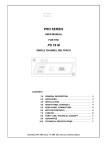
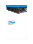
1
Two Channel
Contractor Series Power Amplifiers
SLA150
SLA250
SLA470
MODEL
75W RMS x Two Channels
125W RMS x Two Channels
235W RMS x Two Channels
Distributed Exclusively by:
Stellar Labs™
www.stellarlabs.com
MCM Electronics
www.mcminone.com
Safety Information
The lightning bolt
within a triangle is
intended to alert the
user to the presence
of un insulated
dangerous voltage
levels within the
product’s enclosure.
To reduce the risk of electric
shock, do not remove cover of this
device. There are no user
serviceable parts inside. Refer
servicing only to qualified service
personnel.
This voltage may be of
sufficient magnitude to
constitute an electric
shock risk.
Safety Precautions
•
•
•
•
•
•
•
•
•
•
•
•
•
2
The exclamation point
within a triangle is
intended to alert the
user to important
operating and
maintenance
(servicing)
instructions in the
literature
accompanying the
appliance.
Read and retain these instructions
Follow all instructions and heed warnings
Do not use this device near water
If the surface becomes dirty, clean only with dry cloth, do not use solvents or
thinners
Install in accordance with the manufacturer’s instructions
Do not block ventilation openings
Do not install near heat sources such as radiators, heat registers, stoves, or
other devices that produce heat
Do not defeat the safety purpose of the grounded plug. This plug has two
blades and a third ground prong. The wide blade or third prong are provided
for your safety. If the provided plug does not fit into your outlet, consult an
electrician for replacement of the obsolete outlet
Protect the power cord from being stressed at the plugs, convenience
receptacles, and where they exit the amplifier
Only use accessories specified by the manufacturer
Unplug the device during lightning storms or when unused for an extended
time
Refer all servicing to qualified personnel
This device must not be exposed to water in any way. No object filled with
liquids should be placed on apparatus
Congratulations on your purchase of this
Stellar Labs SLA Series Stereo Amplifier
This amplifier was designed specifically for use in distributed audio installations, where high
reliability and premium sound quality are a must. Remote on/off triggering and signal sensing allow
these units to be set up in equipment racks, with no further contact required. Rear mounted master
level controls keep installation safe from future tampering. Two auto–switching inputs allow
automatic operation when used with more than one system.
This amplifier is warranted from defects for one year from the date of purchase. Should your
amplifier require service, either within or beyond that warranty period, please contact your MCM
Sales Representative.
This unit includes a host of features, along with an impressive list of specifications, which are
detailed over the next pages. Please take the time to read this document completely prior to
installation of this product. Should you have questions regarding installation or operation of this
unit, please contact the MCM Technical Support Department.
Features
Two sets of L/R inputs, each may be switched to accept line level speaker level signal Auto–
switching between inputs, with adjustable delay
Line level pass through output on input #2
Manual or auto–sensing power control
12V trigger input allows power–on command from external components
12V trigger output allows amplifier to trigger external components
Stereo and bridged mono operation
Heavy–duty binding post speaker outputs
Discrete output components
Specifications (all models)
THD: <0.2% (at 4ohm)
Crosstalk: <65dB @ 1KHz
Frequency Response: 20Hz ~ 20KHz +/- 0.5dB
S/N Ratio: >100dB
Model SLA150
50W RMS per channel, both channels driven into an 8ohm load
80W RMS per channel, both channels driven into a 4ohm load
150W RMS bridged mono, into an 8ohm load
Power requirements: Selectable 115/230VAC, 60/50Hz, 450W max
Dimensions: 3 1/2" (H) x 16 1/2" (W) x 14" (D)
Weight: 21 lbs
Model SLA250
80W RMS per channel, both channels driven into an 8ohm load
125W RMS per channel, both channels driven into a 4ohm load
250W RMS bridged mono, into an 8ohm load
Power requirements: Selectable 115/230VAC, 60/50Hz, 700W max
Dimensions: 3 1/2" (H) x 16 1/2" (W) x 14" (D)
Weight: 26 lbs
Model SLA470
150W RMS per channel, both channels driven into an 8ohm load
235W RMS per channel, both channels driven into a 4ohm load
470W RMS bridged mono, into an 8ohm load
Power requirements: Selectable 115/230VAC, 60/50Hz, 1200W max
Dimensions: 5 1/4" (H) x 16 1/2" (W) x 14" (D)
Weight: 33 lbs
3
Front Panel Controls
Power
Provides manual on/off control of the amplifier. For this control to operate normally, the rear
Trigger/Auto-On/Normal selector must be in the Normal position. If using the Trigger or Auto
On mode, this switch must remain in the ON position.
On/Standby Indicator
Bi-color lamp provides immediate indication of the amplifier status. With the power switch OFF, the
lamp is not lit. With the power switch ON, and Trigger or Auto-On in STANDBY mode, the lamp is
red. When the amplifier is manually, automatically (signal sensing) or externally triggered ON, the
lamp lights blue. This allows the user to immediately know the exact status of the amplifier from
anywhere in the room.
A/B Speaker Selector
Each A and B pushbutton operates independently. Pressing the button in will engage the speaker
pair for the designated output. Pressing again will disengage that output. With both pairs on, the
speaker outputs are parallel.
Balance
This provides trim adjustment between the Left and Right audio channels of the amplifier. Note that
this is a “trim” control, in that it provides for fine adjustment between the two channels. Unlike
conventional “balance” controls on consumer audio equipment, this control will not completely mute
the opposing channel, even when turned fully clockwise or counterclockwise.
Volume
This provides volume trim adjustment, simultaneously for the and right channels. Note that the
master volume level is set via the recessed Master Level Controls on the rear panel. The front
panel volume control is intended to provide fine up/down adjustment from the preset level.
This is especially useful in distributed audio applications, as it allows the Installer to set the overall
amplifier limit, while allowing the user only a limited range of adjustment. This greatly reduces the
risk of speaker and component damage from abuse or tampering after the installation is complete.
Caution
Prior to connecting this unit to AC power,
Note the following critical information
Power Source Selection
Locate this switch on the right side of the rear
panel, directly next to the power cord
connection.
Make sure this switch is in the proper connection
prior to connecting power.
Failure to do so could result in permanent
damage to the amplifier and potentially create a
hazard, even if the amplifier is switched off.
4
Rear Panel Connections / Controls
1
2
3
4
5
6
7
L/R Line Input #1
L/R Line Input #2
L/R Input #2 Feed-through
L/R Speaker Level Input
Speaker Input Selector
L/R Master Level Control
Stereo / Bridged Selector
#1)
L/R Line Input #1 (priority)
#2)
L/R Line Input #2 (default)
8
9
10
11
12
13
14
12VDC Trigger Input
12VDC Trigger Output
Power On/Off Mode Select
Speaker Pair “A” Output
Speaker Pair “B” Output
IEC Power Line Cord Input
115/230VAC Power Selector
Conventional line level input accepts signal from typical audio sources, such as tape or CD players,
computer sound cards, MP3 and similar portable devices, television audio outputs or DVD players. If
this amplifier is to be connected to an existing home theater system, to drive remote speakers, this
input should be connected to the home theater’s TAPE, or PREAMP output.
The amplifier automatically defaults to this input upon power up, and will only be active when no
signal is present at the Line #1 Input. As soon as a signal is detected at the Line #1 input, the
amplifier will automatically switch to the Line #1 Input. If silence is detected at the Line #1
Input, it will switch back to the Line #2 Input. If a signal is present at both inputs, the Line #1
Input will take precedence over the Line #2 Input.
The Delay Control will effect length of silence time required to pass prior to switching back to
Input #2. This prevents unwanted switching during quiet passages between songs or in movie
soundtracks.
Ideal application of these two inputs is as follows:
Use the SLA Amplifier to power several zones of speakers throughout the house. Connect the Tape
output from the Home Theater system to the Line #2 Input. When the Theater System is powered
on, the SLA Amplifier will also power on, sending the sound source throughout the home. A
secondary source, such as a remote MP3 player connector, iPod™ docking station or similar, could
be connected to the Line #1 Input. When the portable device is connected to this input, and
powered on, the amplifier will switch to this input, and play throughout the home.
5
#3)
L/R Input #2 Feed-through Output
This output is provided as a convenience feed-through from the Line #2 Input. What ever source
is connected to the Line #2 Input, will play through this line level output. This is ideal for daisy
chaining multiple amplifiers to drive a large number of zones. This output is unaffected by the autoswitching of the SLA Amplifier, as it will always feed from the Line #2 Input.
#4)
Speaker Level Input
This input is intended to accept a signal directly from the speaker output of another audio amplifier.
This can be useful if the audio source feeding the SLA Amplifier has no line level output, such as a
television, or older stereo system.
This input is also useful if an existing whole house audio system is in place, and it is desired to
connect additional zones away from the central system. Or, if a room is added to an existing
system, that requires connection of a large, high powered pair of speakers, or a passive subwoofer.
This Speaker Level Input can be directed to either Input #1 (priority) or Input #2 (default) by use
of the selector switch directly above the input.
#5)
Speaker Input Selector
#6)
Master Amplifier Level Control
Directs the Speaker Level Input to either #1 or #2. When in the #2 position, the speaker level
input will be provided at line level at the #2 Feed-Through Output.
These independent Left/Right controls act as the main volume control for this amplifier. These are
located on the rear to allow the installation contractor to limit the maximum volume level of the
system. The front panel volume control acts as a trim adjustment, relative to the position of these
rear controls.
#7)
Stereo / Bridged–Mono Mode Selector
This selector allows the amplifier to act as a stereo (two channel) amplifier, or a single channel
mono amplifier, with the power of both channels added together. This is useful when using the
amplifier to drive a passive subwoofer.
When using the amplifier in bridged mode, be certain to:
•
Use speaker loads of 8ohm or higher. Speakers or combinations of speakers that yield less
than 8ohms can damage the amplifier
•
Only connect to the “A” speaker output
•
Be certain to observe proper connections
•
Your signal source should be connected to both Left and Right input channels
•
Master level controls should be set at exactly the same level
•
Front panel balance control should be set at the mid position
#8)
12V Trigger Input
#9)
12V Trigger Output
When the Power On/Off Mode Selector is in the Trigger position, the amplifier can be externally
switched ON and OFF from this input. When supplied with 12VDC, the amplifier immediately
switches on. When 12VDC is removed, the amplifier immediately switches off. This input is a twoconductor 3.5mm connector, positive tip polarity. It should be provided with a 12VDC signal only.
This output provides 12VDC, 100mA to control external devices from the ON/OFF operation of this
amplifier. When the amplifier is on, 12VDC is immediately present, and switches off immediately
when the amplifier switches off. This follows whether the Auto-On, 12V Trigger Input or manual
ON/OFF control are used to turn the amplifier on. This allows the amplifiers Auto-Power-On function
to control external devices. This output is a two-conductor 3.5mm connector, positive tip polarity.
Caution: Do not connect loads greater than 100mA to this output.
6
#10) Power On/Off Mode Select
This selector determines how the amplifier will be switched on and off.
Normal provides completely manual operation from the front panel Power switch.
Auto-On senses the presence of an input signal at Input #1 or Input #2. Upon the detection of this
signal, the amplifier turns on immediately. After approximately 10 minutes of no signal, the
amplifier will switch off. This mode requires the front panel POWER button to remain in the ON
position.
Trigger allows external ON/OFF control of the amplifier, through the 12V Trigger Input, found
immediately to the left of this selector. This input looks for a 12VDC signal from an external device
to turn this amplifier on and off. This mode requires the front panel POWER button to remain in the
ON position.
#11) Speaker “A” Output
This binding post set provides connections for speakers controlled by the “A” pushbutton on the
front panel Speaker Selector. These binding posts accept banana plugs, spade lugs, or bare speaker
wire up to 12AWG. Use extreme care when connecting bare speaker wire to ensure that small
strands to not short between adjacent terminals. Left and right speakers should be connected as
normal for stereo operation. For bridged mono operation, the two (RED) positive terminals only are
used. See the notation on the back panel for proper connection.
#12) Speaker “B” Output
This binding post set provides connections for speakers controlled by the “B” pushbutton on the
front panel Speaker Selector. These binding posts accept banana plugs, spade lugs, or bare speaker
wire up to 12AWG. Use extreme care when connecting bare speaker wire to ensure that small
strands to not short between adjacent terminals. Left and right speakers should be connected as
normal for stereo operation. The “B” output is not to be used for bridged operation.
#13) Line Cord Input / Fuse Holder
This provides a standard IEC type AC power cord connection. This removable type cord is
convenient in certain installation applications, as it allow the power cord to be routed into racks or
cabinets at an early stage, with connection of the amplifier later. A 72” cord is included with each
unit, exact replacements are available at MCM Electronics or a variety of electronic/electrical
retailers.
Fuse Holder
Amplifiers are shipped with preinstalled fuses that are the appropriate size for 115VAC operation. If
the amplifier is to be operated at 230VAC, the fuse should be replaced with the proper size. Fuses
are In the event that that fuse blows, only replace with a fuse of the same type and amperage
rating. MCM Electronics recommends Littelfuse 213 Series, miniature 5mm x 20mm Slo–Blo®
replacement fuses.
115VAC
230VAC
Operation
Model #
Operation
SLA150
4A
2A
SLA250
6.3A
3.15A
SLA470
10A
5A
#14) Voltage Input Selector
This selector allows use of the amplifier virtually any place in the world. The default setting for use
in North America is 115V (switch in the up position). However it is recommended to verify this prior
to connecting power. Note that improper power selection can cause immediate and permanent
damage to the amplifier, even if the main power switch is not turned on.
7